1
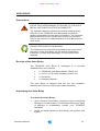
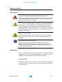
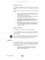
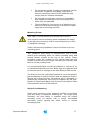
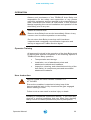
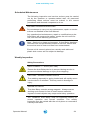
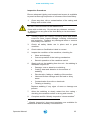
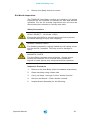
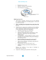
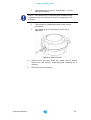
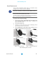
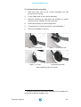
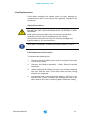
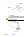
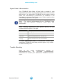
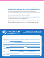
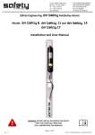
Model TB150-12C
OPERATOR
MANUAL
i
NOTE TO INSTALLERS
Always Read Instructions Before Use
LEAVE THIS OPERATOR MANUAL ATTACHED TO THE AUTO BELAY. THE
OPERATOR MANUAL CONTAINS INFORMATION RELATING TO THE SAFE USE
OF THE TRUBLUE AUTO BELAY AND INCLUDES ALL PRODUCT
REGISTRATION AND WARRANTY INFORMATION. THIS DOCUMENT
MAY ONLY BE REMOVED BY THE END USER. ENSURE USER MANUAL IS
READILY AVAILABLE TO OPERATORS AT ALL TIMES
CE0194
EN 341:1992 + A1:1997 Class A
7001-001-04
TruBlue Auto Belay Operator Manual
www.autobelay.com
Contents
Warranty Conditions ........................................................................ 4
Customer Responsibility
5
Certification ..................................................................................... 6
Standards
6
Description ...................................................................................... 7
Specifications
7
Auto Belay Parts
8
SAFETY INFORMATION ................................................................... 9
Symbols Used in this Manual
9
Read Before Installation and Operation
10
Health and Safety
10
Site Rescue Plan
10
Location of Safety Labels
11
Unpacking ...................................................................................... 12
Precautions
12
Receipt of the Auto Belay
12
Unpacking the Auto Belay
12
Installation .................................................................................... 14
Precautions
14
Standards
14
Mounting
16
Operation.......................................................................................20
Operator Training
20
User Instruction
20
Climbing Harness
21
Operator Manual
1
www.autobelay.com
Carabiner Use
21
Inspection and Maintenance ........................................................ 23
Annual Recertification
23
Scheduled Maintenance
24
Weekly Inspection
24
Six Month Inspection
26
Nozzle Replacement
29
Line Replacement
31
Spare Parts & Accessories
34
Trouble Shooting
34
Transportation
35
Manufacturers Details................................................................... 36
Address:
36
Contact Details:
36
Operator Manual
2
www.autobelay.com
IMPORTANT SAFETY NOTICE
CLIMBING IS A DANGEROUS ACTIVITY
Failure by the operator to heed any and all instructions,
warnings and cautions for the correct installation,
operation, care and maintenance of the TRUBLUE Auto
Belay may result in serious injury and/or death.
TruBlue Auto Belay Model TB150-12C and associated
equipment is designed and specified for use in the
recreational climbing industry as a controlled descent
device. Use of the TruBlue Auto Belay for any purposes
other than that intended by the manufacturer is not
permitted.
Owners and operators of the TRUBLUE Auto Belay are
responsible for the safety and supervision of any person
using the TRUBLUE Auto Belay and are required to undergo
training in the correct installation and operation of the Auto
Belay prior to any use.
These instructions must be made readily available to the
operator at all times. Prior to installation and use, all owners
and operators must have read and shown to have
understood all instructions, labels, markings, and safety
information pertaining to the installation, operation, care,
and maintenance of the TRUBLUE Auto Belay system, its
component parts, and all associated hardware. Failure to do
so can result in death, serious injury and equipment
damage.
Operator Manual
3
www.autobelay.com
WARRANTY CONDITIONS
This TRUBLUE Auto Belay Device is warranted against
factory defects in materials and workmanship (excluding
“Specific Field Replaceable Wear Parts” – see below) for a
period of two (2) years from date of purchase. This warranty
applies only to the original purchaser, and is contingent upon
the owner/operator maintaining and using the device in
accordance with TRUBLUE Auto Belays (TRUBLUE)
instructions, including the requirement to continue to maintain
annual re-certification as described in the Operator’s
Instruction Manual. This Warranty is in lieu of all other
warranties, express or implied.
The sole remedy for breach of this warranty, or for any claim
in negligence or strict liability in tort, is the repair or
replacement of any defective parts by TRUBLUE. Upon
notice in writing, TRUBLUE will promptly repair or replace all
defective items. TRUBLUE reserves the right to have any
defective equipment returned to its plant, transportation prepaid, for inspection before making a repair or replacement.
This Warranty is null and void if parts other than genuine
parts are used, or if any modifications or services have been
performed on the device by anyone other than an authorized
TRUBLUE servicing agent. This warranty does not cover any
damages resulting from abuse to the device, damage in
transit, or any other damage beyond the control of
TRUBLUE. TRUBLUE makes no warranties in respect to
trade accessories or component parts which are not made by
TRUBLUE. TRUBLUE expressly excludes from this Warranty
the replacement of “Specific Field Replaceable Wear Parts”,
which include the nozzle, the webbing (line) kit, carabiner
and/or any anchors supplied with the product.
No person, agent or Distributor is authorized to give any
warranty, other than the one herein expressed, on behalf of
TRUBLUE, or to assume for it any liability pertaining to such
products. TRUBLUE expressly disclaims any implied
guarantee of merchantability, or claim as to whether the
device is suited for a particular purpose. Purchaser agrees
that TRUBLUE shall not be held liable to Purchaser/Operator
for damages of any kind, including but not limited to, lost or
projected profits, equipment down time, or any losses
considered to be caused by non-operation or servicing/recertification down time of the equipment.
Operator Manual
4
www.autobelay.com
Customer Responsibility
The following items are considered to be the responsibility of
the Customer and are therefore are non-reimbursable under
the terms of the warranty.
•
Routine maintenance and inspection.
•
Normal replacement of service items.
•
Replacements required because of abuse, misuse
or improper operational habits of the operator.
•
Wearing parts such as nozzle, webbing line and
carabiner.
•
Normal deterioration due to use and exposure.
This warranty is subject to the following of the requirements
of the Operator Manual supplied, Manufacturer’s instructions,
and the advice given by TRUBLUE service technicians.
Operator Manual
5
www.autobelay.com
CERTIFICATION
Standards
CAUTION
If the Auto Belay is resold outside of the country of
destination, the reseller must provide instructions for use,
service, maintenance and repair in the language of the
country of use.
The TRUBLUE Model TB150-12C can be used as a climbing
system device only in combination with other components. It
shall not be deemed suitable for use until it is ensured that
the entire system complies with the requirements of
appropriate regional, state, and federal directives/standards.
TRUBLUE Auto Belay complies with the following prevailing
Safety regulations
•
AS/NZS 1891: Industrial fall-arrest systems and
devices – Part 3: Fall arrest devices
•
CSA Z259.2.3-99: Descent Control Devices
•
EN 341: 1992 + A1:1997 Class A: Personal
protection equipment against falls from a height –
Descender devices
•
ANSI/ASSE Z359.4: Safety Requirements for
Assisted-Rescue and Self-Rescue Systems,
Subsystems and Components.
Notified body for CE type examination
INSPEC International Ltd
56 Leslie Hough Way
Salford
Greater Manchester, M6 6AJ
United Kingdom
Identification No. 0194
Body controlling the manufacture:
INSPEC International Ltd
56 Leslie Hough Way
Salford
Greater Manchester, M6 6AJ
United Kingdom
Identification No. 0194
Operator Manual
6
www.autobelay.com
DESCRIPTION
The TRUBLUE Auto Belay is a controlled descent device
designed specifically for use in the climbing industry. The
TRUBLUE offers a maximum descent height of 12.5 m (41 ft)
and is suitable for climber weights ranging from 10 - 150 kg
(22 - 330 lbs).
The design of the TRUBLUE permits simple installation and
removal and incorporates an advanced self-regulating brake
system and automatic line retraction. The patented braking
mechanism offers climbers a smooth descent with a minimal
variation in descent rate of both children and adults. There
are no wearing parts in the brake mechanism, ensuring
reliability remains high while maintenance and operating
costs are kept to a minimum.
To protect the longevity of the TRUBLUE, installation, care
and use of the TRUBLUE Auto Belay must be carried out in
accordance with the instructions in this manual.
Specifications
Model:
TB150-12C
Classification:
Class A Descent Control Device
Dimensions:
80 x 320 x 216 mm (15 x 12.6 x 8.5 in)
Net Weight:
19.75 kg (44 lbs)
Materials:
Casing
Aluminium Alloy
Internal parts
Zinc plated steel
Nozzle
Modified Acetal plastic
Line
20 mm Nylon Spectra
webbing
Max. Line Extension:
12.5 m* (41 ft)
* Other line lengths are available from the manufacturer
Operator Manual
Min. Climber Weight:
10 kg (22 lbs)
Max. Climber Weight:
150 kg (330 lbs)
Max. Descent Speed:
2.0 m/s (6.5 ft/s)
7
www.autobelay.com
Auto Belay Parts
Certification Labels
Operator Manual
8
www.autobelay.com
SAFETY INFORMATION
Symbols Used in this Manual
The following safety symbols are used throughout this
manual to highlight potential dangers. One or more
precautions may be associated with practices and
procedures described within this manual. Failure to adhere to
any precautions highlighted can result in death, serious injury
and equipment damage.
Ensure that you read and understand all safety related
procedures related to the working environment and the task
you are undertaking.
DANGER
Indicates a hazardous situation exists that, if not avoided,
will result in death or serious injury.
WARNING
Indicates a potentially hazardous situation that, if not
avoided, could result in death or serious injury.
CAUTION
Indicates a potentially hazardous situation that, if not
avoided, may result in injury or equipment damage.
NOTE
Indicates an action that must be taken to ensure personal
safety and prevent damage to property or equipment.
CARE FOR THE ENVIRONMENT
Take care to minimize impact on the environment when
carrying out this procedure.
Operator Manual
9
www.autobelay.com
Read Before Installation and Operation
WARNING
Failure by the operator to heed all instructions, warnings
and cautions for installation and use of the TRUBLUE Auto
Belay can result in serious injury and/or death.
Owners and operators of the TRUBLUE Auto Belay are
responsible for the safety and supervision of any person
using this equipment. Owners and Operators are required by
the Manufacturer to read, understand, and follow all
instructions in this Operators Manual regarding the correct
installation and operation of the Auto Belay prior to any use.
These instructions must be made readily available to the
operators and users at all times. Prior to installation and use
all owners and operators must have read and shown to have
understood all instructions, labels, markings, and safety
information pertaining to the installation, operation, care, and
maintenance of the TRUBLUE Auto Belay system, its
component parts and all associated hardware.
Health and Safety
Owners and operators must abide by all Standards,
International, Federal, State and Provincial laws, and any
specific health and safety regulations pertaining to the
installation and use of this product.
Site Rescue Plan
Owners and operators must have devised an emergency
rescue plan for any climber in distress at all sites operating
TRUBLUE Auto Belay devices. Operators must inform Users
of the Auto Belay of the procedure for rescuing a climber in
distress prior to climbing.
Operator Manual
10
www.autobelay.com
Location of Safety Labels
Operator Manual
11
www.autobelay.com
UNPACKING
Precautions
LEAVE THIS USER MANUAL ATTACHED TO THE AUTO
BELAY UNTIL INSTALLATION IS COMPLETE
The Operator Manual contains information relating to the
safe use of the TRUBLUE Auto Belay and includes all
product registration and warranty information. The Operator
Manual document may only be removed by the end user.
Ensure this manual is readily available to Auto Belay users
at all times.
DO NOT DISPOSE OF PACKAGING
The cardboard box and internal packaging are required for
the return of the Auto Belay for the annual Certification
inspection. Please keep packaging in a safe place until
required.
Receipt of the Auto Belay
The TRUBLUE Auto Belay is packaged in a recycled
cardboard box and contains:
•
1 x TRUBLUE Auto Belay Model TB150-12C
•
1 x 12.5 m (41 ft) Nylon Webbing Lower Line
•
1 x Carabiner
•
1 x Operator Manual
The Auto Belay is shipped with the line and carabiner
attached and does not require any further assembly.
Unpacking the Auto Belay
To unpack the Auto Belay:
Operator Manual
1.
Upon receipt of Auto Belay, inspect for signs of shipping
damage or contamination. If Auto Belay shows any signs
of damage or mishandling contact your TRUBLUE
distributor.
2.
Check all labels affixed to Auto Belay are present and
legible.
12
www.autobelay.com
Do not use the Auto Belay after date shown here
3.
Check the Certification Label for the ‘Next Recertification
Required’ date. If the date shown has passed or the
label is missing or illegible the Auto Belay must not be
put into service.
4.
Fill out Product Registration Card included with Auto
Belay and return it to your TRUBLUE distributor or
register online at www.autobelay.com/registration
PRODUCT REGISTRATION MUST BE COMPLETED
The Product Registration must be completed, either by filling
out and returning the Product Registration Card or by
registering online. This is critical for receiving product
notifications and up-to-date information for the safe use of the
TRUBLUE Auto Belay.
5.
Read the Operator Manual and familiarize yourself with
all aspects of installation, operation, care and
maintenance.
Storage
If the Auto Belay is to be left unused for longer than two
weeks, ensure the unit is clean and dry and line is fully
retracted into the unit.
When returning the Auto Belay to duty after and an extended
period of inactivity always carry out a full inspection and
operational check.
DO NOT STORE IN A WET CONDITION
After exposure to water or damp conditions thoroughly clean
and dry the Auto Belay. Ensure Auto Belay is not left with wet
webbing line retracted inside the casing.
Always store in a clean and dry environment.
Operator Manual
13
www.autobelay.com
INSTALLATION
Precautions
ALWAYS USE DESIGNATED MOUNTING POINTS
Never install the Auto Belay using any part of the device apart
from the designated mounting points. Incorrect mounting can
result in serious injury or death.
HARD IMPACTS MAY RESULT IN STRUCTURAL DAMAGE
Dropping of, or hard impacts to, the Auto Belay can result in
serious damage to mounting points and internal parts and
may compromise safety of operation – If Auto Belay is subject
to a hard impact, remove it from duty and return to the service
agent for inspection.
HEAVY ITEM - 20 KG
Take care when lifting the Auto Belay. Take care not to drop
the device as this may result in serious injury or equipment
damage.
ALWAYS MOUNT VERTICALLY
Always mount the Auto Belay vertically with the nozzle
pointing downwards and the line exiting the bottom of the
device. Failure to do so will result in incorrect operation and
compromise User safety.
Standards
Prior to installation, all Operators must be familiar with the
requirements of all relevant Standards for anchor points,
hardware and equipment used with the Auto Belay.
Anchor Points
All anchor points and connectors used with the TRUBLUE
Auto Belay must conform to any federal, state requirements
for such devices
.
Operator Manual
14
www.autobelay.com
Minimum requirements for anchor points must conform to the
requirements of:
•
EN 12572 - Climbing wall anchor points.
•
EN 795 - Anchor Devices.
The location and anchor points for the TRUBLUE Auto Belay
should comply with the following:
•
Minimum load capacity of the anchor point(s) 20 kN
(4400 lbs) in expected directions of application.
•
Anchor points are not to be used by other devices
or as attachments for hardware not associated with
the Auto Belay installation.
•
Anchor points should be of a suitable size to
correctly install any mounting hardware.
Harness
All harnesses used in conjunction with the TRUBLUE Auto
Belay must comply with following standards:
•
EN 361 - Personal protective equipment for
prevention of falls from a height – Full body harness
•
EN 813 - Personal protective equipment for
prevention of falls from a height – Sit harness.
•
EN 12277 - Type A. Full Body Harness
•
EN 12277 - Type B. Small Full Body Harness
•
EN 12277 - Type C Sit Harness
Harnesses must be of the correct size and fitment and be in
serviceable condition.
Secondary Connectors
All secondary connectors and hardware used in the
installation of the TRUBLUE Auto Belay must conform to the
requirements of:
•
EN 362 - Types of connectors for personal
protection.
•
EN 12275 - Types of connectors for
mountaineering.
All connectors, hooks, D-rings and shackles used to mount
the TRUBLUE Auto Belay must meet a minimum breaking
load of 20kN (4400 lbs) and be of compatible size, shape and
strength for the mounting point to which they are attached.
Operator Manual
15
www.autobelay.com
Selecting a Location
The TRUBLUE Auto Belay is to be mounted at the top of the
climbing route with the nozzle and webbing line pointed
down.
When selecting a location to mount the Auto Belay always
check:
•
All anchor points have a minimum load capacity of
20kN (4400 lbs) and conform to all federal and state
requirements for such devices.
•
The Auto Belay will hang vertically over the climbing
route with the nozzle pointing down.
•
All paths that can be used by the climber when
connected to the Auto Belay are free of sharp edges
and high friction surfaces that may damage the
webbing line.
•
Ensure that the descent path and landing area are
free of other climbers, pedestrians or obstacles that
may cause entanglement or restrict the climber’s
ascent or descent.
Outdoor Installations
The TRUBLUE Auto Belay may be installed outdoors.
It is recommended that in wet or aggressive environments
the Auto Belay is protected from the direct ingress of water or
foreign objects.
Note - Prolonged exposure to the elements will increase the
risk of internal corrosion and degradation of the webbing line
resulting in increased operation and servicing costs.
Mounting
With a suitable location for the Auto Belay selected it can be
mounted only using the methods and hardware described in
this manual. When mounting the Auto Belay be aware of the
following precautions:
•
Operator Manual
Anchor point must be capable of withstanding a
minimum load of 20 kN (4400 lbs) in expected
direction of load application.
16
www.autobelay.com
•
All connectors, hooks, D-rings and shackles used to
mount the TRUBLUE Auto Belay must meet a
minimum breaking load of 20 kN (4400 lbs) and
comply with the relevant standards.
•
All secondary connectors must be of compatible
size, shape and strength to the mounting point to
which they are attached.
•
The Auto Belay is free to pivot in all directions and
should not bind the mountings or be able to impact
upon the surrounding structure.
Mounting Points
USE ONLY THE DESIGNATED MOUNTING POINTS
Use only the correct mounting points designated for single
or double point mounting. Use of incorrect points can result
in equipment damage.
Ensure all mounting hardware is secure but free to pivot in
mounting point.
The TRUBLUE Auto Belay is manufactured with a single
central pivot mounting point, an offset mounting point and
formed handle located at the top of the casing. These
mounting points are located on the central plate and are
located to ensure the unit hangs centrally and vertically with
the line nozzle pointing down.
It is recommended that a minimum distance of 100 mm (4 in)
is maintained between the Auto Belay and any adjacent wall
to minimize wear or damage to the Auto Belay’s Side Covers.
The Side Covers are a sacrificial protective cover designed to
prevent damage to both the device and any adjacent surface.
Should the covers become excessively worn, damaged, or
aesthetically unpleasing, they may be replaced by the user.
Details of replacement parts may be found in the Spare Parts
& Accessories section of this manual.
Single Point Mounting
Single point mounting is the preferred method of mounting
your auto belay to maximize webbing life. For single point
mounting, the Auto Belay is installed using the central
mounting point, as shown, with a longer non-loaded
secondary mount utilizing the offset mount or handle
mounting points.
Operator Manual
17
www.autobelay.com
For Single Point mounting use only the central mounting
point as shown. Ensure mounting hardware is secure and the
unit is free to pivot in all directions.
Double Point Mounting
For Double Point mounting use only the Offset mounting
point and Handle as shown. Ensure mounting hardware is
secure but free to pivot in the mounting point.
Note - When Double Point mounting as shown, ensure that
the attachments are equalized so that the load is shared
equally between the anchor points and the Auto Belay
hangs vertically and is symmetrical about its centre.
Single Point
Operator Manual
Double Point
18
www.autobelay.com
Orientation
Always mount the Auto Belay with the round covers parallel
to the face of the climbing wall. Mounting in this direction will
allow the Auto Belay to swing laterally and minimize the wear
on the webbing line, nozzle assembly and mounting points.
Line swing to minimize webbing
and nozzle wear
Mounting Dimensions
Operator Manual
19
www.autobelay.com
OPERATION
Owners and purchasers of the TRUBLUE Auto Belay are
responsible for the safety and supervision of any person
using this equipment and are required by the manufacturer to
read, understand and follow all instructions in this Operator
Manual regarding the correct installation and operation of the
Auto Belay prior to any use.
UNSAFE OPERATION
Remove Auto Belay from service immediately if there is any
concern over its correct operation or user safety.
Do not return Auto Belay to service until it has been
inspected and completed a recertification inspection and
test by an approved TruBlue Service Agent
Operator Training
All personnel involved in the operation of the Auto Belay must
be trained and deemed competent in the following aspects of
TRUBLUE Auto Belay operation;
•
Transportation and storage.
•
Installation, use of attachment points and
attachment methods and hardware.
•
Inspection, cleaning, and scheduled servicing of the
Auto Belay, its component parts and associated
attachment hardware.
User Instruction
NEVER CLIMB WITHOUT BEING CORRECTLY
ATTACHED
Ensure the carabiner is attached to belay loop of the
harness and the latch is fully closed and the gate engaged
before starting to climb.
Failure to do so can result in serious injury or death.
Climbing is considered a strenuous activity. If you have any
physical or medical conditions that may affect your climbing
ability consult a medical professional prior to participation.
Operator Manual
20
www.autobelay.com
Prior to clipping in, all climbers must be instructed in the safe
use of the Auto Belay. Operators are to ensure all climbers
are familiar with the site rescue plan in the event the climber
becomes distressed.
Prior to climbing the user must be aware of, and completely
understand, the following precautions:
•
Check Auto Belay operation by pulling out a short
section and allowing it to retract.
•
If the Auto Belay line fails to retract during climbing
stop climbing immediately and request assistance.
•
Check the climbing harness is correctly fitted and
tightened.
•
Check the carabiner from the Auto Belay line is
connected to the designated loop on the climbing
harness and the gate is properly closed.
•
Ensure the carabiner latch gate is facing away from
the climber.
•
Never climb alongside or above the Auto Belay.
•
Never start descent from above the Auto Belay.
•
Prior to descent, ensure descent path and landing
area are free of people and obstructions.
•
Always descend feet first using feet to fend off
obstacles and prepare for landing.
Climbing Harness
USE AN APPROVED HARNESS
Always use a climbing harnesses complying with the
standards specified in this manual.
Ensure the harness is appropriate for use, in a serviceable
condition and correctly fitted. .Always follow the harness
manufacturer’s instructions for fitment, care and use.
Carabiner Use
A self-closing, self locking carabiner is supplied as an integral
part of the descent line. The carabiner must be checked and
be in serviceable condition before any use. Ensure the
carabiner is only loaded along its vertical direction.
Operator Manual
21
www.autobelay.com
Note - If the carabiner is damaged or unserviceable, the
complete descent line must be replaced. Use only genuine
TRUBLUE replacement parts.
Operation
The carabiner is opened by rotating the gate’s collar and
pushing the gate open towards the center of the carabiner.
•
Attach the carabiner to the correct loop on the
harness with the latch facing away from the user.
•
Allow the latch to snap shut, ensuring the collar has
rotating back and is locked. Ensure that no clothing,
webbing or other objects are obstructing the gate or
latch.
•
Double check that the latch is secure.
Step 1 - Twist
Step 2 - Depress
Step 3 - Release
Carabiner Operation
Operator Manual
22
www.autobelay.com
INSPECTION AND MAINTENANCE
Annual Recertification
DO NOT OPERATE AFTER THE DATE SHOWN ON THE
CERTIFICATION LABEL
Operation of the TRUBLUE Auto Belay without a current
Certification Label visible will render the unit not fit for use
and void all warranty.
The TRUBLUE Auto Belay requires an annual service and
recertification inspection to be carried out by an authorized
TRUBLUE service agent.
The Certification expiration date is shown on the Certification
Label located on the side of the front casing. Dismount the
Auto Belay and return to the Manufacturer at the address
shown at the back of this Manual or to an Authorized Service
Center prior to the expiration date.
Do not use the Auto Belay after date shown here
Operator Manual
23
www.autobelay.com
Scheduled Maintenance
The following inspection and service actions must be carried
out by the operator or operator-trained staff. All personnel
performing these actions must be trained in the correct
procedures and deemed competent to do so.
NO UNAUTHORIZED SERVICING
Do not attempt to carry out any maintenance, repair or service
actions not detailed in the User Manual.
Any unauthorized maintenance, repair or modifications to the
Auto Belay will compromise safety, render the unit not fit for
use, and void the warranty provisions.
Note - Service in a clean environment. If Auto Belay has been
removed from its operational location for service, ensure that
the service area is clean and free from contaminants.
Ensure unit is securely placed on a sturdy work table and
plastic side covers are not subject to damage.
Weekly Inspection
Safety Precautions
HEAVY OBJECT – 20 KG (44.1 LBS)
Ensure the Auto Belay device is secured during service to
prevent accidental damage or injury from dropping.
CAUTION – SPRING LOADED PARTS
The webbing assembly is spring loaded and will rapidly return
into the device if released. This may result in damage or
injury.
MAGNETIC PARTS
The Auto Belay contains strong magnets. Always ensure
working environment is free of loose ferrous materials.
Ingress of metal objects may compromise belay operation.
The TRUBLUE Auto Belay must be inspected weekly for
correct operation and overall condition. The weekly
inspection may be carried with the unit in place or removed to
a sturdy work table.
Operator Manual
24
www.autobelay.com
Inspection Procedure
Ensure adequate lighting and unrestricted access is available
to permit a thorough inspection of all areas of the Auto Belay.
1.
Clean any dust, dirt or contamination of the casing and
fittings with a clean cloth.
DO NOT USE SOLVENTS OR ABRASIVES
Clean with a cloth only. Do not use any cleaners, solvents
or abrasives on any part of the Auto Belay or its associated
equipment.
2.
Visually inspect the casing, mounting holes and plastic
covers for wear, impact damage, cracking, deformation
and corrosion. Replace any damaged items or remove
Auto Belay from service.
3.
Check all safety labels are in place and in good
condition.
4.
Check date on Certification Label is current.
5.
6.
Inspect the condition of the carabiner, checking for:
•
Wear and damage.
•
Correct operation of the locking mechanism.
•
Smooth operation of the carabiner swivel.
Slowly pull out the webbing from the unit. As webbing is
withdrawn inspect for:
•
Damage, cuts or abrasion to stitching.
•
Cutting, wear and abrasion to the surface of
webbing
•
Discoloration, fading or chalking of the surface
•
Heat and friction damage such as hard or shiny
areas
•
Contamination from dirt or chemicals
•
Twisting or knotting
Replace webbing if any signs of wear or damage are
present.
7.
Allow the webbing to slowly retract into the casing –
checking the retraction action is strong and smooth.
8.
Complete and file ‘Weekly Inspection’ documentation.
1
1
‘Weekly Inspection’ document templates are available for
download at www.autobelay.com/resources
Operator Manual
25
www.autobelay.com
9.
Return Auto Belay device to service.
Six Month Inspection
The TRUBLUE Auto Belay requires an in depth six (6) month
inspection by the Operator to maintain its safe and efficient
operation. For the six monthly inspections the unit must be
dismounted and removed to a sturdy work table.
Safety Precautions
HEAVY OBJECT – 20 KG (44.1 LBS)
Ensure the Auto Belay is secured during service to prevent
accidental damage or injury from dropping.
SPRING LOADED PARTS
The webbing assembly is spring loaded and will rapidly return
into the device if released. This may result in damage or
injury.
MAGNETIC PARTS
The Auto Belay contains strong magnets. Always ensure
working environment is free of loose ferrous materials.
Ingress of metal objects may compromise belay operation.
Inspection Procedure
Operator Manual
1.
Dismount the Auto Belay (refer to Installation Instructions)
2.
Clean auto belay using a clean cloth.
3.
Carry out Steps 1 through 6 of the ‘Weekly Service’.
4.
Remove the Nozzle – Refer ‘Nozzle removal’.
5.
Inspect Nozzle Assembly for the following:
26
www.autobelay.com
•
Excessive wear to slot.
•
Splitting, cracking and deformation
•
Correct fitment in housing.
Check nozzle for excessive
wear around slot
Nozzle Wear
Webbing Inspection
1.
With Nozzle assembly removed, pull out the webbing
the complete webbing line, including approx. 100 mm (4
in) of the drum lead.
2.
Place a suitable pin through the loop in the drum lead,
above the joining link to prevent it retracting back into
the unit.
3.
Inspect both the upper (drum) webbing and the webbing
line by passing the webbing slowly through your hands
under a good light. Inspect the webbing for:
•
Damage to stitching (cuts or abrasion).
•
Cuts to webbing, especially to edges.
•
Abrasion across the surface of the webbing, wear
and fraying, especially to the edges and the
webbing loops.
•
UV degradation – although difficult to detect, visual
indications are discoloration, fading and chalking of
the webbing surface.
•
Chemical attack, this can result in soft or weak
fibres, color change or flaking of the surface.
•
Heat or friction damage, indicated by hard fibres or
glazing of the surface.
•
Contamination from dirt, grit, sand or rust.
•
Twisting, knotting or permanent deformation of
webbing
Replace the webbing if any signs of damage or
deterioration are present
4.
Operator Manual
Inspect the webbing joining shackle. Ensuring that:
27
www.autobelay.com
•
The shackle pin is secure and straight – do not
attempt to tighten.
NOTE - The shackle pin is secured with thread locking
compound and any attempt to turn will compromise its
security.
•
The shackle is undamaged and in the correct
orientation.
•
The webbing around the link is not worn or
damaged.
Webbing Retaining Pin
Operator Manual
5.
Remove the pin and allow the upper line to slowly
retract into the casing. Inspecting the webbing as it
retracts.
6.
Refit the nozzle assembly.
28
www.autobelay.com
Nozzle Replacement
If the nozzle assembly shows signs of excessive wear,
damage or poor fitment it must be replaced.
USE ONLY GENUINE TRUBLUE REPLACEMENT PARTS
ALWAYS REPLACE NOZZLE AS A PAIR
If nozzle requires replacement always replace as a matched
pair – Do not mix worn and new nozzle pieces.
To remove the nozzle assembly:
1.
Place the Auto Belay unit FRONT side down taking care
not to damage the plastic side covers - Ensure it is
secure and cannot fall.
2.
Pull out the Nozzle Pin.
3.
Holding on to the lower line to stop it retracting, lift out
the two half sections of the Nozzle.
4.
Fit a suitable pin in the loop of the webbing line to
prevent it retracting back into the casing.
Assembled Nozzle
Step 1 - Remove pin
Step 2 - Lift out top half
Step 3 - Remove lower half
Note: Webbing line not shown
Operator Manual
29
www.autobelay.com
To refit the Nozzle assembly:
1.
Refit the lower half of the nozzle assembly into the
recess on the casing.
2.
Fit the upper half of the nozzle assembly.
3.
Remove webbing pin and allow the webbing to slowly
rewind into the casing until fully retracted.
4.
Check Auto Belay for correct operation.
5.
Complete the ‘6 month Inspection’ documentation.
6.
Return Auto Belay to service.
2
Step 1 – Fit top half
Step 2 – Fit Bottom half
Step 2 – Fit Pin
Assembled Nozzle
Note: Webbing line not shown
2
‘6 Month Inspection’ document templates are available for
download at www.autobelay.com
Operator Manual
30
www.autobelay.com
Line Replacement
If the lower webbing line shows signs of wear, damage or
contamination then it will need to be replaced. Replace Line
as follows:
Safety Precautions
DO NOT ALLOW LINE OR DRUM LEAD TO RETRACT INTO
HOUSING
With nozzle removed take care not permit uncontrolled
retraction of drum lead or webbing line into casing.
Uncontrolled retraction will result in internal damage and
require repair by the manufacturer.
USE ONLY GENUINE TRUBLUE REPLACEMENT PARTS
Line Replacement Procedure
To replace the webbing line:
Operator Manual
1.
Remove the Auto Belay from service and place securely
on the work bench.
2.
Remove the Nozzle assembly – Refer ‘Remove Nozzle
Assembly’.
3.
While holding Auto Belay securely, pull out the webbing
line until and the end of the drum lead and the joining
shackle are exposed.
4.
Locate the loop in the drum lead, approx. 150 mm (6 in)
past the link - Place a suitable pin through the loop in the
drum lead to prevent it retracting back inside the casing.
31
www.autobelay.com
Drum Lead
Webbing Line
Pin
Webbing Joining Shackle
Webbing joining link parts
5.
Unscrew the shackle pin
6.
Remove webbing line and complete shackle assembly
from the drum lead.
7.
Fit new shackle supplied with the line – Ensure the loop
part of the shackle is fitted to the drum lead.
THREAD LOCKING COMPOUND
Ensure the factory applied thread locking compound is
present on the shackle pin threads.
8.
Fit the new line, passing the threaded shackle pin
through the loop as shown.
Torque = 2 Nm
Correct shackle fitment
Operator Manual
32
www.autobelay.com
9.
Tighten the shackle pin to 2 Nm (18 lb-in), ensuring the
threads are fully engaged and the end of the pin is flush
with the joining shackle as shown
10. Remove the holding pin and allow the new line to slowly
retract until drum lead and joining link is inside casing.
11. Refit nozzle assembly – Refer ‘Refit Nozzle Assembly’.
12. Slowly retract the webbing line into the casing, checking
the action is smooth and adequate spring resistance is
felt.
13. Once line is fully retracted, pull out line a short distance
using reasonable force and allow it to retract. Repeat
two to three times to ensure line is firmly wound onto the
drum.
14. Return Auto Belay to service and check for correct
operation.
Operator Manual
33
www.autobelay.com
Spare Parts & Accessories
Your TRUBLUE Auto Belay is fitted with a number of user
replaceable parts that may be refitted without the need to return
the device to an authorized TRUBLUE service agent. Always
follow the manufacturer’s instructions as detailed in the
User Manual and any Part Replacement Guide supplied when
undertaking replacement of a part.
Note – For optimal performance of your TRUBLUE Auto
Belay, only use genuine TRUBLUE spare parts and
accessories.
When ordering replacement parts please specify the part
number and description of the part.
Part #
Description
5001-000
Webbing Replacement Kit – TB150 - 12C
5002-000
Nozzle Replacement Kit – TB150 - 12C
5003-000
Side Cover Replacement Kit – TB150 - 12C
0124-001/0101001(x2)
TRUBLUE Replacement Box and Packaging
To order replacement parts or accessories contact your
authorized TRUBLUE Auto Belay service agent, or go online
to www.autobelay.com
Trouble Shooting
Refer
to
the
online
troubleshooting
section
at
www.autobelay.com
for
up-to-date
troubleshooting
instructions or contact your authorized TRUBLUE service
agent.
Operator Manual
34
www.autobelay.com
Transportation
To ensure safe shipment of your auto belay, it should only be
shipped in an authorized TRUBLUE packaging (box and
packing material). If you have misplaced your original
packaging, purchase replacement packaging from an
authorized TRUBLUE Auto Belay service agent, or online at
www.autobelay.com. You will be responsible for the cost of
any damage and necessary repairs due to shipping your auto
belay in unauthorized packaging
Repackage Auto Belay as shown:
CARE FOR THE ENVIRONMENT
Reuse the original packaging when shipping Auto Belay.
Operator Manual
35
www.autobelay.com
MANUFACTURERS DETAILS
Return the TRUBLUE Auto Belay to the Manufacturer at the
address shown below for any Re-certification or unscheduled
service or repairs.
Address:
TRUBLUE Auto Belays
1835 38th Street
Boulder CO 80301
USA
Contact Details:
Ph. 877-565-6885
Ph. 720-565-6885 (international customers)
www.autobelay.com
[email protected]
Operator Manual
36
Designed for climbers, engineered for safety.
affix
postage
TRUBLUE™ Auto Belays Registration
1835 38th Street
Boulder, CO 80301
USA
Mandatory recertification requireMent
To ensure compliance with safety standards and maintain your
warranty, TRUBLUE Auto Belays must undergo an annual recertification.
We will send you annual recertification reminders.
Simply register your product at www.autobelay.com/registration
or complete and return the postcard below.
If registering by mail: please tear this card along the perforation, fill out
with all needed information and return to us using required postage.
Register your TRUBLUE™at:
www.autobelay.com/registration
iMpoRtaNt! please register this product online or complete the form below and return this card to
tRUBLUe™ auto Belays. We will use this information to send you re-certification reminders and updates.
mOdel nUmBer
SeriAl nUmBer
pUrChASe dAte
7001-004-01
AdditiOnAl SeriAl nUmBerS
Owner detAilS
nAme
title
OrgAnizAtiOn
Street AddreSS
City
COUntry
emAil AddreSS
StAte/prOv.
phOne
zip/pOStAl COde