1
14 CHANNEL COMPUTER SYSTEM
TM
TM
1M23N27902
14 CHANNEL COMPUTER SYSTEM
TM
TM
Technical updates and additional programming examples available at: http://www.futaba-rc.com/faq
Entire Contents © 2012
7%9'&2'F7F7
INTRODUCTION............................................... 4
......................................... 4
........... 5
...................................... 6
!"
#$ ............................................................. 6
%&'() ................................................... 10
&
*+,............................................ 10
2
"
........... 11
=!'F@'&&"
.......... 34
Q"# ............................................ 34
Q"# ............................................ 34
9!
";! ...... 34
Q
#
! ........................ 34
(#
"L
..................... 34
= .................................................... 35
) ....................................................... 36
9G7*+,@(SVVW%$ ............... 37
(
##(@2...................... 39
....................................................... 12
7
....................................... 13
2
"
#
...................... 14
9 ................................................... 14
!";=$ ............................................... 15
#
7*;7+$ ....................................... 15
?9($ ............................................ 15
99($ ....................................... 15
='@AB7)EF)@'FE% ........ 15
Touch sensor ................................................... 16
G
H ............................................. 17
............................................................ 19
2@# ............................................... 21
B
"
........ 22
(
................................... 24
(L
...................... 26
!"
# ... 27
E%)@E%)MB
............................ 28
E%)Q#
................................... 29
(2B?(F(?'BF7997B'F . 40
(
..................... 40
.................... 41
'9%B277BF,('2)( ... 44
@#
#........ 44
=
# ................ 46
&)F27B'F'&X7F) ................ 50
7
............................................................. 51
............................................................. 54
User Name ....................................................... 55
............................................................... 56
=@Q#..................................................... 57
9E ....................................................... 59
9G....................................................... 62
B
.................................................... 63
%) .................................................... 64
E%)M ................................................ 30
E%)@E%)M# ......................... 31
&)F27B'F'&9BFY,F) ............. 67
7 ............................................ 32
2&$
9G
#
...................... 67
................................................. 68
.................................................... 69
7...................................................... 71
%B2'(7B'F ....................................... 33
%
2"
## ............................................ 33
=!"
#"F=%
................. 33
2 <Table of Contents>
............................................................. 73
& .......................................................... 76
;7 ......................................................... 78
( ................................................. 79
&
........................................................... 80
........................................................ 81
.................................................... 82
7"2@=$ .......................... 83
B!$ ...................................... 84
!
"(#=$ .................................. 85
!
"==;*$........................ 86
7*;7+# .................................................. 89
Q
#........................................................... 90
7......................................................... 91
7Z(;
.......................................... 92
7Z; ......................................... 93
7Z............................................... 94
7Z ................................................ 95
7Z
.......................................... 96
7Z
.............................................. 97
7Z
........................................... 98
7Z
......................................... 99
7Z............................................ 101
............................................................ 102
Z
................................................ 103
Z# .............................................. 103
Z
............................................. 104
Z ............................................... 104
Data Reset ..................................................... 105
&)F27B'F'&'9F) ............... 106
2& ...................................... 106
9G
#$
2,@=$ ................ 107
Dual Rate ...................................................... 109
#
..................................................111
&@=$ .............................. 113
@,& ........................... 115
........................... 115
"2@,$ ................................. 117
7=(2$ .................................. 118
7=(
$................................... 119
B9
*;B9$ ................. 120
&
#M;&9
$ ........................ 121
B92
&9M;B9[M;&9
$*MM
B9%
G&9,+;&9$ ........ 123
B9() ................................................... 124
()B9 ................................................... 125
2
*;B9$ ....................... 127
92
*;B9$.................. 129
2
&99M;B9[*;&9
$ 130
%\,
!#M;B9
\#!#M;B9[*&9
$ ...... 131
7,M;B9
$ ........... 133
GM;B9
$ ............. 135
,,X#$ ............ 137
?;
.............................................................. 139
........................................................ 140
Q#&#!#$ .......................... 141
............................................................. 142
()9$ ................................ 144
($ ..................................... 145
=& .................................... 147
........................... 147
B72@ ....................................... 148
7=(2@7""@7"
......................................................... 151
7=(=...................................................... 154
!
" ..................................................... 155
7=( ....................................................... 156
B7()($ ..................... 157
,,X#$ .............................. 158
, ....................................................... 161
FBA ...................................................... 164
77*@7M ............................................. 164
!"#" ................................. 166
<Table of Contents>
3
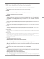
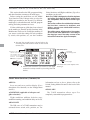
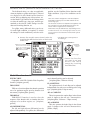
INTRODUCTION
Thank you for purchasing a Futaba® FASSTest-2.4GHz* 14SG series digital proportional R/C system. This
system is extremely versatile and may be used by beginners and pros alike. In order for you to make the
!"#
$
%&
*FASSTest: Futaba Advanced Spread Spectrum Technology extend system telemetry
'(
change without notice.
% %) hobby’s “off season” to ensure safe operation.
IN NORTH AMERICA
+ % & + ,0%3 ! " 56
6 7 8 ,0%3 system and is updated regularly. Any technical updates and US manual corrections will be available on this
"
information on contacting us via email for the most rapid and convenient response.
'9;
<
!
9
=
are available Monday through Friday 8-5 Central time to assist you.
FOR SERVICE ONLY:
Futaba Service Center
@BBDE'%,
&JK,LDD
Phone: 217-398-0007
www.futaba-rc.com/service.html
Email: [email protected]
FOR SUPPORT :
(PROGRAMMING AND USER QUESTIONS)
+)
566
Fax: 217-398-7721
Phone: 217-398-8970 option 2
OUTSIDE NORTH AMERICA
+
or service needs.
+Y
sold in North America only. Products purchased elsewhere may vary. Always contact your region’s support
center for assistance.
4 <Introduction>
,7
#$
in any application other than the control of models for hobby and recreational purposes. The product is
([
\67]
such purposes.
2. Exportation precautions:
#$<8
58
(8+
8
Y immediately to determine if such export regulations have been met.
#$^
_87&\
87Y
@ [ ( ) Y
( warranty.
Compliance Information Statement (for U.S.A.)
7&\`BBL%j,q
&&\=()
#,$7
#D$ 7 operation.
The responsible party of this device compliance is:
Futaba Service Center
@BBDE'%,&JK,LDD^%
7_J#D,`$@{L5L{`B_5)|5#%$
7_J#D,`$@{L5BBB`_5)|5#%$
7 \j\& %_J !5 Futaba Corporation of America is voluntarily participating in an industry-wide program to collect
!
^ %7 \j\& !5
.
#^%$
You may contact your local recycling center for information on where to return the spent battery. Please
,5LBB5Lj77_\~ E& & America's involvement in this program is part of its commitment to protecting our environment and
conserving natural resources.
\j\&!\j
\
&
<Introduction>
5
Federal Communications Commission Interference Statement (for U.S.A.)
7
&j
to Part 15 of the FCC Rules. These limits are designed to provide reasonable protection against harmful
interference in a residential installation.
7
)
--Reorient or relocate the receiving antenna.
55
--Consult the dealer or your Futaba Serivce center for help.
CAUTION:
To assure continued FCC compliance:
8
Exposure to Radio Frequency Radiation
7
&&\8DB
maintained between the antenna of this device and all persons.
75(
Meaning of Special Markings
Pay special attention to safety where indicated by the following marks:
DANGER5+
6(
carried out properly.
WARNING5+
(
(
physical damage is high.
CAUTION 5 + (
(
= Prohibited
= Mandatory
Warning: Always keep electrical components away from small children.
FLYING SAFETY
WARNING
7
)
Have regular maintenance performed. Although your 14SG protects the model memories with
5__+\=[
#$
transmitter still should have regular checkups for wear and tear. We recommend sending your system
% & 5
5 ! service.
6 <Introduction>
NiMH/NiCd Battery
Charge the batteries!#%&E&$
<
7,0%395
during the session pay attention to the duration of usage.
\##
!"
#E
!
!
#
!""
#E!
"G
"\#"E
Where to Fly
We recommend that you fly at a recognized model airplane flying field. You can find model clubs
! ^% [
Aeronautics.
~
[#[$DqBB
7
newcomer training are available. Contact the AMA at the address or toll-free phone number below.
Academy of Model Aeronautics
q,K,_['
[E0`@BD
7#LBB$0@q5{DKD
8#`Kq$DL{50D0L
or via the Internet at http:\\www.modelaircraft.org
!
" \# as well as the presence and location
j
vicinity.
<Introduction>
7
NiMH/NiCd Battery Safety and Handling instructions
IMPORTANT!
Use only the Futaba special charger included with this set or other chargers approved by Futaba to
charge the NiMH batteries in the T14SG transmitter included with this set.
It is important to understand the operating characteristics of NiMH/NiCd batteries.Always read the
E[6E&
!
surroundings and possibly result in a FIRE!
IMPORTANT PRECAUTIONS
Do not attempt to disassemble NiMH/NiCd packs or cells.
Do not allow NiMH/NiCd cells to come in contact with moisture or water at any time.
E[6E&
Do not leave a NiMH/NiCd battery unattended at any time while being charged or discharged.
'E[6E&E=7E[6E&
E[6E&'E[6E&
!
\6
&5Y[!
' E[6E& ,& #&
$
Do not allow NiMH/NiCd cells to overheat at any time! Cells which reach greater than 140 degrees
#KB&$
NiMH/NiCd cells will not charge fully when too cold or show full charge.
excessively hot disconnect the battery from the charger immediately!! Always inspect a battery which
5
in any way.
Do not use a NiMH/NiCd battery if you suspect physical damage has occurred to the pack. Carefully
!
'=E=7
9
!
5@B
'
Do not discharge NiMH/NiCd batteries at currents which exceed the discharge current rating of the
battery.
Always store NiMH/NiCd cells/packs in a secure location away from children.
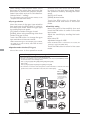
Secure Digital (SD) Memory Card Handling Instructions
!""$
Never remove the SD card or turn off power
while entering data.
Never store the SD card where it may be
( ' 8 %' excessive humidity or corrosive environments.
8 <Introduction>
' 8 %' !
Always hold the SD card by the edges during
installation and removal.
j %' direction.
"\#
7 )
,+!
6
2. Turn on the transmitter power and allow your transmitter to reach its home screen.
@&
4. Turn on your receiver power.
q7
9
the problem.
7%(7
67!
K%
7. Complete a full range check.
L ! ! your motor/engine.
9. Turn off receiver power.
10. Turn off transmitter power.
5 5 8
(
Q"
##
\
"#"
"
!!LEBGG!
In order to maintain complete control of your aircraft it is important that it remains visible at all
times
('
!
#
" L # \#"E '
" Water or moisture may enter the transmitter through the antenna or stick
openings and cause erratic operation or loss of control. If you must fly in wet weather during a
E lightning is expected.
<Introduction>
9
BEFORE USE
Features
FASSTest system
The T14SG transmitter has adopted the newly developed bidirectional communication system
"FASSTest".Data from the receiver can be checked in your transmitter. FASSTest is a maximum 14
channels (linear 12 channels + switch 2 channels) 2.4GHz dedicated system.
S.BUS2 system
By using the S.BUS2 system multiple servos, gyros and telemetry sensors are easily installed with a
minimum amount of cables.
Model types
Six swash types are available for helicopters. Six types of main wings and three types of tail wings are
available for airplanes and gliders. Functions and mixing functions necessary for each model type are set in
advance at the factory.
Data input
Large graphic LCD and new type Touch Sensor substantially improve ease of setup.
Stick
Improved feel, adjustable length and tension.
Ni-MH battery
T14SG is operated by a 6.0 V/1,800 mAh Nickel-Metal Hydride battery.
SD card (Secure Digital memory card) (Not included)
Model data can be saved to an SD card (SD:32MB-2GB SDHC:4GB-32GB). When T14SG transmitter
%'
Edit button
Two edit buttons are provided, and the operating screen can be immediately “Returned” to the HOME
screen during operation. Setting operation can be performed easily by combining this button with a touch
sensor.
Vibration function
Selects a function that alerts the operator to various alarms and timers by vibrating the transmitter in
addition to sounding a buzzer.
10 <Before Use>
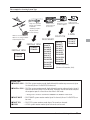
2
7"
#%($
Your 14SG includes the following components:
7,0%3
\`BBL%j\
7q,LBBjE[
&
J57DD,BBj67D,`BBjJ
!
%
E!
*The set contents depend on the type of set.
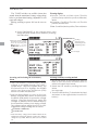
Transmitter T14SG
(2-stick, 14-channel, FASSTest-2.4G system)
Transmitting frequency: 2.4GHz band
%
)%%7,0&%%7,D&%%7[^J7%%7`&%5%%
+
)KB7q,LBBjE[
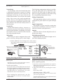
Receiver R7008SB
(FASSTest-2.4G system, dual antenna diversity, S.BUS system)
+)@``0
_%&#,$
%Y)B{L8,LK8BqK#D0{80`@8,0@$
Weight: 0.38 oz. (10.9g)
(*1) When using ESC's make sure that the regulated output capacity meets your usage application.
Note: The battery in the T14SG transmitter is not connected to the battery
connector at initial. Please connect the battery connector before use.
<Before Use>
11
The following additional accessories are available from your dealer. Refer to a Futaba catalog
for more information:
7q,LBBj7
!5#,LBB$E[
!
8
8
7DD,BBj67D,`BBj7J
!
8
spacer. However, charge with the charger only for LiFe.
75
by placing the instructor on a separate transmitter. Note that the T14SG transmitter may be
connected to another T14SG system, as well as to any other models of Futaba transmitters. The
T14SG transmitter uses one of the three cord plug types according to the transmitter connected.
(Refer to the description at the TRAINER function instructions). The part number of this cord is:
^7[00Bq
%5!+
the model and the purpose of using you. If you utilize a S.BUS system, you should choose a S.BUS
servo. An analog servo cannot be used if "FASSTest12CH mode" is used.
7
5 Y communication system and to acquire the information from a model high up in the sky.
[Temperature sensor : SBS-01T] [Altitude sensor : SBS-01A] [RPM sensor magnet type : SBS01RM][RPM sensor optical type : SBS-01RO] [GPS sensor : SBS-01G] [Voltage sensor : SBS01V]
E!5!
7,0%3
!
99
~58538~5
a heavy-duty version with heavier wire, are available to aid in your larger model and other
installations.
3
5
35
(
head speed regardless of blade pitch, load, weather, etc.
\ 5 (Receivers for FASSTest and FASST,S-FHSS types are available.)
=&5&\5DBBBE[6E&76\j
&
12 <Before Use>
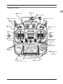
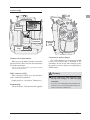
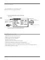
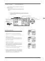
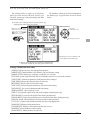
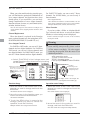
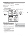
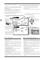
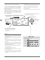
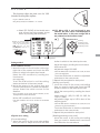
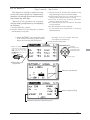
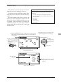
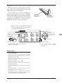
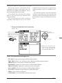
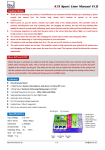
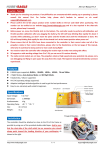
Transmitter controls
●Antenna
●Monitor LED
●Volume(LD,RD)
●Switch(SC,SD,SG,SH)
●Switch(SA,SB,SE,SF)
●Slide Lever(LS)
●Slide Lever(RS)
●Stick
●Stick
(J2)
(J3)
(J4)
(J1)
●HOME/EXIT
Button
●U.MENU/MON.
(User Menu/
Servo Monitor)
ࠉButton
●Digital Trim
(T1,T2)
●Digital Trim
(T3,T4)
●SensorTouchTM
(SYS,LNK,
MDL,RTN,S1)
●Neck Strap Attachment
●Power Switch
*It slides upwards and turns on.
●LCD
●Battery Cover
<Before Use>
13
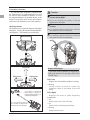
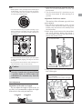
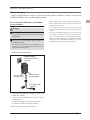
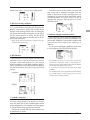
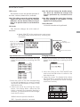
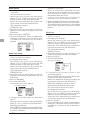
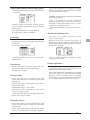
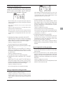
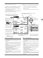
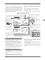
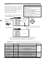
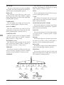
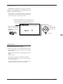
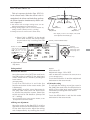
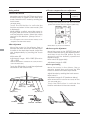
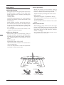
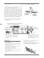
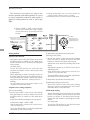
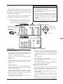
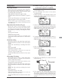
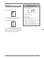
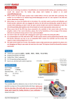
Transmitter's Antenna:
As with all radio frequency transmissions,
the strongest area of signal transmission is from
the sides of the transmitter's antenna. As such,
the antenna should not be pointed directly at the
easily move the antenna to correct this situation.
Caution
Please do not grasp the transmitter's
#\#"E
Doing so may degrade the quality of the RF
transmission to the model
Do not carry the transmitter by the
antenna.
Rotating antenna
The antenna can be rotated 90 degrees and angled
90 degrees. Forcing the antenna further than this
can damage it. The antenna is not removable.
There is the danger that the antenna wire will break
and operation will become impossible.
Do not pull the antenna forcefully.
There is the danger that the antenna wire will break
and operation will become impossible.
90°
90°
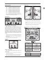
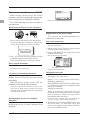
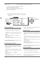
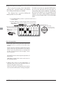
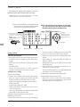
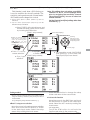
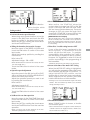
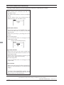
Low power
Monitor LED display
High power
High power
The status of the transmitter is displayed by
LED at the bottom left and right sides of the
"T14SG" logo.
LED (Left)
Displays the "non-default condition" warning.
If you have a transmitter
at an angle of a figure, an
antenna will be good to use
it, bending 90 degrees.
It is not good for there to
be a model on flight in the
direction tip of an antenna.
14 <Before Use>
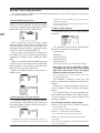
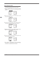
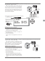
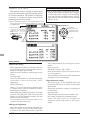
LED (Right)
Displays the state of radio frequency
transmission.
!
!
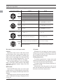
Switch (SA-SH)
Slide Lever
"#$
"% &'$(%("
" &'$(%()
"* &'$(%()
"+ &'$(%("
", &'$(%("
" &-$(%()
". &'$(%("
"/ &-$(0!()
~=E6=5
the setting screen of the mixing functions.
LS
RS
Digital Trim
LS (Left), RS (right):
The slide lever LS and RS offer analog input.
T4
T2
T3
T1
*The T14SG transmitter beeps when the lever comes to the
center.
~ direction on the setting screen of mixing functions.
Digital Trim T1, T2, T3 and T4:
This transmitter is equipped with four (4)
digital trims. Each time you press a trim button,
the trim position moves one step. If you continue
pressing it, the trim position starts to move faster.
In addition, when the trim position returns to
~
monitor trim positions by referencing the LCD
screen.
~
on the home screen on the T1-T4 setting screen within the
linkage menu.
Note: The trim positions you have set will be stored in the
non-volatile memory and will remain there.
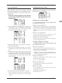
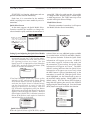
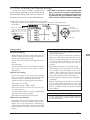
HOME/EXIT and U.MENU/MON. Button
HOME/EXIT
Button
U.MENU/MON.
Button
Volume
RETURN
HOME/EXIT:
Return to the previous
screen
Return to the Home
screen
Press
Press and hold
LD
RD
Volume LD and RD:
The volume LD and RD knobs allow for
analog input.
*The T14SG transmitter beeps when the volume knob
reaches the center position.
~8
It pushes from HOME
screen.
To TELEMETRY display
Push and hold for
one (1) second from
HOME screen.
Key lock On or Off
U.MENU/MON.:
Press
To SERVO MONITOR display
Press and hold
To User Menu display
<Before Use>
15
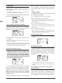
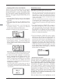
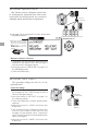
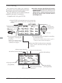
Touch sensor operation
Data input operation is performed using the touch sensor.
SensorTouch™ operation
s3HORTgTAPg
Condition
Working
If the screen has more than one page. (Ex. P-MIX screen)
S1
RTN
The cursor moves to the top of next page.
If the screen have only one (1) page.
The cursor moves to the top of page.
If inputting data while the cursor is blinking.
The input data is canceled.
At the moving cursor mode.
Change to the input data mode.
While in the data input mode.
Changes to the moving cursor mode.
While inputting data while cursor is blinking.
The data is entered.
SYS
At all screens
Jump to System Menu screen directly.
LNK
At all screens
Jump to Linkage Menu screen directly.
MDL
At all screens
Jump to Model Menu screen directly.
At the HOME screen
Key lock On or Off
While inputting data with no blinking cursor.
Reset to the initialized value.
Lightly circling the outside edge of the RTN button.
The cursor moves accordingly.
During the data input mode.
Increases or decreases values accordingly.
s4WOSHORTgTAPSg
s4OUCH AND HOLD FOR
one (1) second.
S1
RTN
s3CROLLING
Outline
OF
“RTN”
Movement of cursor, value input or mode
selection:
Movement of the cursor on the menu screen
and movement of the cursor among items on a
setup screen can be controlled by scrolling your
~ also go to the next page, if there is a next page.
This scrolling technique is also used for data
input, value input, mode selection, and similar
operations. Examples include: Value, ON, OFF,
INH, ACT, etc.
RTN button:
Touch the RTN button when you want to open
a setup screen or to switch between cursor move
mode (reverse display) and data input mode (box
display).
This button can also be used as the enter button
screen, etc.
16 <Before Use>
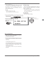
S1 button:
When there is a next page on a menu screen or
setup screen, you can go to that page by touching
the S1 button. In this case, the cursor moves to
the screen title item of the page.
Exiting setup screen:
To end the operation on a setup screen and
return to the menu screen, move the cursor to the
screen title item and touch the RTN button.
To return to home screen directly, touch the S1
button for 1 second.
Alternatively, move the cursor to the screen
title item and touch the RTN button to return to
the home screen from a menu screen.
Note:
%)&
the RTN button. The sensors may mis-read your touch as
a reverse rotation if the circle is smaller, or performed on
the inside edge of the RTN button.
1/22
2%2 3 # - # 3 2%2 3 22 $ Adjustment of stick lever tension
The tension of the self-return type stick lever
can be adjusted.
* The SensorTouch™ may not operate smoothly if your
hand is touching the surrounding case parts. Please make
sure that the tip of your finger is actually operating the
SensorTouch™.
14 ! !!54$
! !
!
-544!!6
7 0 14
!
5$
s)TISONLYTHEMODE
*If the SensorTouch™ does not register your input, please
try again after lightly tapping your finger on the sensor
once again.
* Do not operate the SensorTouch™ while wearing gloves.
The SensorTouch™ may not work correctly.
s3IDE#OVER
Caution
The touch sensor may not operate
correctly if spark noise is generated from
a gasoline engine, etc. Please remove the
transmitter to a location away from the
noise source.
'8 ! !
$
*It is difficult to remove rear grips from the central
site of a transmitter.
Therefore, remove from the outside of rear grips.
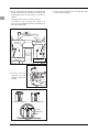
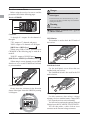
Stick Adjustment
Adjustment of the stick lever length
It removes
from here
~ ( ! you like. It is recommended to adjust the length
of the sticks in line with your hand size.
Lever Head
A
Lever Head
B
s2EAR'RIP
s2EAR'RIP
<Before Use>
17
;8!
$:
$$ : :
*Turning the screw clockwise increases the tension.
*%8#<& < !4$
s3TICK4ENSION*
(Mode 2)
s3TICK4ENSION*
(Mode 1/2)
s3TICK4ENSION*
(Mode 1/2)
s3TICK4ENSION*
(Mode 1)
# : =
+ screw is clockwise.
Stick tension maximum
+ screw is counter-clockwise.
Stick tension minimum
A screw is kept
from coming out
from a line.
*The screw will touch the case.
18 <Before Use>
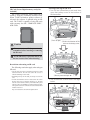
9%:!43
$
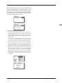
SD Card (Secure Digital memory card) (Not
included)
The T14SG transmitter model data can be
stored by using any commonly found SD card.
When T14SG transmitter update software is
released, the software is updated using an SD
card. The T14SG is capable of using SD cards
with a memory size SD : 32MB-2GB SDHC :
4GB-32GB.
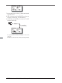
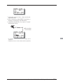
Inserting/removing the SD card
1# ! $ $ ! !
① Push to open.
Caution
②Slide in the direction of the
arrow on the battery cover.
Be sure to turn off the power to the
transmitter before inserting or removing
the SD card.
As the SD card is a precision device, do
not use excessive force when inserting.
Restrictions when using an SD card
The following restrictions apply when using an
SD card:
*The SD card must first be initialized using the T14SG
dedicated format. The SD card cannot be used as is
without formatting to the T14SG.
*Initializing destroys all the data previously saved on the
card.
*An SD card formatted to the T14SG cannot be written
+&
<_87
must be converted and written by the Futaba File System
This special conversion software can be downloaded from
Futaba's web site at:
http://www.futaba-rc.com/software-updates.html
③ Battery
ery cover will open downward.
d wn
do
nwa
ward
rd
d
-#"+>
SD card slot
<Before Use>
19
[Inserting the card]
# "+ !
+
[Removing the card]
7"+$4
! !
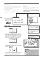
'* SD card initialization
To use an SD card with the T14SG, the card
=
does not have to be reformatted. Formatting is
performed by the T14SG.
?<0
#%#@7"+!
#1;".4 $35 Do not format a card containing
important data.
[Formatting procedure]
1< "+ "+ #1;".
-# # 1 ; " . $ 7 !#1;".4
$$
'< #1;". !4 ! ?0%#@ #
# !4 ! ?*%*,)@ #
;0?A,"@#
* Formatting starts. During formatting, the [NOW
FORMATTING...] message is displayed.
*When formatting is completed, The [FORMAT
COMPLETED] message is displayed. Depending on the
card capacity and speed, formatting may take as long as
several minutes.
20 <Before Use>
[IMPORTANT] Do not turn off the power until
the [FORMAT COMPLETED] message is
displayed.
9,! # SD card reader/writer
Saving model data and update files (released
from Futaba) to the SD card from your own
PC, you can transfer those file to your T14SG
transmitter. Equipment for reading and writing
SD cards is available at most electronics stores.
Stored data
If you have a problem saving or reading data
after a long period of use, we suggest obtaining a
%'
*Futaba is not responsible for compensating any failure or
damage to the data stored in the memory card. As such,
we suggest that you maintain a backup of your important
data contained on your SD card.
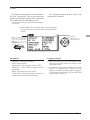
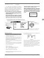
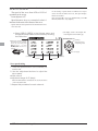
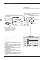
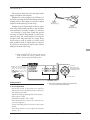
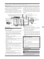
Connector/Plug
Trainer
Connector
S.BUS (S.I/F)
Connector
Charge
Plug
Earphone
Plug
Connector for trainer function
When you use the trainer function, connect the
optional trainer cable between the transmitters
for teacher and student.
~7
screen in the System menu.
S.BUS connector (S.I/F)
When setting an S.BUS servo and telemetry
sensor, connect them both here.
#%
@5
~5$
Earphone plug
It is not used now. (The function after upgrade)
Connector for battery charger
This is the connector for charging the NiMH
7q,LBBj transmitter. Do not use any other chargers except
the attached special charger corresponding to
NiMH battery.
Warning
Do not connect any other chargers except
the special charger to this charging
connector.
!E[
7q,LBBj
transmitter, you can use the optional quick charger CR2000 corresponding to NiMH battery.
<Before Use>
21
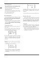
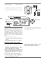
Installation and Removal of the HT5F1800B
Transmitter Battery
Attachment of the battery
1 " ! ! $
Battery Removal
Note: If you remove the battery while the
power is on, the data you have set will not
be saved.
1$ -+ '
$
!
;* !$
Warning
Be careful not to drop the battery.
① Push to open.
②Slide in the direction of the
arrow on the battery cover.
Never disconnect the battery connector
from the T14SG transmitter after
turning off the power until the screen is
completely blank and the transmitter has
shut down completely.
* Internal devices such as memories may be damaged.
* If there is any problem, the message "Backup Error"
will be shown the next time when you turn on the
power of the transmitter. Do not use the transmitter as
it is. Send it to the Futaba Service Center.
ery cover will open d
ownwar
ward
d
③ Battery
downward.
-< '* Battery
Connector
Battery
release tab
;* !$
22 <Before Use>
When exchanging for the LiFe battery
(FT2F2100B/FT2F1700B) of an option.
The battery state inside T14SG
Attachment of the battery
1#1;"./#91BCC!
- % ) $ 1;". ! >
NiMH HT5F1800B
LiFe SPACER
LiFe FT2F2100B/1700B
LiFe SPACER
Charge of a LiFe battery
$ '%) $
>
Note: LiFe battery cannot be charged with the
charger of 14SG attachment.
Be sure to remove a battery from T14SG and
to charge from the charger only for LiFe.
A LiFe
battery is
removed
from T14SG.
2P connector is
removed from T14SG.
;-
)
Balance charge
is carried out from the charger only for LiFe.
LiFe
Battery
The balance charge connector is not connected
in the state where the battery is set to a transmitter.
9* !$
6.T14SG is turned on and [LINKAGE
MENU]=>[WARNING]=>[LOW BATTERY] is
called.
7. It changes into 6.0V from 5.6V.
*About low battery voltage, all the models included in
one transmitter are changed in common. It cannot set to
different voltage for every model. Moreover, data reset is
not carried out.
Warning
Follow the manual of a LiFe battery.
Don't charge the LiFe battery with the
NiMH charger of 14SG attachment.
* Be sure to remove from T14SG and to charge with the
charger only for LiFe.
Be sure to change the voltage of LOW
BATTERY WARNING into 6.0V from
5.6V
<Before Use>
23
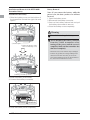
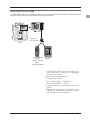
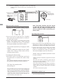
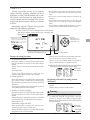
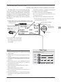
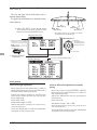
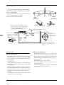
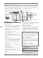
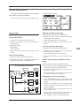
Receiver nomenclature
Before using the receiver, be sure to read the
precautions listed in the following pages.
Receiver R7008SB
Danger
Don't connect a connector, as shown in a
#E
*It will short-circuit, if it connected in this way. A short
circuit across the battery terminals may cause abnormal
Warning
S.BUS2 connectors
Don't connect an S.BUS servo / gyro to
S.BUS2 connector.
Connector
"1 through 6": outputs for the channels 1
through 6
£`6j£)`
"8/SB": outputs of 8 channels or S.BUS port.
[S.BUS Servo S.BUS Gyro ]
*When using 8/SB as S.BUS, you have to set
CH MODE of the following page to mode B or
mode D.
"S.BUS2": outputs of S.BUS2 port.
[S.BUS2 Servo S.BUS2 Gyro Telemetry Sensor ]
*When using 9 or more channels, use an S.BUS
\`BBL%j!
to your transmitter.
LED Monitor
This monitor is used to check the CH mode of
the receiver.
Link/Mode Switch
Use the small plastic screw driver that was
included with your receiver.
The Link/Mode Switch is also used for the CH
mode selection.
+
Connector insertion
Firmly insert the connector in the direction
%j^%D
it 90 degrees.
Danger
5HFHLYHU
Do not connect either a switch
or battery in this manner.
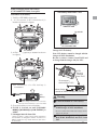
24 <Before Use>
−
Extra Voltage Connector
Use this connector when using a voltage
telemetry device to send the battery voltage (DC0
`B$
~_8
#&5\E5`BB$^7[qqq,
~ ! 8
connector to the External voltage connector.
Danger
Don't touch wiring.
* There is a danger of receiving an electric shock.
Do not short-circuit the battery terminals.
* A short circuit across the battery terminals may cause
Please double check your polarity ( + and
− ) when hooking up your connectors.
* If + and − of wiring are mistaken, it will damage,
ignite and explode.
¤\`BBL%j&¥
1
)D0 ECCB"
- # )D0 ),+
D !
'#),+ $ ; , $ 0D) 5!
9 7 ! $ 4 $ 0D
) !-
F ! ),+
E
$
*
0
Don’t connection to Extra Voltage before
turning on a receiver power supply.
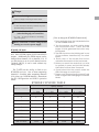
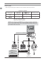
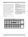
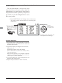
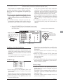
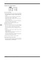
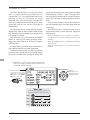
R7008SB CH Mode
7 \`BBL%j unit. It has 8 PWM outputs, S.BUS and S.BUS2
outputs. Additionally the PWM outputs can be
changed from channels 1-8 to channels 9-14. If
you only desire to use it as an 8 channel receiver
(without S.BUS), it can be used without any
setting changes.
The T14SG has the ability to link to two
\`BBL%j = channels 1-8 and the other outputting channels
9-14 giving you 14 PWM channels. Instructions
for this configuration and S.BUS operation
follow.
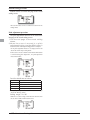
R7008SB CH MODE TABLE
Setting channel
Receiver connector
Mode A
1 ∼ 8CH
Mode B
1 ∼ 7CH
Mode C
9 ∼ 14CH
Mode D
9 ∼ 14CH
1
1
1
9
9
2
2
2
10
10
3
3
3
11
11
4
4
4
12
12
5
5
5
13
13
6
6
6
14
14
7/B
7
7
-
-
8/SB
8
S.BUS
-
S.BUS
Red LED blink
1time
2time
3time
4time
<Before Use>
25
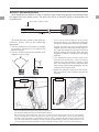
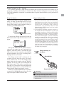
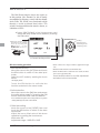
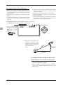
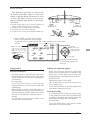
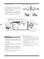
Receiver's Antenna Installation
7\`BBL%j8Y
has adopted a diversity antenna system. This allows the receiver to obtain RF signals on both antennas and
5
*Must be kept as straight as possible.
Antenna
Coaxial cable
R7008SB Receiver
To obtain the best results of the diversity
function, please refer to the following
instructions:
1#! $
$ -# $GC
Antenna
# 4 !
!$ $ !!$ ) ! !
:<
$
! # H
' # ! $ !
!4 !4
#5$
4 ;I$!!4
,"*4 ! $ Antenna
*The two antennas should be placed at 90 degrees to each other.
*The Illustration demonstrates how the antenna should be placed.
*Receiver Vibration and Waterproofing: The receiver contains precision electronic parts. Be sure to avoid vibration,
shock, and temperature extremes. For protection, wrap the receiver in foam rubber or other vibration-absorbing
materials. It is also a good idea to waterproof the receiver by placing it in a plastic bag and securing the open end of the
bag with a rubber band before wrapping it with foam rubber. If you accidentally get moisture or fuel inside the receiver,
you may experience intermittent operation or a crash. If in doubt, return the receiver to our service center for service.
26 <Before Use>
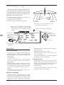
Safety precautions when you install
receiver and servos
Mounting the Servo
Wood screw
2.3-2.6mm nut
washer
Rubber
grommet
Brass eyelet
Rubber
grommet
Brass eyelet
Servo mount
Servo mount
2.3-2.6mm screw
(Airplane/Glider)
(Helicopter)
Warning
Connecting connectors
Be sure to insert the connector until it
stops at the deepest point.
How to protect the receiver from vibration
and water
Servo lead wires
To prevent the servo lead cable from being
broken by vibration during flight, provide a
little slack in the cable and fasten it at suitable
points. Periodically check the cable during daily
maintenance.
Wrap the receiver with something soft
such as foam rubber to avoid vibration.
If there is a chance of getting wet, put the
receiver in a waterproof bag or balloon to
avoid water.
Receiver's antenna
Never cut the receiver's antenna. Do not
bind the receiver's antenna with the cables
for servos.
Margin in the lead wire.
Fasten about 5-10cm
from the servo outlet so
that the lead wire is neat.
Locate the receiver's antenna as far as
possible from metals or carbon fiber
components such as frames, cables, etc.
*Cutting or binding the receiver's antenna will reduce the
radio reception sensitivity and range, and may cause a
crash.
Mounting the power switch
When mounting a power switch to an airframe,
make a rectangular hole that is a little larger than
the total stroke of the switch so that you can turn
the switch ON/OFF without binding.
Avoid mounting the switch where it can be
covered by engine oil and dust. In general, it is
recommended to mount the power switch on the
Servo throw
Adjust your system so that pushrods will
not bind or sag when operating the servos
to the full extent.
*If excessive force is continuously applied to a servo, the
servo could be damaged due to force on the gear train
and/or power consumption causing rapid battery drain.
Mounting servos
Use a vibration-proof rubber (such as
rubber grommet) under a servo when
mounting the servo on a servo mount. And
be sure that the servo cases do not touch
directly to the metal parts such as servo
mount.
*If the servo case contacts the airframe directly, vibration
will travel to and possibly damage the servo.
<Before Use>
27
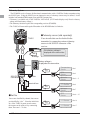
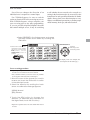
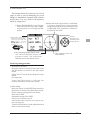
S.BUS/S.BUS2 Installation
7%j^%6%j^%D
7
with models that use a large number of servos. In addition, the wings can be quickly installed to the fuselage
without any erroneous wiring by the use of only one simple wire, even when there are a large number of
servos used.
¦<%j^%6%j^%D8
¦7%j^%6%j^%DY#%7,0%3$
¦7%j^%6%j^%D
#&$8
S.BUS Glider usage example
Receiver: R7008SB
Servo: S3172SV×9 ( Optional )
HUB×4 ( Optional )
Throttle servo: BLS173SV ( Optional )
Battery: FR2F1800 ( Optional )
S.BUS Aerobatic plane usage example
Switch: HSW-L
Receiver: R7008SB
Aileron servo: BLS174SV×2 ( Optional )
HUB×3 ( Optional )
Rudder Servo: BLS175SV×1 ( Optional )
Elevator servo: BLS173SV×2 ( Optional )
28 <Before Use>
S.BUS Wiring example
Receiver *When using 8/SB as S.BUS, you must set the receiver to
Mode B or Mode D. See R7008SB CH MODE TABLE.
●S.BUS Servo
Since the channel number is memorized by
the S.BUS itself, any connector can be used.
When the SBD-1 (sold separately) is used,
ordinary servos can be used with the
S.BUS system.
%DWWHU\
6%86
3RUW
6%
6ZLWFK
*<
([WHQVLRQ
FRUG
7HUPLQDOER[
●7HUPLQDOER[
Four connectors can be inserted
+8%
+8%
+8%
Warning
Power supply
Please make sure that you
use a battery that can deliver
enough capacity for the
number and kind of servos
used. Alkaline batteries
cannot be used.
6%866HUYR
+8%
ق$QRWKHUSRZHUVXSSO\ك
6ZLWFK
+8%
●When separate power supply used
+8%
%DWWHU\
When a large number of servos are used or
when high current servos are used, the servos
can be driven by a separate power supply by
using a separate Power Supply 3-way Hub.
6%866HUYR
Green
+8%
Used when using a separate
power supply battery.
+8%
Orange
Three connectors can be
inserted.
<Before Use>
29
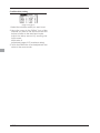
S.BUS2 System
When using the S.BUS2 port, an impressive array of telemetry sensors may be utilized.
S.BUS2 TABLE
Receiver port
S.BUS Servo
S.BUS Gyro
S.BUS2 Servo
S.BUS2 Gyro
Telemetry sensor
S.BUS
○
○
×
S.BUS2
× (※)
○
○
(※)Don't connect S.BUS Servo,
S.BUS Gyro to S.BUS2 connector.
S.BUS servos and gyros and S.BUS2 servos and gyros must be used in the
correct receiver ports. Please refer to the instruction manual to make sure
you connect to the correct one.
&+0RGHLVVHWWR0RGH%>'@
6%86
3RUW
6%
6%86
3RUW
+XE
+XE
6%866HUYR
6%86VHUYR
&RQQHFWLRQLVSRVVLEOH
6%86J\UR
&RQQHFWLRQLVSRVVLEOH
7HOHPHWU\VHQVRU
&RQQHFWLRQLVLPSRVVLEOH
30 <Before Use>
+XE
+XE
6%866HUYR
7HOHPHWU\
6HQVRU
6%86VHUYR
&RQQHFWLRQLVLPSRVVLEOH
6%86
*<52
ٔ
5XGGHU6HUYR
S.BUS/S.BUS2 device setting
S.BUS/S.BUS2 servos or a telemetry sensor can be connected directly to the T14SG. Channel setting and
other data can be entered for the S.BUS/S.BUS2 servos or sensors.
76*
'3 A3
6%866%86
GHYLFH
6%866%86
6HUYR
5HFHLYHUV
%DWWHU\
7HOHPHWU\VHQVRU
1 * "8" '3 A3
>
-#!$
'*$
"&"!0→"8""
"&)0→"
; ! 9#
"8" 4 ! "8"
<Before Use>
31
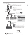
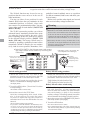
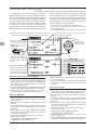
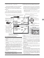
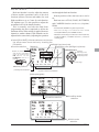
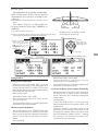
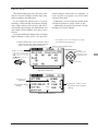
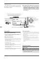
Telemetry System
7\`BBL%j5%%7
the S.BUS2 port. Using the S.BUS2 port an impressive array of telemetry sensors may be utilized. It also
includes both standard PWM output ports and S.BUS output ports.
* Telemetry is available only in the FASSTest 14CH mode. (12CH mode displays only Receiver battery
voltage and Extra battery voltage.)
7
#\`BBL%j$
77,0%3!'\`BBL%j!
●Telemetry sensor (sold separately)
76*
Info
Signal
Info
Your aircrafts data can be checked in the
transmitter by connecting various telemetry
sensors to the S.BUS2 connector of the
receiver.
Drive battery voltage is
displayed at the transmitter.
voltage
Receiver
Battery voltage is
displayed at the transmitter.
Info
6%86
&RQQHFWRU
+8%
6ZLWFK
Info
7HUPLQDOER[
7HPSHUDWXUH
6HQVRU
Slot 1
530
6HQVRU
Slot 2
$OWLWXGH
6HQVRU
Slot 3 ∼ 5
6HQVRU
Slot 6
Info
+8%
●Slot No.
Servos are classified by channel, but sensors
are classified by “slot” . Since the initial slot
No. of the T14SG is preset at each sensor,
the sensors can be used as is by connecting
them. There are 1 31 slots.
32 <Before Use>
9ROWDJH
6HQVRU
Slot 7
*36
6HQVRU
Slot 8 ∼ 15
6HQVRU
Slot 16
6HQVRU
Slot 17
Info
+8%
BASIC OPERATION
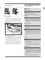
Battery Charging
Before charging batteries, read the "Cautions for handling battery and battery charger" in the section
"NiMH/NiCd Battery Safety and Handling Instructions".
How to charge the NiMH battery HT5F1800B
for the transmitter
*Battery charging will not automatically stop. Remove the
battery and transmitter from the charger and remove the
charger from the wall socket.
*It is recommended to reactivate the battery by cycling
several times if the battery has not been used for a long
period.
Danger
The NiMH battery HT5F1800B is only for
your T14SG. Do not use this battery for other
equipment.
Be sure to use the attached special charger to
charge the battery.
*In the case of NiMH/NiCd batteries, you may find poor
performance of the battery if you have used the battery
only for a short period or if you repeat charging while the
battery is not fully discharged. It is suggested to discharge
the battery to the recommended level after use. It is also
recommended to charge the battery just before use.
*If you take the NiMH battery HT5F1800B out of the
transmitter, you can use the optional quick charger CR-2000
corresponding to NiMH battery.
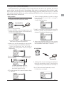
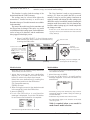
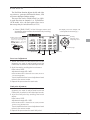
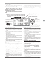
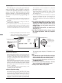
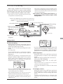
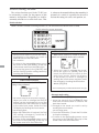
[Method of charging battery]
Special charger
*Connect to AC outlet
specified.
Receiver Batt.
Charging display
Transmitter Batt.
Charging display
To T14SG charge
connector
1. Connect the special charger to the wall
socket (AC outlet).
2. Connect the connectors to the T14SG
charging jack.
&J_'
*Turn off the transmitter while charging the battery.
3. Remove the battery after 15 hours.
<Basic Operation>
33
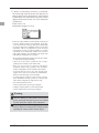
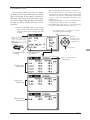
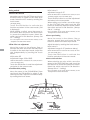
How to turn transmitter power ON/OFF
When turning on the power, the T14SG
transmitter will begin emmiting RF automatically
\
The T14SG transmitter also offers the ability to
auto shut-down.
*below 1/3 stick, the warning display goes off.
When turning on the power of the transmitter
THR Stick Slow
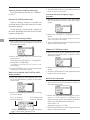
Registration of the user's name
If so desired, the T14SG transmitter can
indicate the owner's name.
1. Turn on the power switch of the transmitter.
7£&_&§\&=E'7=E£
J_'!
User's name setup screen
1. Turn on the power of the transmitter.
*The home screen appears.
2. Lightly touch the SYS button twice rapidly
and the System menu appears.
3. Select [USER NAME] in the System menu and
touch the RTN button.
2. Then, you will see the home screen and the
transmitter begins to emit radio waves.
*The user name set up screen appears.
7J_'
How to stop the transmitter
1. Turn off the power switch of the transmitter.
*The transmitter shuts down at once.
Low battery alarm and auto shut-down
When the battery voltage reaches 5.2V, an
J immediately.
When the battery voltage reaches 3.9V, the
transmitter will be turned off automatically.
*If you do not operate the transmitter (or move a stick,
knob, switch or digital trim) for 30 minutes, the message
£+J_%_7^\E=+=<_\%<7&£
an audible alarm will sound.
Warning display at power ON (Airplane/
Helicopter)
< ! + = the high side (or over 1/3 stick) a warning will be
displayed.
34 <Basic Operation>
Input Box
*Current user name is displayed.
Changing the user name
1. Change the user name as described below:
[Moving cursor in input box]
"?}@?~@4# [Deleting a character]
When [DELETE] is selected and the RTN button
is touched, the character immediately after
the cursor is deleted.
[Adding a character]
When a character is selected from the
character list and the RTN button is touched,
that character is added at the position
immediately after the cursor.
*A name of up to 10 characters long can be entered as the
user name. (A space is also counted as one character.)
2. At the end of input, select [ENTER] and tuoch
the RTN button. (To terminate input and
return to the original state, select [CANCEL]
and touch the RTN button.)
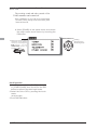
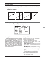
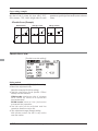
Home screen
^
\7E
button. The setting screen appears.
System timer
Key lock
#!!
the latest reset. (Hour):(Minute)
8 4 touch the RTN button for one second
to reset the system timer.
# "1 $ HOME/EXIT button for one second to
lock/unlock the key operation.
In the key lock mode the key icon is
displayed here.
Up/Down timer (ST1, ST2)
#!$
Touch the RTN button at the [xx]:[xx.
xx] item to start/stop the timer.
8 4 touch the RTN button at the ST1 or ST2
item to call the timer set-up screen.
*See the description at the back of this manual.
User's name
RF indicator
SD card indicator
Battery Indicator
7 reaches 5.2V(Change in
Warning Menu), the alarm
will beep. Land your aircraft
immediately.
Model type
Model Name
#!!
is currently used is
displayed here.
8 highlight this, then
touch the RTN button
to call the model
select set-up screen.
System mode
Model timer
"!%""#1;*/ mode is displayed here.
8 4
then touch the RTN button
to call the frequency set-up
screen.
# ! !
since the latest reset. (each model)
(Hour):(Minute)
8 4
then touch the RTN button for one
second to reset the model timer.
Digital trim (T1 to T4)
#!$$
A$
on the home screen on the
T1-T4 setting screen within the
linkage menu.
2nd Home screen
# # the clock icon to call the
2 nd home screen (large
size timer).
Condition name (Heli/Glider)
< ! 4 ! cursor to the condition name and
touch the RTN button. The condition
name is changed and blinks.
It is possible to operate the digital
trim in all conditions.
VPP condition # (Air)
7
4
# is displayed here.
<Basic Operation>
35
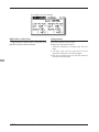
User Menu
A user menu which allows the user to
customize and display frequently used functions
has been added.
1. When the "U.MENU" button is pushed for
two seconds, the user menu appears.
\
_¨7
while the user menu is being displayed.
2. When the cursor highlights the dotted line,
"----------" and the RTN button is touched,
the menu selection screen appears.
3. When the cursor is moved to the setting
that you to set to the user menu and the
RTN button is touched, that setting screen
is added to the user menu.
4. The registered setting screen can be
called by moving the cursor to it and
touching the RTN button.
*When you want to delete an added screen from the user
menu, highlight item you wish to delete, press and hold
the RTN button for one second.
36 <Basic Operation>
Warning
j
Check the battery voltage as often as
possible and try to charge the battery
earlier. If the battery alarm makes a sound,
land your aircraft immediately.
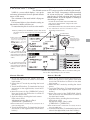
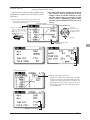
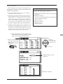
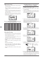
Link procedure (T14SG/R7008SB)
_
'
!'=!
the ID code is stored in the receiver and no further linking is necessary unless the receiver is to be used
with another transmitter. When you purchase additional R7008SB receivers, this procedure is necessary;
otherwise the receiver will not work.
Link procedure
1
!
to each other within half (0.5m) meter.
6. When changing battery fail-safe voltage
from the initial value 3.8V, voltage is
changed here.
%""#0
Less than 0.5 m
2. Turn on the transmitter.
3. Select [SYSTEM] at the Linkage menu and
access the setup screen shown below by
touching the RTN button.
:You can d
do this th
through
h th
the LINK
LINKAGE Menu
and scroll to System and press RTN.
4. When you use two receivers on one model,
you must change from [SINGLE] to [DUAL].
*O nl y tw o receivers can be used. I n
"DUAL", two setting items come out. Input,
respectively.
<+ !
receiver displays.
7.[LINK] is chosen by scrolling and the RTN
button is pushed. The transmitter will emit a
chime as it starts the linking process.
8. When the transmitter starts to chime, power
on the receiver. The receiver should link to
the transmitter within about 1 second.
In "Link" Mode
ID of a Secondary
receiver displays.
Receiver ON
9. If linking fails, an error message is displayed.
Bring the transmitter closer to the receiver
and repeat the procedure above from Step 2.
In DUAL, a primary receiver
is link previously. Next, a
secondary receiver is link.
10. ACT will be chosen if telemetry is used.
It is INH when not using it.
922 "G" general.
<Basic Operation>
37
11. When a telemetry function is enabled,
the receiving interval (down-link interval) of
sensor data can be changed. If a DL interval
is increased, the response of the sensor data
display becomes slower, but stick response
will improve.
Initial value: 1.0s
Adjustment range: 0.1s~2.0s
* If there are many FASSTest systems turned on around your
receiver, it might not link to your transmitter. In this case,
J_'
the receiver might have established a link to one of other
transmitters. This is very dangerous if you do not notice
this situation. In order to avoid the problem, we strongly
recommend you to doublecheck whether your receiver is
really under control by your transmitter by giving the stick
input and then checking the servo response.
*Do not perform the linking operation when the drive motor
is connected or the engine is running.
* When you use two receivers, please be sure to setup a
"primary" and "secondary" in the "dual" mode.
*Since two sets of receivers cannot be individually
recognized without using a "primary" and "secondary"
setup, it is impossible to receive telemetry data correctly.
* You must link one receiver at a time. If both power
supplies to the receivers are switched on simultaneously,
data is received incorrectly by the transmitter.
* If a dual receiver function is used, in order to receive
sensor information correctly by both sets, telemetry data
will be slower compared to a single receiver setup.
* You cannot link three receivers.
J!
J!
J!
Warning
After the linking is done, please cycle receiver
power and check that the receiver to be linked
is really under the control of the transmitter.
Do not perform the linking procedure with
motor's main wire connected or with the engine
operating as it may result in serious injury.
38 <Basic Operation>
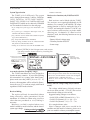
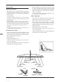
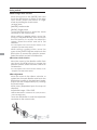
Range Testing Your R/C System
It is extremely important to range check your models prior to each flying session. This enables you to
8(
The T14SG transmitter incorporates a system that reduces its power output and allows you to perform such
a range check.
Range check mode
Range check procedure
We have installed a special "Range check
mode" for doing a ground range check. To access
the "Range check mode" touch and hold the RTN
button while turning on the transmitter. Doing so
+=<_\[='_
1. With the "Range check mode" on, walk
away from the model while simultaneously
operating the controls. Have an assistant
stand by the model to confirm that all
controls are completely and correctly
operational. You should be able to walk
approximately 30-50 paces from the model
without losing control.
2. If everything operates correctly, return to
the model. Set the transmitter in a safe, yet
accessible, location so it will be within reach
after starting the engine or motor. Be certain
the throttle stick is in the low throttle position,
! !
another range check with your assistant
holding the aircraft with the engine running
at various speeds. If the servos jitter or move
inadvertently, there may be a problem. We
H
> !
Look for loose servo connections or binding
pushrods. Also, be certain that the battery
has been fully charged.
The present model
To activate the "Range check mode" touch the
RTN button and the range check mode screen will
appear.
During this mode, the RF power output is
reduced so the range test can be performed. In
addition, when this mode is activated the right
J_'!
and the transmitter gives users a warning with a
beeping sound every 3 seconds.
The "Range check mode" continues for 90
seconds and after that the power will return
to the normal level. To exit the "Range check
£{B£\E3_
&_&§£ RTN button again. This mode is available one
time only so if you need to re-use this function the
E__\ £\!£
Should you require additional time to perform
a range check, highlight Restart before your time
expires and press the RTN button one time.
Range checking on
low power.
About 100 feet
Range check mode
Warning
'
!
*Since the range of the radio waves is short, if the model
is too far from the transmitter, control will be lost and the
model will crash.
<Basic Operation>
39
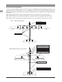
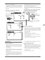
RECEIVER AND SERVO INSTALLATION
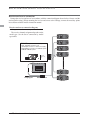
Receiver and servos connection
Connect the receiver and servos in accordance with the connection diagram shown below. Always read the
section [Before using]. When mounting the receiver and servos to the fuselage, connect the necessary points
in accordance with the model's instruction manual.
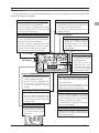
Receiver and servos connection diagram
Always connect the necessary number of servos.
The receiver channel assignment depends on the
model type. See the Servo connection by model
type tables.
R7008SB (output connector section)
sCH1~6: Output connectors 1~6
s"/UTPUTCONNECTORSAND0OWERSUPPLY
s3"/UTPUTCONNECTORSOR3"53SYSTEM
s3"533"53SYSTEM
CH1~8,
S.BUS/(2),
B
Receiver battery
Charging port
Receiver switch
Servos
40 <Receiver and Servo Installation>
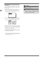
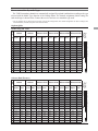
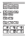
Servo connection by model type
The T14SG transmitter channels are automatically assigned for optimal combination according to the type
selected with the Model Type function of the Linkage Menu. The channel assignment (initial setting) for
each model type is shown below. Connect the receiver and servos to match the type used.
*The set channels can be checked at the Function screen of the Linkage Menu. The channel assignments can also be changed. For
more information, read the description of the Function menu.
Airplane/glider
Normal wing and V-tail
2Aileron
2Aileron+1FLAP 2Aileron+2FLAP 2Aileron+4FLAP 4Aileron+2FLAP
Airplane
Glider
Airplane
Glider
Airplane
Glider
Airplane
Glider
Airplane
Glider
1
Aileron
Aileron
Aileron
Aileron
Aileron
Aileron
Aileron
Aileron
Aileron
Aileron
Aileron
Aileron
2
Elevator
Elevator
Elevator
Elevator
Elevator
Elevator
Elevator
Elevator
Elevator
Elevator
Elevator
Elevator
3
Throttle
Motor
Throttle
Motor
Throttle
Motor
Throttle
Motor
Rudder
Rudder
Rudder
Rudder
4
Rudder
Rudder
Rudder
Rudder
Rudder
Rudder
Rudder
Rudder
Aileron2
Aileron2
Aileron2
Aileron2
5
Gear
AUX7
Gear
AUX7
Gear
AUX6
Gear
AUX5
Flap
Flap
Aileron3
Aileron3
Aileron4
6
VPP
AUX6
Aileron2
Aileron2
Flap
Flap
Aileron2
Aileron2
Flap2
Flap2
Aileron4
7
AUX5
AUX5
VPP
AUX6
Aileron2
Aileron2
Flap
Flap
Flap3
Flap3
Flap
Flap
8
AUX4
AUX4
AUX5
AUX5
VPP
AUX5
Flap2
Flap2
Flap4
Flap4
Flap2
Flap2
9
AUX1
AUX1
Camber
Camber
Camber
Camber
Camber
Camber
Camber
Camber
Camber
Camber
10
AUX1
AUX1
AUX1
Butterfly
AUX1
Butterfly
VPP
Butterfly
Gear
Butterfly
Gear
Butterfly
11
AUX1
AUX1
AUX1
AUX1
AUX1
AUX1
AUX1
AUX1
Throttle
Motor
Throttle
Motor
12
AUX1
AUX1
AUX1
AUX1
AUX1
AUX1
AUX1
AUX1
VPP
AUX1
VPP
AUX1
DG1
SW
SW
SW
SW
SW
SW
SW
SW
SW
SW
SW
SW
DG2
SW
SW
SW
SW
SW
SW
SW
SW
SW
SW
SW
SW
FASST MULT
Glider
FASSTest 14CH
FASSTest 12CH
S-FHSS
FASST 7CH
Airplane
The output
CH of each
system
RX
CH
1Aileron
Ailvator (Dual Elevator)
2Aileron
2Aileron+1FLAP 2Aileron+2FLAP 2Aileron+4FLAP 4Aileron+2FLAP
Airplane
Glider
Airplane
Glider
Airplane
Glider
Airplane
Glider
Airplane
Glider
1
Aileron
Aileron
Aileron
Aileron
Aileron
Aileron
Aileron
Aileron
Aileron
Aileron
Aileron
Aileron
2
Elevator
Elevator
Elevator
Elevator
Elevator
Elevator
Elevator
Elevator
Elevator
Elevator
Elevator
Elevator
3
Throttle
Motor
Throttle
Motor
Throttle
Motor
Throttle
Motor
Rudder
Rudder
Rudder
Rudder
4
Rudder
Rudder
Rudder
Rudder
Rudder
Rudder
Rudder
Rudder
Aileron2
Aileron2
Aileron2
Aileron2
5
Gear
AUX7
Gear
AUX7
Gear
AUX6
Elevator2
Elevator2
Flap
Flap
Aileron3
Aileron3
Aileron4
6
VPP
AUX6
Aileron2
Aileron2
Flap
Flap
Aileron2
Aileron2
Flap2
Flap2
Aileron4
7
Elevator2
Elevator2
Elevator2
Elevator2
Aileron2
Aileron2
Flap
Flap
Flap3
Flap3
Flap
Flap
8
AUX4
AUX4
VPP
AUX5
Elevator2
Elevator2
Flap2
Flap2
Flap4
Flap4
Flap2
Flap2
9
AUX1
AUX1
Camber
Camber
Camber
Camber
Camber
Camber
Camber
Camber
Camber
Camber
10
AUX1
AUX1
AUX1
Butterfly
VPP
Butterfly
Gear
Butterfly
Gear
Butterfly
Gear
Butterfly
11
AUX1
AUX1
AUX1
AUX1
AUX1
AUX1
VPP
AUX1
Throttle
Motor
Throttle
Motor
12
AUX1
AUX1
AUX1
AUX1
AUX1
AUX1
AUX1
AUX1
Elevator2
Elevator2
Elevator2
Elevator2
DG1
SW
SW
SW
SW
SW
SW
SW
SW
SW
SW
SW
SW
DG2
SW
SW
SW
SW
SW
SW
SW
SW
SW
SW
SW
SW
<Receiver and Servo Installation>
FASST MULT
Glider
FASSTest 14CH
FASSTest 12CH
S-FHSS
FASST 7CH
Airplane
The output
CH of each
system
RX
CH
1Aileron
41
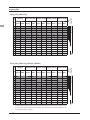
Airplane/glider
Flying wing, Delta wing
2Aileron+1FLAP 2Aileron+2FLAP 2Aileron+4FLAP 4Aileron+2FLAP
Airplane
Glider
Airplane
Glider
Airplane
Glider
Airplane
Glider
1
Aileron
Aileron
Aileron
Aileron
Aileron
Aileron
Aileron
Aileron
Aileron
Aileron
2
VPP
AUX4
VPP
AUX4
VPP
AUX4
Aileron2
Aileron2
Aileron2
Aileron2
3
Throttle
Motor
Throttle
Motor
Throttle
Motor
Rudder
Rudder
Aileron3
Aileron3
4
Rudder
Rudder
Rudder
Rudder
Rudder
Rudder
VPP
AUX4
Aileron4
Aileron4
5
Gear
AUX7
Gear
AUX6
Gear
AUX6
Flap
Flap
Rudder
Rudder
6
Aileron2
Aileron2
Flap
Flap
Flap
Flap
Flap2
Flap2
VPP
AUX4
7
AUX6
AUX6
Aileron2
Aileron2
Aileron2
Aileron2
Flap3
Flap3
Flap
Flap
8
AUX5
AUX5
AUX5
AUX5
Flap2
Flap2
Flap4
Flap4
Flap2
Flap2
9
Elevator
Elevator
Elevator
Elevator
Elevator
Elevator
Elevator
Elevator
Elevator
Elevator
10
Camber
Camber
Camber
Camber
Camber
Camber
Camber
Camber
Camber
Camber
11
AUX1
AUX1
AUX1
Butterfly
AUX1
Butterfly
Gear
Butterfly
Gear
Butterfly
12
AUX1
AUX1
AUX1
AUX1
AUX1
AUX1
Throttle
Motor
Throttle
Motor
DG1
SW
SW
SW
SW
SW
SW
SW
SW
SW
SW
DG2
SW
SW
SW
SW
SW
SW
SW
SW
SW
SW
FASST MULT
Glider
FASSTest 14CH
FASSTest 12CH
S-FHSS
FASST 7CH
Airplane
The output
CH of each
system
RX
CH
2Aileron
Flying wing, Delta wing (Winglet 2 Rudder)
Airplane
Glider
2Aileron+1FLAP 2Aileron+2FLAP 2Aileron+4FLAP 4Aileron+2FLAP
Airplane
Glider
Airplane
Glider
Airplane
Glider
Airplane
Glider
Aileron
Aileron
Aileron
Aileron
Aileron
Aileron
Aileron
Aileron
Aileron
Rudder2
Rudder2
Rudder2
Rudder2
Rudder2
Rudder2
Aileron2
Aileron2
Aileron2
Aileron2
3
Throttle
Motor
Throttle
Motor
Throttle
Motor
Rudder
Rudder
Aileron3
Aileron3
4
Rudder
Rudder
Rudder
Rudder
Rudder
Rudder
Rudder2
Rudder2
Aileron4
Aileron4
5
Gear
AUX7
Gear
AUX6
Gear
AUX6
Flap
Flap
Rudder
Rudder
6
Aileron2
Aileron2
Flap
Flap
Flap
Flap
Flap2
Flap2
Rudder2
Rudder2
7
VPP
AUX6
Aileron2
Aileron2
Aileron2
Aileron2
Flap3
Flap3
Flap
Flap
8
AUX5
AUX5
VPP
AUX5
Flap2
Flap2
Flap4
Flap4
Flap2
Flap2
9
Elevator
Elevator
Elevator
Elevator
Elevator
Elevator
Elevator
Elevator
Elevator
Elevator
10
Camber
Camber
Camber
Camber
Camber
Camber
Camber
Camber
Camber
Camber
11
AUX1
AUX1
AUX1
Butterfly
VPP
Butterfly
Gear
Butterfly
Gear
Butterfly
12
AUX1
AUX1
AUX1
AUX1
AUX1
AUX1
Throttle
Motor
Throttle
Motor
DG1
SW
SW
SW
SW
SW
SW
SW
SW
SW
SW
DG2
SW
SW
SW
SW
SW
SW
SW
SW
SW
SW
* Output channels differ by each system of a table. When using a system with few channels, there
is a wing type which cannot be used. It cannot be used when there is a function required out of
42 <Receiver and Servo Installation>
FASST MULT
Aileron
2
FASSTest 14CH
FASSTest 12CH
S-FHSS
FASST 7CH
1
The output
CH of each
system
RX
CH
2Aileron
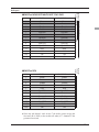
Helicopter
CH
All Other
H-4, H4X Swash
Aileron
Aileron
2
Elevator
Elevator
3
Throttle
Throttle
Rudder
Rudder
5
Gyro/RUD
Gyro/RUD
6
Pitch
Pitch
7
Governor
Governor
8
Needle
Elevator2
9
Gyro2/AIL
Gyro2/AIL
10
Gyro3/ELE
Gyro3/ELE
11
AUX1
AUX1
AUX1
AUX1
SW
SW
DG2
SW
SW
All Other
H-4, H4X Swash
● FASSTest12CH
CH
Aileron
Aileron
2
Elevator
Elevator
3
Throttle
Throttle
4
Rudder
Elevator2
5
Pitch
Pitch
6
Gyro/RUD
Gyro/RUD
7
Governor
Governor
8
Governor 2
Rudder
9
Gyro2/AIL
Gyro2/AIL
10
Gyro3/ELE
Gyro3/ELE
DG1
SW
SW
DG2
SW
SW
FASSTest 12CH
1
The output
CH of each
system
12
DG1
FASST MULT
4
FASSTest 14CH
S-FHSS
FASST 7CH
1
The output
CH of each
system
● FASSTest14CH/FASST MULTI/FASST 7CH/S-FHSS
¦% L ! `5 D #50 0¨$ # $ ` governor is not used.
<Receiver and Servo Installation>
43
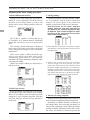
MODEL BASIC SETTING PROCEDURE
Airplane/glider basic setting procedure
1. Model addition and selection
3. Fuselage linkage
Initially, the T14SG assigns the first model to
model-01 in the transmitter. The Model Select
function of the Linkage Menu is used to add
models and to select amongst models which are
already set.
Connect the ailerons, elevators, throttle, rudder,
etc. in accordance with the model's instruction
manual. For a description of the connection
method, see the Receiver and Servos Connection.
The T14SG is capable of storing data for up
to 30 models in its internal memory. Additional
model data can also be saved to an optional SD
card.
The currently selected model name is displayed
j
before changing any settings, always confirm the
model name.
When a new model is added, the Model type
select screen and System mode setup screen
automatically appear. Please be aware that the
transmitter will stop transmitting temporarily when
you change the model.
When a new model is added, you will need to relink the receiver.
Note that even for the same "airplane
model", when the wing type and tail type
are different, the channel assignment may
be different. (The channel assigned to each
function can be checked at the Function
menu of the Linkage Menu.)
<4:
)0
%: $ 4 ! " 3#! , :!#$
4!$ ,
#,
:!$DD
!!!
2. Model type selection
Select the model type matched to the aircraft
with the Model Type select function of the Linkage
Menu. For an airplane, select the model type from
among the 2 types: airplane and glider. And then
select the wing type and the tail type matched to
the aircraft.
44 <Model Basic Setting Procedure>
4. Throttle cut setting (Airplane)
Throttle cut can be performed with one touch by a
switch without changing the throttle trim position.
Set throttle cut with the Throttle Cut function of
the Linkage Menu. After activating the throttle cut
function and selecting the switch, adjust the throttle
position so that the carburetor becomes fully closed.
For safety, the throttle cut function operates the
throttle stick in the 1/3 or less (slow side) position.
The offset amount of the aileron, elevator, and
flap servos can be adjusted as needed. Also the
be adjusted. You can also set the Auto Mode, which
will link Airbrake to a stick, switch, or dial. A
separate stick switch or dial can also be set as the
ON/OFF switch.
5. Idle down setting (Airplane)
The idling speed can be lowered with one touch
by a switch without changing the throttle trim
position. Perform this setting with the Idle Down
function of the Linkage Menu. After activating the
Idle Down function and selecting the switch, adjust
the idle down speed. For safety, the idle down
function acts only when the throttle stick is in the
lowest part of its throw.
*While the Throttle Cut function is in operation, the Idle
Down function does not work.
WE\#",$
The Condition Select function automatically
allocates the normal condition (NORMAL) for
each model. NORMAL is the default condition and
is the only one active when a new model type is
to a description of the CONDITION function.
6. D/R function
D/R function is used to adjust the throw and
operation curve of the stick functions (aileron,
elevator, rudder and throttle) for each switch
#$#$
7
the maximum throw directions in the End Point
settings.
(Airplane)
*The NORMAL is always on, and remains on until other
conditions are activated by switches, stick positions, etc.
Please refer to the section entitled Switch Selection Method
for additional information on how to do so.
*It is possible to customize the activation of the flight
conditions.
*The Condition Delay can be programmed for each channel.
The Condition Delay is used to change the servo throw
smoothly when switching conditions.
(Glider)
7. Airbrake (Airplane)
This function is used when an airbrake is
necessary when taking off or diving, etc. Please
note: this menu item is only available under certain
8
if a single aileron wing type has been selected.
75
be activated by a switch.
<Model Basic Setting Procedure>
45
Helicopter basic setting procedure
This section outlines examples of use of the helicopter functions of the T14SG. Adjust the actual values,
etc. to match the fuselage used.
functions for the chosen model type. Six swash types are
available for helicopters.
*For a description of the swash type selection, refer to the
MODEL TYPE function.
1. Model addition and selection
Initially, the T14SG assigns the first model to
model-01 in the transmitter. To add new models
or to select a model already programmed, use the
Model Select function of the Linkage Menu.
3. Flight condition addition
7nditions
per model.
This is convenient when selecting a model
after entering the model's names in advance. The
T14SG is capable of storing up to 30 models in the
transmitter's internal memory. Additional models
can also be stored in an optional SD card.
The currently selected model is displayed in
the middle of the screen. Before flying and before
changing any settings, always confirm the model
name.
When a new model is added, the Model Type select
screen and system mode setup screen automatically
appear. Change, or check that they match the swash
type and receiver type of the model used.
When a new model is added, you will need to relink the receiver.
The Condition Select function automatically
<
0%)
<+),8
1"73,
<+),8
-"73,
<+),8
'"73
/)+/
Note: Since you may accidentally activate
a condition that not previously setup during
deleting conditions that are not used.
*For a description of the condition deletion, refer to the
Condition Select function.
2. Model type and swash type selection
If a different model type is already selected,
select helicopter with the Model Type function of
the Linkage Menu, and then select the swash type
matched to the helicopter.
The NORMAL condition is always on, and
remains on until other conditions are activated by
switches.
The priority is throttle hold/idle up 3/idle up 2/
idle up 1/normal. Throttle hold has the highest
priority.
The Condition Delay can be programmed for
each channel and condition. The Condition Delay
is used to change the servo throw smoothly when
switching conditions.
,
\#"#
$
!&8D$
8!
<$1&$"73,
84$4!
<$-&$"73,
*The Model Type function automatically selects the
appropriate output channels, control functions, and mixing
8
#&$"73.
8
46 <Model Basic Setting Procedure>
4. Servo Connection
5. Throttle/Pitch curve setting
Connect the throttle rudder, aileron, elevator,
pitch, and other servos in accordance with the
kit instruction manual. For a description of the
connection method, see "Receiver and Servos
Connection".
This function adjusts the throttle or pitch
operation curve in relation to the movement of the
throttle stick for each condition.
Note: The channel assigned to each function
can be checked at the Function menu of the
Linkage Menu.
7"#
Activate the throttle curve of each condition with
the condition select switch.
!:!
< $ 4 ) 0 % %
/31!
! # :
$!
$ $D <$:!
# # ! $44'+4
#:!
*>!$C
C
<
"#
%:$
.
* !
%:$
>" 3#!
, # $ 4
!$ ,
Activate the pitch curve of each condition with
the condition select switch.
!
0$$$5!9º~6º
" $ $ 9C$
*Stability at hovering may be connected to the throttle curve.
Adjustment is easy by using the hovering throttle function
and hovering pitch function together.
<$1
#$1$
! H
"3Eº1-º
<$-
#$$1
#Bº
/
% 4 !5!! $ "$,5$/31!
*If any interactions are noticed, for a description of the
linkage correction function, please refer to the SWASH
function.
?
5!$@
#&3Eº1-º
<Model Basic Setting Procedure>
47
6. D/R function
D/R function is used to adjust the throw and
operation curve of aileron, elevator and rudder for
each condition.
*For throttle and pitch curve settings, refer to the aforementioned "Throttle/Pitch curve setting"
7
_+
the maximum throw directions.
function from the Model Menu, and set the curve
for each condition. (At initial setting, this function
is in the "INH" state. To use it, set it to the "ON"
state.)
#
Activate the mixing curve of each condition with
the condition select switch.
%5!$
8+!5!
8 ! !! $
8+!5<$1
SE,
!"#
The gyro sensitivity and mode switching
function is utilized to adjust the gyro mixing of the
model, and can be set for each condition.
84$4:
8+!5/
# #
$ !Cº
9. Throttle hold setting
!&.
!5!!
< $ 1D< $ -D# & .
!!!
/4 3
$4!
WE"()##
Note: When using a Futaba GY Gyro, or other
heading hold gyro, this Pitch to RUD mixing
should not be used. The reaction torque is
corrected by the gyro. When operating the
gyro in the AVCS mode, the mixed signal will
cause neutral deviation symptoms and the
gyro will not operate normally.
*If throttle hold is necessary, please refer to the THR HOLD
function.
10. Throttle cut setting
Throttle cut provides an easy way to stop the
!
at idle. The action is not functional at high throttle
to avoid accidental dead sticks. The switch’s
location and direction must be chosen, as it defaults
to NULL.
*With throttle stick at idle, adjust the cut position until the
engine consistently shuts off, but throttle linkage is not
binding.
Use this function when you want to suppress
the torque generated by the changes in the pitch
and speed of the main rotor during pitch operation.
Adjust it so that the nose does not swing in the
rudder direction. However, when using a heading
hold gyro like those shown above, do not use Pitch
to rudder mixing.
Activate the Pitch to rudder (Pit -->RUD) mixing
48 <Model Basic Setting Procedure>
**E!
"
pitch interaction
The swash mix function is used to correct the
swash plate in the aileron (Left/Right Cyclic)
and elevator (Forward/Aft Cyclic) direction
corresponding to each operation of each condition.
*ME7"##
*If throttle mixing is necessary for a compensation for
slowing of engine speed caused by swash plate operation
during aileron or elevator operation, please refer to the
THROTTLE MIX function.
*E'"
#
!5
#!5
3 !5
:!% .!5
# !5 !5 <Model Basic Setting Procedure>
49
SYSTEM MENU
The System Menu sets up functions of the
transmitter: This does not set up any model data.
* ! ! "A" !
4
<SensorTouch™>
" ?"A"#,0 0,8@
!
RTN HOME/
EXIT $
"
0
%$
RETURN
"
$ # System Menu functions table
[TRAINER]: Starts and sets the trainer system.
[DISPLAY]: LCD and back-light adjustment
[USER NAME]: User name registration
[SOUND]: Turns off the buzzer.
[H/W SET]: H/W reverse, calibration and stick mode
[START SEL.]: Immediately, a model selection can be performed
[AUTO LOCK]: The automatic lock function of two kinds of touch sensors
[INFO]: Displays the program version, SD card information, product ID, and language selection.
[SBUS SERVO]: S.BUS servo setting.
50 <Functions of System Menu>
#!
TRAINER
T14SG trainer system makes it possible for the
instructor to chose which channels and operation
modes that can be used in the students transmitter.
The function and rate of each channel can be
set, the training method can also be matched to
the student's skill level. Two transmitters must be
connected by an optional Trainer Cord, and the
Instructors’ transmitter should be programmed for
trainer operation, as described below.
When the Instructor activates the trainer switch,
the student has control of the aircraft (if MIX/
FUNC/NORM mode is turned on, the Instructor
can make corrections while the student has control).
When the switch is released the Instructor regains
control. This is very useful if the student gets the
aircraft into an undesirable situation.
"!
" :0<D8*D
0!
% NOTE: This trainer system can be used in the
following manner;
1. With the T14SG transmitter and a conventional
transmitter, if the channel order is different,
it is necessary to match the channel order
before using this function.
You can select the channel of input data
from student's transmitter in the "FUNC" or
"MIX" mode.
2. When the T14SG is used as the instructor’s
transmitter, set the modulation mode of the
student’s transmitter to PPM.
If being used as the student, T14SG can be
connected to the instructor's transmitter which
the PPM mode as the student's modulation
mode is required. T14SG always sends PPM
mode signal from the trainer jack.
3. Be sure that all channels work correctly in
Corresponding types of transmitters and trainer mode settings:
#$!
<
"
#1;".D#1B0 #1;".D#1B0
#1;043;C4
#1;".
#1-4#1-.4
3'C
#1;".
#1;".
#1;".
#1;".
#1;043;C4
#1-4#1-.4
3'C
#B.43-C
#1C*4#1C*.4
#G*4#E*4
#E*4#B
<6!
"!#$
#
0!
*/!
#*
1;*/D1F*/
% 1;*/D1F*/
-
% 1-*/
*03.'
-;.
1-*/
0
% 1-*/
B*/
%""#30)#%""#308)#
-
-
% B*/
0
-
-
#1-.8#0;;C9
% % B*/
B*/
% % -
-
#1-.8#0;;C9
#1;".
% 1-*/
% 1-*/
-
#1;".
% 1-*/
% 1-*/
-
#1;".
% -
% B*/
-
#B.43-C
#1C*4#G*4
#E*4#F,4
#;,
#1C*.4#E*
#B4#F
% "6!
"!#$
#
0!
*/!
0!
#1-.8#0;;C9
G*8#0;;19
#*
#1-.8#0;;C9
G*8#0;;19
#*
<Functions of System Menu>
51
"?#%<,@"!!
$ #
<SensorTouch™>
"
0
"!
%:
"!
"!
! R T N H O M E / E X I T $
#5$
RETURN
Mode and switch selection
1% $ $ ; "1 !
Note: The trainer function won’t be turned
on unless the Instructor's transmitter receives
signals from the student's transmitter. Be
sure to confirm this after connecting your
trainer cable.
Operating mode selection
"$$13'
-0 ?%*#@ ?1-DB*/@
! # $!
'" ! # $ # #
! # !
!4"1 2%*#2&, $ ?@
?@
21-DB*/2&7#1;".4
#1;04 #1-4 #1-. 3;C4 ?1-*/@
?B*/@
<&
;0?"7@!
# $
"2"!2
!!
2"72&"
<&"/
*The switch mode can also be selected when setting the ON
position on the switch setup screen. When [ALTERNATE
OFF] is selected, normal ON/OFF operation is performed.
When [ALTERNATE ON] is selected, the trainer function
is alternately turned on and off each time the switch is
operated. This allows alternate ON/OFF switching even
when a momentary switch (SH) is used.
52 <Functions of System Menu>
10 ?0+,@ ! # $!
-" ! # $ # #
! # !
!4"1 20+,2&"$!
NORM: The model is controlled by signals from the student
transmitter.
MIX mode: The model is controlled by signals from the
instructor and student transmitters. (Reset the student's
model data to the default condition.)
FUNC mode (function mode): The model is controlled by
signals from the student transmitter with the instructor 's
setting. (Reset the student's model data to the default
condition.)
OFF: Only the instructor side operates.
Adjusting the student's rate.
*This can be adjusted for students who may need lower rates
than a more experienced student.
10 ?%#,@ ! # $!
-%: 2%#,2&%:
"&C1CC
<&1CC
*When you want to reset the value to the initial state, touch
the RTN button for one second.
'# :!4 # !
Changing the student's channel
*The setting above allows setting of the channel assignment
of student side when [MIX] or [FUNC] was selected.
10?"#8*/@!
# $!
-" # $ # #
#!
!4"1 2"#8 */2& 0 <6 6 ! #
$ ! !40
$ $ # ! 0 $
!
<Functions of System Menu>
53
DISPLAY
)*+ 3:!4!
LCD contrast, back-light brightness and backlight off-timer adjustment are possible:
Moreover, a display unit can be chosen from the
metric system or yard/pound.
"?+<"
)%A@!!
$ # <SensorTouch™>
"
0
%:
"!
"!
! R T N . H O M E / E X I T $
RETURN
LCD contrast adjustment
1"2*#%"#2# $!:
2*#%"#2& %: $
"&)C19+
<&9
*When you want to reset the value to the initial state, touch
the RTN button for one second.
-## :!
!
Back-light brightness adjustment
1" 2<./#,""2 #
$!
: 3 2<./#,""2& %: $
"&41-C)
<&1C
*When you want to reset the value to the initial state, touch
the RTN button for one second.
54 <Functions of System Menu>
-## :!
!
Back-light off-timer
1"2#<0,2# $!:
33! 2#<0,2&%:! 3
$ " & 1C -;C 1C 4
<&1C
*When you want to reset the value to the initial state, touch
the RTN button for one second.
-## :!
!
Unit system adjustment
1" 28<# "A"2 # $!:
"&0,#<*A%+D
8+
-## :!
!
USER NAME
8!
This function allows the modelers to change the
T14SG user name.
*A name of up to 10 characters can be entered as the user
name. Please note that a space is also counted as one
character.
" ?8", %0,@ "! ! $ # 8!
<SensorTouch™>
"!
"!
! R T N HOME/EXIT
$
"
0
RETURN
User name registration
*1D'
1*! &
?0!@
"?}@?~@4# ?+@
7?+,),#,@# 4!!
?%@
7 ! # 4
$
!!
*-D'
*'D'
*A name of up to 10 characters long can be entered as the
user name. (A space is also counted as 1 character.)
- 8$ !$ $4 ?,#,@
# # !
$ 4 ?*%*,)@# <Functions of System Menu>
55
SOUND
#
The warning sound and other sounds of the
T14SG transmitter can be turned off.
*When “WARNING” was set to OFF, the no operation alarm
(30 minutes), mixing warning sound, and low battery alarm
sounds also turned off.
" ?"8+@ ! ! $ # <SensorTouch™>
"!
"!
! R T N . H O M E / E X I T $
RETURN
On/off operation
10 ?#<0,@?7%<.@
?#/, "8+@ ! #
$!
-" *The display blinks.
'## 56 <Functions of System Menu>
"
0
"!
H/W SETTING
/!
H/W reverse
This function reverses the operation direction of
the sticks, switches, trimmer levers, and knobs.
Note: This setting reverses the actual operation
signal, but does not change the display
indicators. Use the Normal mode as long as
there is no special reason to use the Reverse
mode.
Note: This will not change the throttle ratchet,
etc. Those are mechanical changes that
must be performed by a Futaba service
center.
Note: After changing the mode, these changes
are only applied to new models. It is not
applied to an existing model.
Stick calibration
J1-J4 stick correction can be performed.
Stick mode
This function changes the stick mode of
transmitter.
"?/D7",#@!!
$ # <SensorTouch™>
"
0
"!
"!
! R T N H O M E / E X I T $
%$
RETURN
Operation direction reversal method
Changing stick mode
1"?/D7,,",@$
#
1" ?"#<*I 0+,@ $
#
-0 ! $
/D7 # $!
' " ! # $ 7 #
4$
# ! ! 4
"1 202&!$
2,2&$
- 0 2"#<*I 0+,2 !
# $!
' " ! # $ 7
# 4!
# ! ! 4
"1 (J3)
(J2)
(J4)
0
1
'
;
1
%
%
#
,
#
,
(J1)
'
,
#
,
#
;
%
%
<Functions of System Menu>
57
Stick calibration method
*J3 and J4 correction is described below. J1 and J2
corrections are performed using the same procedure.
1" ?*%)<%#<@ $
#
-0 '3; # '0';$
$# ;" ' ; !
9"';$
F # ! $ $ $ $!!
58 <Functions of System Menu>
START SEL.
<!!4! $!
START SEL is a function which starts and can
perform a model selection immediately.
Each time, it is convenient for the modeler
which is enjoying two or more models by one of a
transmitter.
turned ON. With a few quick touches, it is possible
to change models whereas before it would require
a multi-step process. The T14SG stores up to four
models in the Quick Select offerings.
Quick Select Screen
When the transmitter is turned on, it will open to
the Model Selection Screen immediately.
As the name suggests, the Quick Model Select
Function enables the modeler to change the
selected models rapidly each time the transmitter is
Model Select Screen
<SensorTouch™>
"!
"!
! R T N HOME/EXIT
$
RETURN
Setting Up and Adjusting the Quick Select Models
1# " " "#%# ",) ! #1;". "! 0
# ! $ "A" "! ! 8 "#""
"#%# ",) $ #
>!
-# " " "#%# ",) ! $
! "
0 " $$ #
" 0 "4
"# ! 7 4 $ # "#
!$7
"8<*I",)4$
# !
activated, there are two additional options available
for customization; ALWAYS and MDL (Model).
These options determine if/when the Quick Select
information will appear on-screen. ALWAYS,
as the name suggests, indicates that each time
the transmitter is powered-up, the Quick Select
information will appear on-screen. The MDL
(Model) setting indicates that the Quick Select
information will appear on-screen only when
the MDL button is pressed simultaneously as the
transmitter is turned ON. With the Quick Select
mode highlighted, use the SensorTouch to move to
the activation setting options. Model (MDL) is the
default setting. Press the Return (RTN) button to
bring forth the options, then scroll to the ALWAYS
setting using the SensorTouch pad. Press the Return
#\7E$Y
Quick Select Activation:
With the Quick Select (QUICK SEL.) option
<Functions of System Menu>
59
Model Select Screen
Assigning models to the sensor buttons:
There are four sensors/buttons that correspond This allows the Model Select screen to be accessed
with the SensorTouch: Link (LNK), Model (MDL) immediately upon turning ON the transmitter.
System (SYS) and S1. As such, it is possible to offer
* Please note: this function cannot be utilized at the same time
as the Quick Select function. If more than four models are
up to four models available through the Quick Select
[%
<
utilized as it will save time when selecting the desired aircraft.
most often.
"!%
would be the best choice.
18 "#4 * Please note: the Model Select function does not allow access
D >!(5!$4
to the RENAME, COPY or DELETE options. To utilize one
))I
of these options, please access the Model Select screen in
-7 $ 5 the typical manner as described in the complete instruction
4$# manual.
!
1#
" " "#%# ",) ! '8 "#4 #1;". "! 0
! # # ! $ !4$# "A" "! ! 8 ;$!
"#""
"#%# ",) $ #
>!
Using the sensors to select the model:
1# !4 " < 0 0+) 4 $ $ 0 0+) $ $ !
-# " " "#%# ",) ! $
! "
0 " $$ #
"0"4
"#
!7
4$# "# 0 " 0+,) ",) # 0"
* Please note: Even if the Quick Select function is active, the
Power Mode screen will appear when the transmitter is turned
ON while simultaneously pressing the Return (RTN) button.
- # ! $
4 3 5!$40+,)3C'"14 3
Model Select Activation:
"1 40 With the Model Select (MODEL SEL.) option
3C' # #1;". activated, there are two additional options available
>!!!!
for customization; ALWAYS and MDL (Model).
* If the Return (RTN) button is double-clicked, the T14SG the
current model is selected as indicated on the display. That is,
the model that was used prior to the last time the transmitter
was turned OFF.
60 <Functions of System Menu>
These options determine if/when the Model Select
information will appear on-screen. ALWAYS,
as the name suggests, indicates that each time
the transmitter is powered-up, the Model Select
information will appear on-screen. The MDL
(Model) setting indicates that the Model Select
information will appear on-screen only when
the MDL button is pressed simultaneously as the
transmitter is turned ON.
With the Model Select mode highlighted, use the
SensorTouch to move to the activation setting
options. Model (MDL) is the default setting. Press
the Return (RTN) button to bring forth the options,
then scroll to the ALWAYS setting using the
SensorTouch pad. Press the Return (RTN) button
Y
Using the Model Select Function:
1# !4 0 " < 0 0+) 4 $ $ 0 0+) $ $ !
*Please note: Even if the Model Select function is active, the
Power Mode screen will appear when the transmitter is turned
ON while simultaneously pressing the Return (RTN) button.
-# "# !
3 ! # !
! !<!
4"#
$( %4 !4
$ # # #1;". >!!!!
<Functions of System Menu>
61
AUTO LOCK
#!"#
The Auto Lock function makes it possible to lock
the transmitter to prevent any unwanted input from
The auto lock function can be set in two ways.
LOCK TIMER
Auto Lock functions automatically when there is
no operation from the HOME screen display for a
chosen number of seconds.
● Manual lock
START LOCK
Auto Lock functions automatically when the
model changes or power is turned on.
*To temporarily allow access to the T14SG programming
press and hold the S1 or HOME/EXIT bitton for one second.
Please note, the Auto Lock function timer will resume
immediately once again.
If HOME/EXIT button is touched 1
second or more from a HOME screen,
a SensorTouch locks manually.
● Manual lock
If S1 button is touched 1 second
or more from a HOME screen, a
SensorTouch locks manually.
<SensorTouch™>
"!
"!
! R T N . H O M E / E X I T $
RETURN
Auto lock method
1$ % !
!
● Lock release
Every lock function's touch [ 1 second
or more ] of S1 button will release the
lock.
● Lock release
Every lock function's touch [ 1 second
or more ] of HOME/EXIT button will
release the lock.
- %: ! %
) # ! !! /0, # ! : ! $ 'C < !
4$$ ● Display of a lock
If locked, there will be sound and the
icon of a key will come out.
' # " ) 4 4
! #1;". !$$#
!64$
"1
Danger
*If neither the Lock Timer or Start Lock functions are active
(OFF), then the key lock remains even if the power is turned off.
*If the Lock Timer is enabled and the Start Lock is off, the key
lock status is canceled each time the T14SG is turned on.
62 <Functions of System Menu>
It is recommended to Lock the
%7
any accidental touches which could
change settings and cause an accident.
+$$!4"+!4$<+
INFO
The T14SG system program version information,
SD card information (current and maximum
$
ID are displayed on the Information screen.
The language displayed in home, menu, and
setup screen is selectable.
*When the SD card is not inserted, the SD card information is
not displayed.
"?<@!!
$ #
<SensorTouch™>
"
0
"!
"!
"!
! R T N HOME/EXIT
$
RETURN
Information
Language selection
2
+8*#2&
<+! 2<+2&<+! 2)%.8%.,2&##1;".
2,"<2& #1;". ! $! !
2%,%2&%#1;".
2*%+ "<,2& *D05!! ! !>"+
10 2)%.8%.,2 !
# $!
-* # $ 7 #
4
#!4,+<#
$"1 <Functions of System Menu>
63
SBUS SERVO
"8"
An S.BUS servo can memorize the channel
and various settings you input. Servo setting
can be performed on the T14SG screen by
wiring the servo as shown in the figure.
'3 A3
#1;".
" ?"8+@ ! ! $ # "!
"!
! R T N . H O M E / E X I T $
"8"D"8"-
"
<SensorTouch™>
"
0
"!
RETURN
Servo ID number
Individual ID numbers are memorized for your
S.BUS(2) servos in your T14SG. When a servo is
used, the servo ID number is automatically read by
the transmitter. If you use multiple S.BUS(2) servos
and do not want to change the settings on all that are
mounted in a fuselage, only the desired servo in the
' servo.
* After reading completion, with connection of the above
!
can be operated and carried out.
* S9070SB cannot be arranged by T14SG.
* With some S.BUS(2) servos, there are some functions with
cannot be used. If a function cannot be used, the display screen
will change.
(Only the function which can be used by a servo is displayed.)
Procedure for changing S.BUS servo setting
1"?"8"",@"!0
-7> '
?,*%))@$'"1$
# <+ $ ?,*%))@ ⇒ # $ ⇒ #$1
;7!$
?</@<+! ?%*#@ <+ 9"!
5$
F ? 7 < # , @ $ ' ? 7 < # , @ ⇒ #$ ⇒ #$1
#
64 <Functions of System Menu>
?<<#@4 $ ?<<#@ ⇒ # $ ⇒ #$1
S.BUS Servo Description of function of each parameter
*There are a function which can be used according to the kind of servo, and an impossible function.
Displays the ID of the servo whose parameters are to be read. It cannot be changed.
Channel of the S.BUS system assigned to the servo. Always assign a channel before use.
The direction in which the servo rotates can be changed.
When “Retractable” is selected and the servo has been continuously stopped for 30 seconds, the dead band
expands and unnecessary hold current due to external force is eliminated. When a new control signal enters,
normal operation is resumed. When using the servo as a landing gear servo, select “Retractable”. Also adjust the
servo travel to match the landing gear movement range.
Restricts operation in the specified direction the instant the power is turned on. By using this setting, the first initial
movement when the power is turned on slowly moves the servo to the specified position.
The state of the servo when the servo input signal is lost can be specified. The "Hold" mode setting holds the
servo in its last commanded position even if using AM or FM system.
This function changes smoothness of the servo operation relative to stick movement changes. Smooth setting is
used for normal flight. Select the "OFF" mode when quick operation is necessary such as 3D.
The neutral position can be changed. When the neutral offset is large value, the servo's range of travel is restricted
on one side.
Speeds can be matched by specifying the operating speed. The speed of multiple servos can be matched without
being affected by motor fluctuations. This is effective for load torques below the maximum torque.
However, note that the maximum speed will not be exceed what the servo is capable of even if the servos
operating voltage is increased.
The dead band angle at stopping can be specified.
[Relationship between dead band set value and servo operation]
Small ° Dead band angle is small and the servo is immediately operated by a small signal change.
Large ° Dead band angle is large and the servo does not operate at small signal changes.
(Note) If the dead band angle is too small, the servo will operate continuously and the current consumption will
increase and the life of the servo will be shortened.
!
The left and right travels centered about the neutral position can be set independently.
"
The minimum current applied to the internal motor when starting the servo can be set. Since a small travel does
not start the motor, it essentially feels like the dead band was expanded. The motor can be immediately started by
adjusting the minimum current which can start the motor.
[Relationship between boost set value and servo operation]
Small ° Motor reacts to a minute current and operation becomes smooth.
Large ° Initial response improves and output torque increases. However, if the torque is too large, operation will
become rough.
<Functions of System Menu>
65
"#$$
OFF : It is the boost ON at the time of low-speed operation.(In the case of usual)
ON : It is always the boost ON.(When quick operation is hope)
The characteristic when the servo is stopped can be set.
When smaller than the standard value, the characteristic becomes an overshoot characteristic. If the value is
larger than the standard value, the brake is applied before the stop position.
Especially, when a large load is applied, overshoot, etc. are suppressed by inertia and hunting may occur,
depending on the conditions. If hunting (phenomena which cause the servo to oscillate) occurs even though the
Dead Band, Stretcher, Boost and other parameters are suitable, adjust this parameter to a value larger than the
initial value.
[Relationship between damper set value and servo operation]
Small ° When you want to overshoot. Set so that hunting does not occur.
Large ° When you want to operate so that braking is not applied. However, it will feel like the servo response has
worsened.
(Note) If used in the hunting state, not only will the current consumption increase, but the life of the servo will also
be shortened.
%
The servo hold characteristic can be set. The torque which attempts to return the servo to the target position
when the current servo position has deviated from the target position can be adjusted.
This is used when stopping hunting, etc., but the holding characteristic changes as shown below.
[Relationship between stretcher and servo operation]
Small ° Servo holding force becomes weaker.
Large ° Servo holding force becomes stronger.
(Note) When this parameter is large, the current consumption increases.
"&&
When the power supply of a servo is previously turned on at the time of a power supply injection without taking
transmit of a transmitter, the buzzer sound of about 2.5 Hz continues sounding from a servo.
(Even when the transmit of a transmitter is taken out previously, a buzzer becomes until the signal of a servo is
outputted normally, but it is not unusual.)
The transmitter has been turned OFF ahead of a servo power supply → The buzzer sound of about 1.25 Hz
continues sounding as servo power supply end failure alarm.
(Do not insert or remove the servo connector while the receiver power is ON. A buzzer may sound
by incorrect recognition.)
* Buzzer sound is generated by vibrating the motor of a servo.
Since current is consumed and a servo generates heat, please do not operate the number more than needed or
do not continue sounding a buzzer for a long time.
66 <Functions of System Menu>
FUNCTIONS OF LINKAGE MENU
The Linkage Menu is made up of functions
which perform model addition, model type
selection, system type, end point setting, and other
model basic settings.
The functions which can be selected depend on
the model type. A typical menu screen is shown
below.
% ) ! $$)I !
<SensorTouch™>
"!
)
! RTN HOME/
EXIT $
"
0
*$
RETURN
**The display screen is an example. The
screen depends on the model type.
"
$ # Linkage Menu functions table
[SERVO]: Displays the servo test and operation position
[MODEL SEL]: Model addition, call, deletion, copy, model name setting
[MODEL TYPE]: Model type, wing type, swash type, etc. selection
[SYSTEM]: System mode selection, link of a transmitter and receiver, area mode selection
[FUNCTION]: Channel assignment of each function can be changed
[SUB-TRIM]: Adjusts the neutral position of each servo
[REVERSE]: Reverses the servo travel direction
[FAIL SAFE]: Fail safe function and battery fail safe function setting
[END POINT]: Servo travel adjustment and limit setting
[SERVO SPEED]: Speed setup of a servo
[THR CUT]: Stops the engine safely and easily (airplane and helicopter only)
[IDLE DOWN]: Lowers the idle speed of the engine (airplane only)
¤%<%\E3¥)J8#
$
[SWASH]: Swash AFR and linkage correction function (helicopter only)
[T1-T4 SET.]: Control step amount and mode selection of the digital trim
[WARNING]: Mixing warning normal reset
[TELEMETRY]: Displays various data sent from the receiver.
[SENSOR]: Various telemetry sensors setting
[DATA RESET]: Model memory set data reset
<Functions of Linkage Menu>
67
SERVO MONITOR
"#¡.$+$D+$$
This is used for testing servo movement.
“Moving Test” (repetition mode) and “Neutral
7#8$
The “Neutral Test” is good for finding the
neutral position of a servo horn.
In order to prevent any potential difficulties,
the servo test function will be inoperable, or
%
the Servo Test function is not operational if the
Throttle Cut is ON in either airplane or helicopter
modes; or if the Throttle Hold is ON in Helicopter
mode.
% ?80,8D0@ $ ! !
" ?",@ ) ! $ # <SensorTouch™>
"!
)
! R T N H O M E / E X I T $
RETURN
Servo test operation
10?@!
# $
!
" ! # #$
# # ! # ! ! 4 "1 ?0<.@&0$$
?,8#%)@& 0 $
- 0 ? 0 < . @ ?,8#%)@!# $!
"?@ # #$$
68 <Functions of Linkage Menu>
"
0
"!
MODEL SELECT
#0"$!!44
4$4!!
This function is used to load the settings of the
desired model into the T14SG’s memory.
The settings may be selected from either the
transmitter’s internal memory or an SD card.
Remember that up to 30 model memories are available
in the transmitter.
The name of the model stored in the transmitter and
the SD card may be changed. This can be very useful
to tell different models settings apart. Each model name
can be as long as 10 characters, and the model name
always appears in the display screen.
The Copy function is used to copy parameters,
settings, etc. from one model data into a second
memory. It may be used for getting a head-start on
setting up models with almost the same settings (only
complete model from scratch). Also, this function may
be used to make a backup copy of a model setup before
any changes are made.
*T14SG can use the model data of T8FGS for SD card,
copying it. However, the model data of T14SG cannot be
used by T8SG (S).
" ?0+,) ",),*#@ ) !
$ # *!
<SensorTouch™>
"
0
"!
"!
)
! RTN H O M E / E X I T $
RETURN
*The display screen is an example. The
screen depends on the model type.
0
Model selection
*Model data saved on the transmitter memory other than the
model currently used can be selected.
1 0 $ 2#2 2*%+2 #
$!
" # ?#@&#!!!
?*%+@&"+
-%!!
!4# '0?",),*#@
;# # % !
!$## !$
Model addition
*A new model can be added to the transmitter memory. It can
not be added to the SD card.
10?,7@
-# # % !
!$$## *The model type setup screen and frequency setup screen are
&
and SYSTEM mode.
*Transmission stops and then starts in the new model.
*The added model appears in the model list of the model
select setup screen.
*Link is required when a new model is
made from a model selection.
*Transmission stops and then starts in the new model.
<Functions of Linkage Menu>
69
Model deletion
*The model stored in the transmitter memory or an SD card
can be deleted.
*The current model can not be deleted.
1 0 $ 2#2 2*%+2 #
$!
" # ?#@&#!!!
?*%+@&"+
- 0 ! ! # '0?+,),#,@
;## 7>!
! $ # 4 ! Model name change
*The model name of the model stored in the transmitter
memory or a SD card can be changed.
1<&
0 $ 2#2 2*%+2 #
$!
" # ?#@&#!!!
?*%+@&"+
- 0 ! !
# '0?,%0,@
;## *The model name setup screen is displayed.
User name (candidate)
?%@
7 ! # 4
$
!!
*A name of up to 10 characters long can be entered as the
model name. (A space is also counted as one character.)
F%! $4
?,#,@ # #!$
4 ?*%*,)@ #
Model copy
*A copy can be made of the model stored in the transmitter
memory or an SD card.
1<&
0 $ 2#2 2*%+2 #
$!
" # ?#@&#!!!
?*%+@&"+
-" ! $ !# '0?*
A@
;## *The copy screen appears.
9< $ ! !!!&
0?%++3)<"#@# $!
"! # ?%++3)<"#@&!
?!!@&$!
*The model stored in the SD card can be replaced.
9 * ! ! &
?0!@
"?}@?~@4# ?+@
7?+,),#,@# 4!!
70 <Functions of Linkage Menu>
<&
0 $ $ 2#2 2*%+2 #
$!
" # F0?*
A@
E## 7>!
! $ # 4!
$
MODEL TYPE
#!$!!$4$4
Six swash types are available for helicopters.
Six types of main wings and three types of tail
wings are available for airplanes and gliders.
Functions and mixing functions necessary for each
model type are set in advance at the factory.
Note: The Model Type function automatically
selects the appropriate output channels,
control functions, and mixing functions for the
chosen model type.
When the Model Type selection command
is accessed, all of the data in the active
memory is cleared (except the following
swash type.) Be sure that you don’t mind
losing this data, or back it up to another
memory using the copying functions.
When changing the helicopter swash type
within the following groups, you can leave
the settings other than the SWASH function.
However, this is initialized when you change
the swash type to the other swash type
group.
Swash type group A:
/314/3'4/'4/,'
Swash type group B:
/3;4/3;
" ?0+,) #A
,@ ) ! $ # <SensorTouch™>
"
0
"!
"!
)
! RTN H O M E / E X I T $
RETURN
(The display screen is an example. The
screen depends on the model type.)
Model type selection
1 0 ! # $!
" $ # %
! ! $$ # # 0?A,"@## #!$
4"1 ?@
# 2#A
,2&0$
27<.2$D&7$
2#%<)2$D&#$
2"7%"/2$&"$
- < $$&
(Helicopter)
0?@#
$!
" ?@ # % !
!$$## % $ # $!
*The wing types which can be selected depend on the mode;
FASST, Multi-ch, or 7ch, etc.
<Functions of Linkage Menu>
71
Model type selection (Airplane, Glider)
Q#F
$
Q#7
!#$
(
7
Model type selection (Helicopter)
!
"
72 <Functions of Linkage Menu>
SYSTEM
"!!4
System Type selection
The T14SG is for 2.4GHz only. The system
can be changed from among 5 choices: FASSTest
1 4 C H , FA S S Te s t 1 2 C H , FA S S T M U LT I ,
FASST 7CH, S-FHSS. It is FASSTest14CH and
FASSTest12CH which can be chosen by R7008SB
set. The method of selection is to the next page.
*If you change the System Type, other model data is not
reset.
*If a system type is changed in Helicopter mode, the
transmitter will offer two selections:
[Yes] : Selection sets the channel order suitable for System
Type. (We recommend here. )
[No] : The present channel order is maintained.
*After any change, remember to test the model and should
fully check servo direction and a motion.
*Analog servos cannot be used with the R7008SB in the
FASSTest 12CH mode.
Dual receiver function (only FASSTest 14CH
mode)
Dual receivers can be linked with the T14SG.
Two receivers are recognized individually by ID
numbers. For example, in R7008SB, CH output
setting function is used, by setting the first as as
"1-8CH", and setting the second as "9-14CH", two
sets of receivers can be used as a set in the model,
allowing you 14 channels. If a Dual receiver
function is used, the following function can set up
individually.
・Battery fail-safe voltage setup
・Telemetry function ON/OFF
・Sensor setup
"?"A"#,0@)!
$ # <SensorTouch™>
"!
)
! R T N H O M E / E X I T $
"
0
"!
RETURN
Area mode selection (Frequency range)
The T14SG transmitter has been designed to
function in many countries. If you will be utilizing
this transmitter in a country other than France,
please make sure that [AREA] is set to "G". If,
however, this transmitter will be utilized in France,
it must be set to "F" in order to comply with French
regulations.FASST mode selection
Receiver linking
The receiver will only be controlled (without
being affected by other transmitters) by the
transmitter it is linked to. When using a receiver
other than one purchased as a set, linking is
necessary.
Moreover, a re-link is required when a new
model is added by model selection, and the time of
system type change.
Linking method
P.37
Cases when linking is necessary:
・7
・7 !! ! %""#1;*/ ↔ %""#1-*/)
・7 ! !
Battery fail-safe voltage setup (only FASSTest
mode)
The voltage which battery fail-safe activates,
can be set when you link. (3.5-8.4V) The receiver
memorizes the setting as it was at link.
Suggested setting voltages are as follows.
0E&E[#E)0L$±@L
DJ#E)KK$±KBKD
DJ+#E)`0$±`D`0
It is a rough reference value.
Since it changes with servos carried in the
condition and the model of a battery, please set to
your own model in a battery consumption current.
<Functions of Linkage Menu>
73
Telemetry function (FASSTest mode only)
To use the telemetry function, set “Telemetry”
to “ACT”.
DL Interval (FASSTest mode only)
When a telemetry function is enabled, the
receiving interval (down-link interval) of sensor
data can be changed.
If a DL interval is increased, the response of
the sensor data display becomes slower, but stick
response will improve.
System Type selection procedure
10 ?%""#31;*/@
!# $!
'## :!
!
Area mode selection (Frequency range)
procedure
10 ?.@ ! # $
!
-" ?.@?@ *"F" is chosen only when using the transmitter is used in
France. Leave this in "G" otherwise.
'## :!
!
Telemetry ACT/INH procedure
-" ! $ ?%""#31;*/@?%""#31-*/@?%""#3
08)#@?%""#3E*/@?"3/""@
10#,),0,#A?%*#@!
# $!
*An example of selections for each system is on the
following page.
'# # :!
!
Dual receiver function (only FASSTest 14CH
mode) procedure
10 ?"<.),@ ! # $!
-"?%*#@?</@ '## :!
!
DL Interval set procedure
10 #,),0,#A +)?1C@
! # $!
-" ?"<.),@ ?+8%)@ <+ !
$
<+"
$
<+8%)4$!$
54
74 <Functions of Linkage Menu>
-" +) ! < +) 4 $$ !
4 $!$
<&1C
%:!&C1-C
'## :!
!
The example for choosing System Type
-Response speed has
priority over number
of channels
-Want to use a
previously used
receiver as is
-Want to use a
miniature receiver
for indoor planes
-Want to use an
S-FHSS system
miniature receiver
-Telemetry requires
only the current
receiver battery
FASST 7CH
-Want to use more channels
-Want to use a large number
of telemetry functions
FASST MULTI
FASSTest 12CH
FASSTest 14CH
R7008SB
R7003SB
R7008SB
R7003SB
R608FS
R6008HS
R6108SB
R6208SB
R6014HS
R6014FS
R6203SB
R6203SBE
R6202SBW
R6303SB
R6303SBE
R617FS
R6004FF
R616FFM
R6106HF
R6106HFC
R6203SB
R6203SBE
R6202SBW
R6303SB
R6303SBE
S-FHSS
R2006GS
R2106GF
R2008SB
(Usable receivers)
(The time of December, 2012)
System Type
■ FASSTest 14CH --- FASSTest system receiver mode. Applicable with the telemetry sensor unit. Up to
18 channels (linear 12+ON/OFF2) can be used.
■ FASSTest 12CH --- FASSTest system receiver mode. Applicable with receiver voltage display. Up to 12
channels (linear10+ON/OFF2) can be used. Telemetry Sensor cannot be used, but
the response speed is a faster than that of the 14CH mode.
s!NALOGSERVOSCANNOTBEUSEDWITHTHE23"INTHE&!334EST#(MODE
■ FASST MULTI
--- FASST-MULTI system receiver mode. Up to 14 channels (linear 12+ON/OFF2) can
be used.
■ FASST 7CH
--- FASST-7CH system receiver mode. Up to 7 channels can be used.
■ S-FHSS
--- S-FHSS system receiver mode. Up to 8 channels can be used.
<Functions of Linkage Menu>
75
FUNCTION
*! When you select model and wing (swash) types,
you will find that the optimized combinations of
servo output channels and functions have been
already preset. If you would like, you can freely
change combinations of servo output channels,
functions (aileron, elevator, etc), and control (sticks,
switches, and trim levers).
*You can also assign the same function to multiple servo
output channels such as assigning elevator function to CH2
and CH3.
Channel Replacement
When the channel is replaced in the Function
menu, replaced channel uses the setting data (ATV,
SUB-TRIM, REVERSE, F/S, and B-F/S, etc.).
Servo Output Channels
For FASSTest 14CH mode, you can set 12 linear
channels and two digital channels. For FASSTest
12CH mode, you can set 10 linear channels and
two digital channels. For FASST MULT mode, you
can set 12 linear channels and two digital channels.
For FASST 7CH mode, you can set only 7 linear
channels. For S-FHSS mode, you can set only 8
linear channels.
*DG1/2 (digital channels)
These channels can function as switched channels. You can
freely change combinations between servo output channels
and input controls (sticks, switches, and trim levers).
Motor Function
If you have either a Glider or Airplane Model
Type selected, and choose to activate the Motor
function, a reverse setting screen is displayed.
*If YES is selected, the output is reversed. If NO is selected,
the output is normal.
Q
#
As a safety precaution to prevent the motor
from starting unexpectedly, please switch
off the motor accordingly. We also suggest
removing the propeller from the motor as an
additional precaution.
" ?8*#<@ ) ! $ # #!$!
2*02&*! !
2",
%2&"$!
<$ T1-T4 SET)<I%.,0,8
<SensorTouch™>
"
0
"!
%:
"!
)
! R T N H O M E / E X I T $
#5$
RETURN
(The display screen is an example. The
screen depends on the model type.)
Function change
Operation control change
10!
# 1 0 2*#)2 ! # *The function selection screen is displayed.
*The control selection screen is displayed.
- 0 ! # *The function name blinks.
' # # 5 7 $4"1 *Multiple channels can be assigned to one function.
-0
4# *The same control can be assigned to multiple channels.
76 <Functions of Linkage Menu>
2
@@%\##$
&6[6j
each condition.
*! 4 0 $D
$! $ 2.2&.$!!
2"2&"
## !
#!$
4"1 ?0@&!!!!$
!$
? % # ) @ & % # ) $ ! 0 5 ! !
3 $4
! ! < $ *[NORMAL]/[REVERSE] selection is possible in "ATL"
mode.
Throttle trim (helicopter only)
Trim setting
0 2#<02 ! # *The trim setup screen is displayed.
# ! !
$&
* The throttle trim in conditions other than "Normal"
condition can be inhibited.
7 ! 4!!
$#
1
*When "X" is displayed, THR trim is inhibited in conditions
other than normal condition.
Trim selection
Channel replacement
0 !4 4 # 0¢
$ # $!
"¢ % ! !
$$ # # $
# ! $ 4"1 *The setting can be changed.
Trim rate setting
0 ?%#,@ ! # $!
"! <&'C
%:!&319C19C
(When the RTN button is touched for one second, the trim
rate is reset to the initial value.)
## :!
!
Trim mode selection
0 ?0+,@ ! # $!
" ! ! % ! ! $$
<Functions of Linkage Menu>
77
SUB-TRIM
"$
The Sub-Trim function is used to set the servo
neutral position, and may be used to make fine
adjustments to the control surface after linkages
and pushrods are hooked up. When you begin to set
up a model, be sure that the digital trims are set to
their center position.
"?"83#<0@)!
$ # <SensorTouch™>
"!
)
! R T N H O M E / E X I T $
"
0
%:
RETURN
(The display screen is an example. The
screen depends on the model type.)
Sub-trim adjustment
10
:# $!
-%: <&C
%:!&3-;C-;C$
(When the RTN button is touched for one second, sub-trim is
reset to the initial value.)
*Before sub-trim adjustment, it is very important to adjust the
linkages at the control surface so that you do not use subtrim, except for very minute adjustments.
'## :!
!
;$$
78 <Functions of Linkage Menu>
REVERSE
8
Servo Reverse changes the direction of an
individual servo’s response to a control input.
For CCPM helicopters, be sure to read the
section on Swash AFR before reversing any servos.
With CCPM helicopters, always complete your
servo reversing prior to any other programming.
If you use pre-built Airplane/Sailplane functions
that control multiple servos, it may be confusing
to tell whether the servo needs to be reversed or a
setting in the function needs to be reversed. See the
instructions for each specialized function for further
details. Always check servo direction prior to every
model memory, hook ups, and radio function.
"?,,",@)!
$ # <SensorTouch™>
"!
)
! RTN H O M E / E X I T $
"
0
"!
RETURN
(The display screen is an example. The
screen depends on the model type.)
Servo reversing procedure
*Upon setup completion of a new model, check whether or
not each servo is connected to the correct channel.
*Next, determine whether you need to reverse any channels
by moving each stick and/or other control inputs.
10
# $!
-" %>!!$$
?0@&!
?,@&
'# # # ! $ 4"1 *Repeat the operation above for each channel that must be
reversed.
<Functions of Linkage Menu>
79
FAIL SAFE
" $ $ ! $
The Failsafe function may be used to set up
positions that the servos move to in the case of
radio interference.
You may set either of two positions for each
channel: Hold, where the servo maintains its last
commanded position, or Failsafe, where each
servo moves to a predetermined position. You may
choose either mode for each channel. (FASST 7CH
mode: CH3 only)
The T14SG system also provides you with an
advanced battery monitoring function that warns
you when the receiver battery has only a little
power remaining. In this case, each servo is moved
to the defined failsafe position. (FASST 7CH
mode: CH3 only) The battery failsafe may be
released by operating a predefined control on the
transmitter (default is throttle), do not continue
to fly, land as soon as possible. Remember, if the
predefined control suddenly moves to a position
you did not command, land at once and check your
receiver battery.
'
when receiver battery voltage becomes low.
Q
#
For safety, always set the fail safe functions.
¦\
the servo moves to the maximum slow side for airplanes and
to the slow side from the hovering position for helicopters.
Crashing of the model at full high when normal radio waves
cannot be received due to interference, etc., is very dangerous.
¦
!
be mistaken for an engine malfunction and will be reset at
any doubts, immediately land.
"?%<)"%,@)!
$ # (The display screen is an example. The
screen depends on the model type.)
<SensorTouch™>
"
0
"!
%:
"!
)
! R T N H O M E / E X I T $
RETURN
#5$
Fail safe setting procedure
Battery fail safe setting procedure
1 0 2D"2 ! #
$!
-" D" ! %>!!$$
!!
$"2D"2!
?@&
?@&
*The display blinks.
'## #"1 $
*The channel switches to the F/S mode.
;02
"2!
/ $ 4 4 4
$ ! ## *The set position is displayed in percentage.
*If you want to return that channel to the hold mode, move
the cursor to the "F/S" item and touch the RTN button
to switch to the data input mode. Select the F/S mode by
and then change the mode by touching the RTN button.
80 <Functions of Linkage Menu>
Battery fail safe release switch setting
#!$ 4 $ #
10?,),%",D"@!
$$
-## *The switch selection screen is called.
*For a detailed description of the switch selection and ON/
OFF direction setting method, see [Switch Setting Method]
at the back of this manual.
END POINT
"!$
The End Point function adjusts the left and right
servo throws, generates differential throws, and
will correct improper linkage settings.
The travel rate can be varied from 0% to 140%
in each direction on channels 1 to 12(FASSTest
12CH mode). Also, the limit point where servo
throw stops may be varied from 0% to 155%.
" ?,+ <#@ ) ! $ # (The display screen is an example. The
screen depends on the model type.)
<SensorTouch™>
"
0
%:
"!
)
! R T N H O M E / E X I T $
#5$
RETURN
!$
!$
Servo travel adjustment
1 0 : # $!
-%: <&1CC
%:!&C1;C
*When the RTN button is touched for one second, the rate is
reset to the initial value.
## :!
!
'$$
Limit point adjustment
10!$
: # $!
- %: ! $ <&1'9
%:!&C199
*When the RTN button is touched for one second, the limit
point is reset to the initial value.
## :!
!
'$$!$
<Functions of Linkage Menu>
81
SERVO SPEED
"$
The speed of the servo from 1CH to 12CH of
operation can be set up.
It can adjust to 0-27.
Speed becomes slow as a numerical value's 0
increases in the state of the fastest of the servo.
* It will overlap, if speed control of a S.BUS servo setup is
used at the time of S.BUS servo use, and speed changes.
Please use one either.
* The speed of THR is not set up simultaneously with THR
DELAY (model menu : only airplane).
* Speed cannot be made quicker than the maximal rate of the
servo to be used.
" ?", "
,,+@ ) ! $ # (The display screen is an example. The
screen depends on the model type.)
<SensorTouch™>
"
0
%:
"!
)
! R T N H O M E / E X I T $
#5$
RETURN
$
$
Servo speed setting
1#"$ - 8 :! : $
<&C
%:!&C-E$
*When the RTN button is touched for one second, the rate is
reset to the initial value.
'$$
82 <Functions of Linkage Menu>
"$$$
THR CUT
Throttle cut provides an easy way to stop the
engine. Generally speaking, modelers will do so
!
The action is not functional at high throttle to
avoid accidental dead stick landings. The switch’s
location and direction must be chosen, as it defaults
to NULL.
Individually adjust the Throttle Cut activation
setting for each condition. (helicopter)
*Since conditions are not offered when an Airplane is selected,
the Throttle Cut options will vary from the options noted
below.
*The Throttle Cut POS and SW settings are utilized for all
conditions.
*If the Throttle Cut switch is activated, or on, this status will
continue even if the condition is changed to an inhibited
setting.
*If the condition is inhibited (INH) the Throttle Cut is off if
the SW is in the off position and the throttle stick is low.
"?#/*8#@)!
$ # <SensorTouch™>
"
0
"!
%:
"!
)
! R T N H O M E / E X I T $
RETURN
*$
Throttle cut setting procedure
1%&
0?%*#@!
# $
!
"%*#! *$
*With the selected cut switch ON and the throttle stick at idle;
adjust the rate until the engine consistently cuts off.
However, be sure that the throttle linkage is not pulled too
tight or unreasonable force is not applied to the servo.
<:#*
$
#
*The display blinks.
# # !
-"&
0?"7@!
$ # *For a detailed description of the setting method, see [Switch
Setting Method] at the back of this manual.
'#$&
0?
"@!
# $
!
%:$$
$ <&1E
%:!&C9C
*When the RTN button is touched for one second, the servo
operation position is reset to the initial value.)
## :!
!
Designating a Throttle Cut setting position.
(helicopter)
*A throttle cut function acts in the low side of the throttle
position.
*"THRO" setting is common with all condition.
Q
#
Normal setting is slightly above idle.
1 # # * $4 #/ $
4$# #
#
$
<Functions of Linkage Menu>
83
)$$
B9'QF
The Idle Down function lowers the engine to
its idle position. Like Throttle Cut, this is usually
stick at idle. The action is not functional at high
throttle to avoid accidental dead sticks. The
switch’s location and direction must be chosen, as
it defaults to NULL.
" ?<+), +7@ ) ! $ # <SensorTouch™>
"
0
"!
%:
"!
)
! R T N H O M E / E X I T $
RETURN
*$
Idle down setting procedure
1%&
0?%*#@!
# $
!
"%*#! *The display blinks.
# # !
-"&
0?"7@!
$ #
"
*For a detailed description of the setting method, see [Switch
Setting Method] at the back of this manual.
'&
0 ?",#@ ! # $!
%: $ <&C
%:!&31CCC1CC
84 <Functions of Linkage Menu>
* When a minus rate is input, an offset is applied at the high
side.
*Maximum offset amount is near maximum slow.
* When the RTN button is touched for one second, the offset
rate is reset to the initial value.
## :!
!
Q=(BF,
)!$>5/$
This function limits the swash travel to a fixed
range in order to prevent damaging the swash
linkage by simultaneous operation of the ailerons
and elevators. It is very useful in 3D aerobatics
which use a large travel.
" ?"7%"/ <.@ )
!$
#
74
$ $
$$ 5
$ " $ ! <SensorTouch™>
"!
)
! R T N H O M E / E X I T $
"
0
"!
%:
RETURN
#$$&
# # # ! $
Swash ring setting procedure
1%&
0?%*#@!
# $
!
"%*#! *The display blinks.
# # !
-&
0?%#,@!
# $!
" <&1CC
%:!&9C-CC
*Adjust the rate to maximum swash tilt.
*When the RTN button is touched for one second, the rate is
reset to the initial value.
## :!
!
<Functions of Linkage Menu>
85
Q=
"%$45$
$/31
Neutral Point
At your linkages, if the servo horn deviates from
a perpendicular position at neutral, the linkage
compensation functions in this menu may not
compensate effectively. To correct this use the
Neutral Point function. This will move the neutral
point of the servos to the actual perpendicular
position. However, this adjustment changes only
the axis point of the compensation functions in this
menu, and does not affect the neutral position of
other functions.
Swash AFR
Swash AFR function reduces, increases, or
reverses the rate (travel) of the aileron, elevator and
collective pitch functions, by adjusting or reversing
the motion of all servos involved in that function,
only when using that function.
Mixing Rate
This mixing is used to compensate the swashplate as necessary during specific control inputs.
The following compensation mixing is possible;
PIT to AIL, PIT to ELE, AIL to PIT, ELE to AIL,
and ELE to PIT (HR3 mode.) It adjusts the swashplate to for proper operation of each control using
the corresponding compensation mixing.
Linkage Compensation
This compensation mixing is used to correct the
swash-plate for pitch control at low pitch and high
pitch.
Speed Compensation
This function is used to cancel the reaction that
is generated by the difference in the movements of
each servo when the swash-plate moves.
Subtrim
Subtrim for aileron, elevator and pitch can be set
during swash setting.
Pitch adjustment function
8
used while adjusting the pitch.
" ?"7%"/@ ) ! $ # <SensorTouch™>
"
0
"!
%:
"!
)
! R T N H O M E / E X I T $
RETURN
#5$
Neutral point setting procedure
Swash AFR setting procedure
The neutral point becomes the correction
standard point.
The swash AFR function makes adjustments so
¤J¥
[ELE], and [PIT] operation.
*Adjusting the servo horn so that the neutral point is near the
50% position makes the mixing amount small.
1$
0?
"@!
$$
#
# # 6$
% $4 ! :!
86 <Functions of Linkage Menu>
10
:# $!
- %: % <&9C
%:!&31CC1CC
*When the RTN button is touched for one second, the AFR
rate is reset to the initial value.
## :!
!
Mixing rate setting procedure
The HR3 swash-plate type will be used as an
example to describe mixing rate setting. The mixing
used in other swash modes may be different,
however, the setting procedure is the same.
*Set the throttle stick to the preset neutral point. Adjust the
length of the linkage rod so that the swash plate is horizontal
at this position.
*The sub-trim function can be used to make small
adjustments.
*When making the following setting, Move the cursor to the
item you want to set and touch the RTN button to switch
to the data input mode. Touch the RTN button to end
adjustment and return to the cursor mode.
1*!$$?%<)@
"$0
: !$ !
$
!!
*Adjust so that the pitch curve is a straight line and the
helicopter achieves maximum pitch.
*Adjust by scrolling the touch sensor.
*Move the cursor to the item you want to adjust and touch
the RTN button to switch to the data input mode. Touch
the RTN button to end adjustment and return to the cursor
mode.
*If the interference increases when the compensation amount
was increased, make adjustments with the direction [DIR.]
using the plus "+" or minus "-".
1%:$?%<)
<#@
%:%<)
<# $!!
!
*Adjust by scrolling the touch sensor.
*The left and right sides can be adjusted individually.
-%:$?,),%<)@D
?,),
<#@
%: ,), %<) ,), <# $
!!!
$
*Adjust by scrolling the touch sensor.
*The up and down sides can be adjusted individually.
'%:$$?
<#%<)@?
<#
,),@
%: <# %<) <# ,), $ ! D
$
!!5!!
*The left and right sides can be adjusted individually.
-*!$$?,),@
%: !$ !
$ !$!!
'$$1- 4$!
!$ ! Speed compensation setting procedure
10 2"
,,+2 ! # $!
-" $
$!
: $ !$ !
?"
,,+@!!!$
*Adjust by scrolling the touch sensor.
## :!
!
*Adjust by scrolling the touch sensor.
*The slow and high sides can be adjusted individually.
Linkage compensation setting procedure
*Prior to utilizing the linkage compensation settings, it is
important to adjust the mixing rate settings.
*Linkage compensation overrides interference from the
aileron operation with the elevator or elevator operation
with the aileron at collective pitch control for low pitch and
high pitch.
<Functions of Linkage Menu>
87
Subtrim setting procedure
Subtrim can be set on the last page of the swash
setting screen.
*The sub-trim value set here is reflected at sub-trim of the
linkage menu.
Pitch adjustment procedure
The pitch adjustment function can be used on the
last page of the swash setting screen.
1* $ -7 ! $ :! # 4$$$
* In the pitch adjustment mode an * is displayed at the left
side of the current output setting button.
*If the cursor is moved to another button and the RTN button
is touched during pitch adjustment, the pitch adjustment
mode is deactivated.
&
/
)
0
/$>5$!
$>5$!
)$>5$!
*$$!
*The cyclic pitch speed can be set with the button at the right
side of the “Moving” button.
"&11CC
*When the set value is large, motion becomes fast and when
the set value is small, motion becomes slow.
88 <Functions of Linkage Menu>
T1-T4 SET.
+!
This function adjusts the digital trim's step
#7,70$
When the flight conditions are set, the trim
operation can be coupled with the conditions when
combination mode is selected.
The T14SG unit of trim is displayed on the home
screen.
Only the trim displayed on the home screen can
be moved to the center position without changing
the actual trim's memory position.
"?#13#;",#@)!
$ # #!$!
2*02&*! !
2",
%2&"$!
<SensorTouch™>
"
0
"!
%:
"!
)
! R T N H O M E / E X I T $
#5$
RETURN
(The display screen is an example. The
screen depends on the model type.)
Control step amount setting
Display unit selection
10?"#,
@!
# $
!
-"$! <&;
%:!&C-CC
10 ?8<#@ ! # $!
-" ! %>!!$$
*When the RTN button is touched for one second, the control
step amount is reset to the initial value.
*When the value is increased, the change per step becomes
larger.
'## :!
!
Separate/combination mode selection (Heli and
Glider only)
10 ?0+,@ ! # $!
-" ! %>!!$$
*The display blinks.
?*0@&*! !#!6
HH
?",
%@& "$ ! #! :!
! '## #!$
4"1
*The display blinks.
?33@&%$! $!
#$
?@&22$
'## #!$
4"1
Trim Memory Operation procedure
10?#13#;0,0A@!
# $!
-"%*#! %>!!$$
*The display blinks.
?</@&< ?%*#@&%
'## #!$
4"1
;%!4!
!#
#!$!
$
*When the function is inhibited, the trim position returns to
the actual trim position.
<Functions of Linkage Menu>
89
)!7!
Q(FBF,
The T14SG includes an audible alarm that
sounds when the transmitter’s battery voltage drops
below a pre-determined setting; adjustable for cell
types and voltages.
Mixing warning at power ON can be reset to
OFF.
Q
#
Z
%$& # D< D#
$D"$3D0 $D% D
0
/$& *D# D#
$D#/
.&*D0$D#!3!5D0
" ?7%<.@ ) ! $ # <SensorTouch™>
"
0
"!
%:
"!
)
! R T N H O M E / E X I T $
#5$
RETURN
S1 5$
Accessing and Activating the Low Battery
Alarm
1# ) )7 %##,A !
#1;". "!07"!04
"# "8+
$ $ #
>!
-8 "# )
)7%##,A!4$
# 8 "#4 : D ! ! $
#$!9CFC
"&
z5-Cell NiCd or NiMH: 5.6V
z2-Cell LiFe: 6.0V
*About low battery voltage, all the models included in one
transmitter are changed in common. It cannot set to different
voltage for every model. Moreover, data reset is not carried
out.
90 <Functions of Linkage Menu>
Q
#
#"
10 ! # $!
-" ! *The display blinks.
'## #!$
4"1
+$!
TELEMETRY
This screen displays your choice of data from the
receiver.
Also warnings can be activated regarding
other data from your aircraft. For example, if the
receiver voltage drops, the user can be warned by
an alarm (and vibration).
*It cannot be used in FASST mode and S-FHSS mode.
*Only receiver voltage and EXT voltage can be used in
FASSTest12CH mode.
*The FASSTest14CH mode can use all the telemetry functions.
[TELEMETRY] HOME/EXIT $!home screen
" ?#,),0,#A@ ) ! $ # 3£ #! #
$
<SensorTouch™>
"
0
"!
%:
"!
)
! R T N H O M E / E X I T $
#5$
RETURN
S1 5$
How to see telemetry date
1#! /0,D
,<# $!!
?#,),0,#A@ ) !
$ # -<!# $4 ! $ $!
! ! ! D ! 5 ! ! !
Q
#
Do not watch the transmitter screen during
~
extremely dangerous. Have an assistant on hand to check
the screen for you. A pilot should NEVER take his eyes off
his aircraft.
*Receiver voltage can be checked immediately. An optional
sensor will need to be attached to S.BUS2 of a receiver if
you would like to see other information. *No special setup is necessary if each sensor displayed
is left as in the default setup. Separate sensor ID
is also unnecessary. However, if two or more of
one kind of sensor is used, setup is required in the
"SENSOR" menu.
<Functions of Linkage Menu>
91
TELEMETRY : Rx-BATT.
In this screen, the battery voltage of a receiver is
displayed.
If it becomes higher or lower than the setting an
alarm and/or vibration will alert you.
+$! *It cannot be used in FASST mode and S-FHSS mode.
*Only receiver voltage and EXT voltage can be used in
FASSTest12CH mode.
*The FASSTest14CH mode can use all the telemetry functions.
" ?53%##@ #,),0,#A $ # # !5!! !!! $
<SensorTouch™>
"
0
"!
%:
"!
)
! R T N H O M E / E X I T $
#5$
RETURN
¤ # 2 2 ! $ Alert set
10¤%),#?</@!
# $!
-"%*#! '## #!$
4"1
;0 ¤#/,"/)+ ?;C@
! # $!
9%: <&;C
%:!&CCB;
*When the RTN button is touched for one second, the rate is
reset to the initial value.
F## #!$
4"1
92 <Functions of Linkage Menu>
"Vibes" type
If the following types are selected, the transmitter will
vibrate during the warning.
TYPE 1
TYPE 2
TYPE 3
TYPE 4
TELEMETRY : EXT-VOLT
+$!,# $
*CA-RVIN-700 or SBS-01V must be installed in the aircraft.
The EXT-VOLT screen will display the data
from the EXT-battery output from the R7008SB
receiver. In order to use this function, it is necessary
to connect External voltage connector of the
R7008SB receiver to a CA-RVIN-700 (FUTM5551)
or SBS-01V to the battery you desire to measure
the voltage of.
You will be alerted by an alarm or vibration if
the voltage set by you is exceeded.
*It cannot be used in FASST mode and S-FHSS mode.
*Only receiver voltage and EXT voltage will be received in
the FASSTest12CH mode.
*The FASSTest14CH mode will display all telemetry data.
" ?,#3)#@ #,),0,#A $ # # !5!! !!! $
,# <SensorTouch™>
"
0
"!
%:
"!
)
! R T N H O M E / E X I T $
#5$
RETURN
¤#
! $ Alert set
10¤%),#?</@!
# $!
-"%*#! '## #!$
4"1
;0 ¤#/,"/)+ ?;C@
! # $!
9%: <&;C
%:!&CC1CCC
"Vibes" type
If the following types are selected, the transmitter will
vibrate during the warning.
TYPE 1
TYPE 2
TYPE 3
TYPE 4
*When the RTN button is touched for one second, the rate is
reset to the initial value.
F## #!$
4"1
<Functions of Linkage Menu>
93
TELEMETRY : TEMP.
+$!!$
*A temperature sensor must be installed in the aircraft.
TEMP. is a screen which displays/sets up
the temperature information from an optional
temperature sensor.
The temperature of the model (engine, motor,
$
If it becomes higher or lower than the setting an
alarm and/or vibration will alert you.
*It cannot be used in FASST mode and S-FHSS mode.
*Only receiver voltage and EXT voltage can be used in
FASSTest12CH mode.
*The FASSTest14CH mode can use all the telemetry functions.
"?#,0
@#,),0,#A
$ # # !5!! !!! $
#!$
<SensorTouch™>
"
0
"!
%:
"!
)
! R T N H O M E / E X I T $
#5$
RETURN
¥ % $
S1 5$
!
!$ ¤ % !
! $ $ "Vibes" type
If the following types are selected, the
transmitter will vibrate during the warning.
TYPE 1
TYPE 2
TYPE 3
TYPE 4
Alert set : Hot warning
Alert set : Low-temperature warning
10 ¥%),# ! # $!
-"%*#! '## #!$
4"1
;0¥#/,"/)+?1CC℃ @
! # $!
9%: <&1CC℃
%:!&1℃ -CC℃
¥#/,"/)+£¤#/,"/)+
1-D- $ $ "1 0
¤%),#!
# $!
-"%*#! '## #!$
4"1
;0¤#/,"/)+?C ℃ @
! # $!
9%: <&C℃
%:!&C℃ 1GG℃
¥#/,"/)+£¤#/,"/)+
*When the RTN button is touched for one second, the rate is
reset to the initial value.
*When the RTN button is touched for one second, the rate is
reset to the initial value.
F## #!$
4"1
F## #!$
4"1
94 <Functions of Linkage Menu>
+$!
0
TELEMETRY : RPM
*A RPM sensor must be installed in the aircraft.
*It cannot be used in FASST mode and S-FHSS mode.
*Only receiver voltage and EXT voltage can be used in
FASSTest12CH mode.
*The FASSTest14CH mode can use all the telemetry functions.
RPM is a screen which displays / sets up the
RPM information from an optional RPM sensor.
The RPM of the model (engine, motor, etc.)
If it becomes higher or lower than the setting an
alarm and/or vibration will alert you.
"?
0@#,),0,#A
$
# # !5!! !!! $
0
<SensorTouch™>
"
0
"!
%:
"!
)
! R T N H O M E / E X I T $
#5$
RETURN
¥% $
S1 5$
! 0 "Vibes" type
If the following types are selected, the
transmitter will vibrate during the warning.
TYPE 1
TYPE 2
¤%
! 0 20%.,#<*22
#<*%)2
""3C10&0%.,#<*
""3C1&
#<*%)
TYPE 3
TYPE 4
< 20%.,#<*24 < 2
#<*%)24 ! ! $$
!
Alert set : Over rotations
Alert set : Under rotations
10 ¥%),# ! # $!
-"%*#! '## #!$
4"1
;0 ¥ # / , " / ) +
?-CCC$!@!# $!
9%: <&-CCC$!
%:!&1$!19C4CCC$!
¥#/,"/)+£¤#/,"/)+
1" $ $ "1
0 ¤%),# ! # $!
-"%*#! '## #!$
4"1
;0 ¤#/,"/)+ ?C$!@
! # $!
9%: <&C$!
%:!&C$!1;G4GGG$!
¥#/,"/)+£¤#/,"/)+
*When the RTN button is touched for one second, the rate is
reset to the initial value.
F## #!$
4"1
*When the RTN button is touched for one second, the rate is
reset to the initial value.
F## #!$
4"1
<Functions of Linkage Menu>
95
TELEMETRY : ALTITUDE
+$!
*An altitude sensor or GPS sensor must be installed in the aircraft.
ALTITUDE is a screen which displays / sets up the
altitude information from an optional altitude sensor or
3+%7
be known. If it becomes higher (low) than preset altitude,
you can be told by alarm. To show warning by vibration
can also be chosen. Data when a power supply is turned
on shall be 0 m, and it displays the altitude which
_
high, that shall be 0 m and the altitude difference from an
airfield is displayed. This sensor calculates the altitude
from atmospheric pressure. Atmospheric pressure will
get lower as you go up in altitude, using this the sensor
will estimate the altitude. Please understand that an exact
advanced display cannot be performed if atmospheric
pressure changes in a weather situation.
*It cannot be used in FASST mode and S-FHSS mode.
*Only receiver voltage and EXT voltage can be used in
FASSTest12CH mode.
*The FASSTest14CH mode can use all the telemetry functions.
"?%)#<#8+,@#,),0,#A
$ # # !5!! !!! $
%
<SensorTouch™>
"
0
"!
%:
"!
)
! R T N H O M E / E X I T $
#5$
RETURN
¥ % $
"1 5$
! "Vibes" type
If the following types are selected, the
transmitter will vibrate during the warning.
TYPE 1
¤%
!
TYPE 2
TYPE 3
TYPE 4
First, the set of a reference is required.
1# ! ! -0?",#@2,,,*,2
! # $!
'## #!$
4"1 *Atmospheric pressure is changed according to the weather also
~
Alert set : High side
10 ¥%),# ! # $!
-"%*#! '## #!$
4"1
;0¥#/,"/)+?-CC!@
! # $!
9%: <&-CC!
%:!&3;GG!94CCC!
¥#/,"/)+£¤#/,"/)+
96 <Functions of Linkage Menu>
*When the RTN button is touched for one second, the rate is
reset to the initial value.
F## #!$
4"1
Alert set : Low side
1"$ $"10
¤%),#!
# $!
-"%*#! '## #!$
4"1
;0 ¤#/,"/)+ ?39C!@
! # $!
9%: <&39C!
%:!&39CC!;4GGG!
¥#/,"/)+£¤#/,"/)+
*When the RTN button is touched for one second, the rate is
reset to the initial value.
F## #!$
4"1 +$!!
TELEMETRY : VARIO
*An altitude sensor or GPS sensor must be installed in the aircraft.
status, the T14SG incorporates a different melody
VARIO is a screen which displays / sets up the
for ascent and descent. Additionally, depending
variometer information from an optional altitude
upon the rate of climb or descent, the tones vary to
sensor or GPS sensor.
indicate whether or not the airplane is climbing or
7
descending at a rapid rate.
be known.
*It cannot be used in FASST mode and S-FHSS mode.
If it becomes higher or lower than the setting an
*Only receiver voltage and EXT voltage can be used in
alarm and/or vibration will alert you.
FASSTest12CH mode.
*The FASSTest14CH mode can use all the telemetry functions.
To ensure that the pilot is aware as to the model's
"?%<@#,),0,#A
$ #
# !5!! !!! $
!
<SensorTouch™>
"
0
"!
%:
"!
)
! R T N H O M E / E X I T $
#5$
RETURN
¥ % $
"1 5$
! "Vibes" type
If the following types are selected, the
transmitter will vibrate during the warning.
TYPE 1
TYPE 2
¤ % ! TYPE 3
TYPE 4
<%*#4! 4$
Alert set : Rise side
Alert set : Dive side
10 ¥%),# ! # $!
-"%*#! '## #!$
4"1
;0¥#/,"/)+?C!D@
! # $!
9%: <&C!D
%:!&3;G!D9C!D
¥#/,"/)+£¤#/,"/)+
1" $ $ "1
0 ¤%),# ! # $!
-"%*#! '## #!$
4"1
;0¤#/,"/)+?C!D@
! # $!
9%: <&C!D
%:!&39C!D;G!
¥#/,"/)+£¤#/,"/)+
*When the RTN button is touched for one second, the rate is
reset to the initial value.
F## #!$
4"1
*When the RTN button is touched for one second, the rate is
reset to the initial value.
F## #!$
4"1 <Functions of Linkage Menu>
97
TELEMETRY : BATTERY
In this screen, the battery voltage is displayed.
In order to use this function, it is necessary to
connect External voltage connector of R7008SB ⇔
SBS-01V ⇔ Battery
SBS-01V measures two batteries. The drive
battery connected to two lines is displayed on EXTVOLT. The battery for receivers connected to 3P
lines is displayed here.
+$! *SBS-01V must be installed in the aircraft.
*It cannot be used in FASST mode and S-FHSS mode.
*Only receiver voltage and EXT voltage can be used in
FASSTest12CH mode.
*The FASSTest14CH mode can use all the telemetry functions.
" ?%##,A@ #,),0,#A $ # # !5!! !!! $
<SensorTouch™>
"
0
"!
%:
"!
)
! R T N H O M E / E X I T $
#5$
RETURN
¤#
! $ Alert set
10¤%),#?</@!
# $!
-"%*#! '## #!$
4"1
;0 ¤#/,"/)+ ?;C@
! # $!
9%: <&;C
%:!&CCB;
*When the RTN button is touched for one second, the rate is
reset to the initial value.
F## #!$
4"1
98 <Functions of Linkage Menu>
"Vibes" type
If the following types are selected, the transmitter will
vibrate during the warning.
TYPE 1
TYPE 2
TYPE 3
TYPE 4
TELEMETRY : DISTANCE
Distance is a screen that displays and sets the
altitude data from an SBS-01G (GPS Sensor) sold
separately. The distance to the airborne aircraft
can be read by the transmitter. When the aircraft
#$
alerted by an alarm and vibration.
+$!
*A GPS sensor must be installed in the aircraft.
*The GPS sensor sold separately is necessary. Mount and
connect the sensor in accordance with the sensor instruction
manual.
*It cannot be used in FASST mode and S-FHSS mode.
*Only receiver voltage and EXT voltage can be used in FASSTest12CH mode.
*The FASSTest14CH mode can use all the telemetry functions.
<!.
"
"
!'
$4$?,,,*,@
0 5 ! ! !
" ?+<"#%*,@ #,),0,#A $ #
*
<SensorTouch™>
*
"
0
"!
%:
"!
)
! R T N H O M E / E X I T $
#5$
RETURN
S1 5$
# ¥ ! 5
*
+!
1! ∼94CCC!
*Alarm when the aircraft moves far
away.
¥#/,"/)+£¤#/,"/)+
"Vibes" type
If the following types are selected, the
transmitter will vibrate during the warning.
# ¤ ! $
+!C!∼;4GGG!
¥#/,"/)+£¤#/,"/)+
TYPE 1
TYPE 2
TYPE 3
TYPE 4
First, the set of a reference is required.
1#!!.
"
- < .
" $ !
'0?",#@2,,,*,2
! # $!
;## #!$
4"1 ;0¤#/,"/)+?14CCC!@
! # $!
9%: *When the RTN button is touched for one second, the rate is
reset to the initial value.
F## #!$
4"1
*Now, the position of the present model was set to 0 m.
Alert setting when aircraft goes too far
10 ¥%),# ! # $!
-"%*#! '## #!$
4"1
<Functions of Linkage Menu>
99
Alert setting when the aircraft approaches
1% $ $ "1
0 ¤%),# ! # $!
-"%*#! '## #!$
4"1
;0¤#/,"/)+?C!@!
# $!
9%: *When the RTN button is touched for one second, the rate is
reset to the initial value.
F## #!$
4"1
"
"?+<"#%*,@#,),0,#A RTN %S1 *
<SensorTouch™>
"!
)
! R T N H O M E / E X I T $
RETURN
% !$ 'D'
nt
Sla
Altitude
Surface
Two displays methods, straight line distance and
surface distance, can be selected as shown above.
1"$' "1 !¦+<"#%*,§
- " ¨")%#£ ¨"8%*,£ 5 ¦0+,§4
! # 100 <Functions of Linkage Menu>
TELEMETRY : SPEED
The speed screen displays and sets the speed data
from an SBS-01G (GPS sensor) sold separately.
The speed of the aircraft during flight can be
displayed.
After flight, the maximum speed during flight
can be viewed. Because this speed is based on
position data from a GPS satellite, the ground speed
+$!$
*A GPS sensor must be installed in the aircraft.
is displayed instead of air speed. Consequently,
with a head wind, the displayed speed decreases
and with a tail wind, the displayed speed increases.
*It cannot be used in FASST mode and S-FHSS mode.
*Only receiver voltage and EXT voltage can be used in
FASSTest12CH mode.
*The FASSTest14CH mode can use all the telemetry functions.
"?"
,,+@#,),0,#A
$ # +$ !5!! $ !
+$$
<SensorTouch™>
"
0
"!
%:
"!
)
! R T N H O M E / E X I T $
#5$
RETURN
"1 5$
# ¥ ! $5
# ¤ ! $ $ "$!C ∼ ;GG!D
¥#/,"/)+£¤#/,"/)+
*Alarm when the speed has decreased.
Alert setting when speed increases
"$ ! 1 ∼ 9CC!D
¥#/,"/)+£¤#/,"/)+
*Alarm when the speed has increased.
"Vibes" type
If the following types are selected, the
transmitter will vibrate during the warning.
TYPE 1
TYPE 2
TYPE 3
TYPE 4
-" %*# ! '## #!$
4 "1
;# $ ! !$
5¦¤#/,"/)+§#
#!$
9%: 1 " ¦¥%),#§ ¨"
,,+£ %*#
0 </ #
-" %*# ! '## #!$
4 "1
;#$! *When the RTN button is touched for one second, the rate is reset
$$5¦¥ to the initial value.
#/,"/)+§# # F## #!$
4 "1
!$
9%: *When the RTN button is touched for one second, the rate is reset *Speed alarm precaution
to the initial value.
F## #!$ Since the GPS speed sensor displays the ground speed, it cannot
be used as a stall alarm. For example, an aircraft that stalls
4 "1 at 50km/h will stall if the tailwind is 5km/h or greater even
through 55km/h is displayed by ground speed. In addition,
Alert setting when speed decreases
1"$- $"1!¨"
,,+£
¦¤%),#§%*#
0BB!6
an over-speed alarm, when the headwind reaches 30km/h the
airplane will disintegrate in midair due to over speeding even at
a ground speed of 370km/h.
<Functions of Linkage Menu>
101
!
SENSOR
This screen registers the telemetry sensors used
with the transmitter. When only one of a certain
type of sensor is used, this setting is unnecessary
and the sensor can be used by simply connecting it
to the S.BUS2 port of the transmitter.
When using 2 or more of the same kind of
sensor, they must be registered here.
" ?","@ ) ! $ # Q"
Servos are classified by CH, but sensors are
classified in units called “slot”. There are slots
from No. 1 to No. 31.
Altitude sensors, GPS sensors and other data
sensor units may use multiple slots.
Using a sensor which uses two or more slots,
the required number of slots is automatically
assigned by setting up a start slot.
When 2 or more of the same kind of sensor are
used, the sensors themselves must allocate unused
slots and memorize that slot.
<SensorTouch™>
"!
)
! R T N H O M E / E X I T $
RETURN
" <+& 7 !$ !$4<+
*3 slots of altitude sensor are used.
*8 slots of GPS sensor are used.
4
!
! =
= '
' % .
"=B<4.
"
""3C1.B41F4-;4FE < Assignable slot >
3ENSOR
4%-03"34
20-3"32-3"3
2/
*Altimeter, GPS, and other sensors that display a large amount of data require multiple slots.
*Depending on the type of sensor, the slot numbers that can be allocated may be limited.
4HEREQUIRED
NUMBEROFSLOTS
SLOT
4HENUMBERWHICHCANBEUSEDASASTARTSLOT
∼ SLOT
∼ 6OLTAGE3"36
SLOTS
!LTITUDE3"3!
SLOTS
'033"3'
4%-0&
SLOTS
SLOT
6!2)/&
SLOTS
6!2)/&
SLOTS
'03&
SLOTS
∼ 102
3ELLINGAREA
<Functions of Linkage Menu>
'LOBAL
%UROPE
SENSOR : RELOAD
This page is set when using multiple telemetry sensors of the same type.
When using multiple sensors of the same type
the sensors must be registered in the transmitter.
Connect all the sensors to be used to the T14SG as
the following procedure. The ID of each sensor is
registered in the transmitter.
3-way hub
or Y-harnesses
76*
SENSOR
SENSOR
SENSOR
SENSOR
SENSOR
*$E "1 F!!
?","@!
5HFHLYHUV
%DWWHU\
All the sensors to be used are connected.
<SensorTouch™>
"!
)
! R T N H O M E / E X I T $
RETURN
Reading all the sensors to be used
1 * #1;".
> -0¦,)+§$E
?","@
'## % SENSOR : REGISTER
This page is set when using multiple telemetry sensors of the same type.
This function registers an additional sensor.
Connect the sensor as shown in the figure at the
right and register it by the following procedure.
The sensor ID is registered in the transmitter.
3-way hub
or Y-harnesses
Additional sensor registration
76*
SENSOR
1 * #1;". >
-0¦,.<"#,§$E
¨"£
'## # 5HFHLYHUV
%DWWHU\
*When the number of slots needed in registration is
performed. Disable unused slots or perform the following
relocate.
<Functions of Linkage Menu>
103
SENSOR : RELOCATE
This page is set when using multiple telemetry sensors of the same type.
This function secures contiguous unused slots
by rearranging the registration state when sensor
registration and deregistration are performed
repeatedly and the unused slots are fragmented.
3-way hub
or Y-harnesses
76*
SENSOR
SENSOR
SENSOR
SENSOR
SENSOR
*$E "1 F!!
?","@!
5HFHLYHUV
%DWWHU\
All the sensors to be used are connected.
<SensorTouch™>
"!
)
! R T N H O M E / E X I T $
RETURN
Relocate of sensors to be used
1 * #1;".
> -0¦,)*%#,§$E
?","@
'## SENSOR : SET SLOT
This page is set when using multiple telemetry sensors of the same type.
This procedure changes the slot No. of one
registered sensor.
Sensor slot change
104 <Functions of Linkage Menu>
3-way hub
or Y-harnesses
76*
SENSOR
1* #1;". > -0¦",#")#§$E
¨"£
'## %
$$
; 0 ¦)%+§ # 9 # $ 0 ! (* $)
F 0 ¦7<#,§ # 5HFHLYHUV
%DWWHU\
DATA RESET
0!!
This function is designed to allow you to reset
trim settings or all of the settings saved in the active
model memory. You may individually choose to
reset the following data;
All model setting:
Resets all Linkage and Model Menu functions
except for Frequency, Model Select, Low battery
voltage, and Model Type.
*If the Model Type selected is Glider, the motor function
channel is automatically reversed in the Reverse menu; all
other channels remain normal.
T1~T4:
Reset the digital trim setting.
*The trim step amount and trim rate are not reset.
TELEMETRY:
Reset the telemetry setting.
" ?+%#% ,",#@ ) ! $ # <SensorTouch™>
"!
)
! R T N H O M E / E X I T $
"
0
RETURN
Data resetting method
1 0 ! #
-,5 # #"1 ?#13#;@
#;
?%))0+,)",##<.@&
) ! 0 !
5$ =4 ! 4 !$
?#,),0,#A@& !
<Functions of Linkage Menu>
105
MODEL MENU (COMMON FUNCTIONS)
This section describes the D/R, program mixing,
and other functions common to all model types.
Before setting the model data, use the Model
Type function of the Linkage menu to select the
model type matched to the aircraft. If a different
model type is selected afterwards, the D/R, program
mixing, and other parameters are reset.
If either a helicopter or glider have been selected
[
you want to switch the settings for each condition
by switch, stick position, etc., use the Condition
%#^
conditions can be used)
Note: The T14SG is designed so that the airplane
and glider (including EP glider) model types
are compatible with aircraft of similar type
wings.
This section outlines the relationship between
the functions common to airplanes and
gliders, except some dedicated functions,
and model type.
The setting menus will depend on the number
of servos and other differences according to
the wing type used. The setup screens in the
instruction manual are typical examples.
% ! ! 0+) !
4
<SensorTouch™>
"
0
" ! 0 ! R T N
HOME/
EXIT $
#5$
RETURN
" $ #
**The Model menu screen depends on the
model type.
Model Menu functions (Common) list
(?'
% # description of its functions, see the Linkage Menu
section.)
2'FB7B'F
"
#$
condition renaming, and condition delay can be set.
)9(7
The D/R curve of a T14SG transmitter may be
! 106 <Model Menu (Common Functions)>
information on how to do so, please refer to the
Switch Setting Method located at the back of this
manual.
(',EBA
The T14SG transmitter allows up to five
completely customizable program mixes.
CONDITION
6 !4 $4 $ ?5$$$@
This function, in the Model menu, can be used
q
Please note this is not applicable to airplane type
selections.
Note: To prevent accidental activation of any
switch setting of those unused conditions to
null [--].
% * + 8!! $ $ ! #
!5!!$!!
7$>
H4
$ !
< ! $ 4 $ $ ! ! " ?*+<#<@ 0 ! $ # #&
$
<SensorTouch™>
"
0
"!
%:
"!
0
! RTN HOME/EXIT
$
#5$
RETURN
#&$
#&$
2!"@
10 ! D $ # ¤%
Setting Method] at the back of this manual.
" $ #4 # *The current condition can not be selected for the copy
destination condition.
'0 ?*
A@ ! # % !
!$$
*The display blinks.
; # # $ !$ # "1
$$
2
"
#
#%@$
10 ?"8*,@ ! # $!
"$ #4# -0 ?+,"#<@ ! # 1 0 $ $3 3
# #$$
# ! $
*The Normal condition cannot be changed or moved, its
priority is always the lowest.
<Model Menu (Common Functions)>
107
2
#
#%D$
1"
- 0 2+,)%A2 #
$!
%: ! <&C
%:!&C-E!5!!
'## :!
!
108 <Model Menu (Common Functions)>
)9(7
# ?%!$@
Dual rate function is used to adjust the amount
of throw and the operational curve of the stick
# $ q
(
operational curve of the throttle function.
This is normally used after the End Point
programming has been completed to define the
maximum throw. When mixing is applied from one
channel to another channel, both channels can be
adjusted at the same time by adjusting the operation
rate through the dual rate function.
Neutral position of the dual rate curve can be
set.
'J+J+@j^77_\J~
&[j_\ #6
Glider)
J+@j^77_\J~
_ ¨ + J +
J+@j^77_\J~&[j_\
J+J+@
j^77_\J~ &[j_\ #&
switching only)
"?+8%)%#,@0!
$ # )D$D
?%$@
$D4$D
<SensorTouch™>
"
0
"!
%:
"!
0
! RTN HOME/EXIT
$
#5$
RETURN
$
#&
³$
"
^
?/$D@
*
"
*0
"!
<Model Menu (Common Functions)>
109
#
1
0 ! # $!
" : ## !
-"
0 ¢ ! $ # "
! $ $$ ¤%
Setting Method] at the back of this manual.
')D$D:!
+³
condition you want to adjust.
0!
:# $!
%: <&1CC
%:!&C1;C
*When the RTN button is touched for one second, the servo
operation position is reset to the initial value.)
## :!
!
$ $ ;$,
:!
+³
condition you want to adjust.
0,
!
:# $!
%: <&C
%:!&31CC1CC
*When the RTN button is touched for one second, the servo
operation position is reset to the initial value.)
^_¨+
control inputs around center to avoid over-controlling the
model. This is often used for the ailerons, elevator and
rudder and may be used with the throttle in the case of an
airplane selection to smoothe the engine controls as well.
## :!
!
$$
110 <Model Menu (Common Functions)>
9$:!
+³
condition you want to adjust.
0?#@!
# $
!
%: <&C
%:!&31CC1CC
*When the RTN button is touched for one second, the neutral
position is reset to the initial value.)
## !
! !5 ! 8$ !5
!?%!$@
(',EBA
Programmable mixing may be used to correct
undesired tendencies of the aircraft, and it may also be
[8
that the motion of a command channel, called the
"master," is added to the motion of the mixed channel,
called "slave."
~
[
%#£7£$78
#J6q5$~
[8=E6=
have mixing remaining on all the time.
The Programmable mixing includes a powerful link
function, which allows Programmable mixing to be
linked with the special mixing functions, or with other
programmable mixing functions. The link function can
be set up for Master and Slave channel individually.
"?
.0<@0!
$ # <SensorTouch™>
"
0
"!
%:
"!
0
! RTN HOME/EXIT
$
#5$
RETURN
05¢
0!5¢
$ # 05)D4$D
?)@
*
*!5
4A
"
D
?93$@
*
$139
#E#
"E
0?%*#@!
# $
!
"%*#! *The display blinks.
# # !
"*/
0*/
)
#!!
7#=E=
$
=E6=8
function is activated.
<Model Menu (Common Functions)>
111
'F@'&&!"#
7'F@'&&#
0 ! $ # 1 7 ! !4 ! ?#<0@!#
$!
"D ¤%
Setting Method] at the back of this manual.
¤55¥
"
#
1 0 ?0%"#,@ ! # $!
" *The display blinks.
## !
-7!5
!54!?)<I@!
# $!
" !4 ?@ ?3@4 *The display blinks.
# # !
!
*Check to ensure that the link mode is functioning properly
by operating the mix accordingly.
*Master channel control can be set to activate based on the
amount of stick input, or VR input, neither of which include
7 '6\ 8 setup screen is displayed by touching the RTN button with
"H/W" selected in the function selection. Select master
#7£6<£
¤55¥
\7E
"
#
1 0 ?")%,@ ! # $!
" *The display blinks.
## !
-7!5
!54!?)<I@!
# $!
"!?@?3@ *The display blinks.
# # !
!
*Check the direction by actual operation.
112 <Model Menu (Common Functions)>
*The display blinks.
# # !
! D !
78¤=E¥
¤=¥
*Effective when a function is set in the master channel.
9
#
?@
1 0 !5 ! # $!
%: <&C
%:!&31CC1CC
*When the RTN button is touched for one second, the servo
operation position is reset to the initial value.
## :!
!
-$ $ ?
@
1 0 ?"@ !
# $!
%: <&C
%:!&31CC1CC
*When the RTN button is touched for one second, the servo
operation position is reset to the initial value.)
## :!
!
-$$
;#
?@
10$!
:# $!
%: <&C
%:!&31CC1CC
*When the RTN button is touched for one second, the servo
operation position is reset to the initial value.)
## :!
!
-$ $ $ + !5 : !5 $$ ?%$D$@
&)9BA
Note: Initial settings does not assign fuel mix to
any channel. Prior to utilizing the Fuel Mix
settings, select an unused channel on your
receiver and assign it accordingly for the
mixture control. Additionally, please make
" ?8,) 0<@ 0 ! sure that your [Control] and [Trim] are set to
$ null [--].
# ?%$$@
7Y
adjustments of engines that offer mixture control
carburetors.
<SensorTouch™>
"
0
"!
%:
"!
0
! RTN HOME/EXIT
$
#5$
RETURN
!
%
% ?/$$@
05$
0*
A!#
$!
"$ # " ?A,"@ # ,
<Model Menu (Common Functions)>
113
#"
j¤^_J[¨¥
J!¤^E&7=E¥
"E
10?%*#@!
# $
!
"%*#! *The display blinks.
# # !
$
-0?0<@!
# $
!
"!5!
*The display blinks.
# # !
!
<¤[¨¥¤[¨¥
8<¤^E[¨¥
selected, the throttle stick position becomes the master.
;#
10$!
:# $!
%: <&C
%:!&31CC1CC
*When the RTN button is touched for one second, the servo
operation position is reset to the initial value.)
## :!
!
-$$$
F"#"#
10 !
! $
# "
!
¤%
Setting Method] at the back of this manual.
- 0 #<0 ! # $!
%: ! <&C
%:!&3'C'C
*When the RTN button is touched for one second, the rate is
114 <Model Menu (Common Functions)>
reset to the initial value.)
## :!
!
*Needle high trim works as high trim based on the center.
#<!!7J$
#
$
*This function is used to adjust the needle/engine rise
characteristics during acceleration. This enables an
acceleration function which temporarily increases the needle
operation from the throttle stick.
This function is used when there are symptoms of the
mixture being too lean or too rich, which would be
generated by sudden throttle stick inputs.
?%%#,@
(
?+!$+80
<.@
7#'$
0!
# $!
%: *When the RTN button is touched for one second, the rate is
reset to the initial value.)
## :!
!
?$$%*#
"@
*The operation point at which the acceleration setting will
occur. If this point is exceeded, acceleration is performed.
0?%*#
"@!
$ # Note: When using the acceleration function,
since the needle stroke is large, adjust your
settings so there is no binding of your linkage.
##
* Operation linked with the throttle hold function, throttle cut
function, and idle down function is possible. The throttle cut
position can be adjusted accordingly. Set it to the full closed
position.
0 ! # $!
%: $ <&#/*8#&1E4<+),+7&C
%:! & #/ *8#& C9C4 <+),
+7&C1CC
*When the RTN button is touched for one second, the rate is
reset to the initial value.)
## :!
!
MODEL MENU (AIRPLANE/GLIDER FUNCTIONS)
The dedicated mixes, etc. that are applicable
when an airplane or glider model type is selected
are displayed in this Model menu functions
section. Prior to adjusting any of these mixes, etc.
use the Model Type function in the Linkage menu
to select the model type, wing type, and tail type
matched to the aircraft. Other settings reset the
data used in mixing function, etc.
For glider, many dedicated mixes can be set
for each flight condition, as required. To switch
the settings for each condition by switch or stick
position, use the Condition Select function to add
flight conditions. (Up to five conditions can be
used)
Note: The T14SG is designed so that the airplane
and glider model types can utilize aircraft of the
same wing type.
The functions common to airplanes and gliders, with
the exception of some dedicated functions, are
written without regard to the model type.
While there may be differences, depending on the
number of servos, etc. the wing type used, etc. the
setup screens in the instruction manual are typical
examples.
% ! ! touching the MDL button twice at the home
screen, etc.
*The Model menu screen depends on
the model type.
<SensorTouch™>
Scrolling
0
cursor
"!
and return to the Model
menu by touching the
RTN button. Or a HOME/
EXIT button is pushed.
RETURN
#5$
" you want to set and
access the setup
screen by touching
the RTN button.
Model Menu functions list
PITCH CURVE
Compatible with VPP (Variable Pitch Propeller)
function. [Airplane, general]
THR CURVE
THR curve function adjusts the throttle operation
curve for optimum engine speed to throttle stick
movement. [Airplane/glider, general]
THR DELAY
THR-DELAY function is used to slow the
response of the throttle stick to simulate the slow
response of a turbine engine, etc. [Airplane,
general]
AIL DIFFERENTIAL
The left and right aileron differential can be
adjusted independently. For glider, the differential
8(
[Airplane/glider, 2 ailerons or more]
FLAP SETTING
76(
independently for each servo according to the wing
¤6D¥
AIL to CAMB.FLP
78
mode. It improves the roll axis characteristics.
¤6D´D¥
AIL to BRKFLP
78!
mode. It improves the roll axis characteristics.
¤30¥
<Model Menu (Airplane/Glider Functions)>
115
AIL to RUD
This mix is used when you want to coordinate
the rudder with aileron operation for banking at
shallow angles. [Airplane/glider, general]
RUD to AIL
This function is used when you want to mix
the ailerons with rudder input. Rudder is applied
!
[Airplane/glider, general]
CAMBER MIX
This mix adjusts the camber and corrects the
elevators. [Airplane/glider, 2 ailerons or more]
ELE to CAMBER
This mix is used when you want to the mix
model. [Airplane/glider, 2 ailerons or more]
CAMB.FLP to ELE
This mix is used to correct for changes in attitude
when the camber flaps are utilized. [Airplane/
D´,¥
BUTTERFLY (Crow)
This function is used to quickly slow the aircraft
and/or reduce the altitude. [Glider, 2 ailerons or
#
)D´,$¥
TRIM MIX
7
can be accessed by selecting a switch or condition
selection as desired. [Glider, 2 ailerons or more]
AIRBRAKE
RUDDER 1
Winglet
(at Flying wing)
AIL1
(Main Aileron)
AIL 3
(Chip Aileron)
FLP 3
(Brake Flap)
FLP 1
(Camber Flap)
V-TAIL
ELEVATOR
(RUDDER 2)
This function is used when airbrakes are
necessary when landing or when diving, etc. during
#D$
GYRO
This is a dedicated mix when a GYA Series gyro
is used. [Airplane/glider, general]
V-TAIL
This function incorporates the elevators and
rudder input for use with V-tail models. [Airplane/
5¥
AILEVATOR (DUAL ELEVATOR)
This function adjusts the elevators and ailerons
of models with elevator specifications. [Airplane/
¥
WINGLET
This function adjusts the left and right rudders
of winglet models. [Airplane/glider, winglet
¥
MOTOR
This function adjusts the operation speed when
the motor of an F5B or other such EP glider is
started by a switch. [Airplane/glider, general]
RUD to ELE
This function is used to correct rolling maneuvers
!¤¥
SNAP ROLL
This function selects the snap roll switch and
adjusts the amount of servo input. Servo speed can
also be adjusted. [Airplane general]
FLP 4
(Brake Flap)
AIL 2
(Main Aileron)
FLP 2
(Camber Flap)
AIL 4
(Chip Aileron)
AILVATOR
RUDDER
(ELEVATOR 2)
116 <Model Menu (Airplane/Glider Functions)>
ELEVATOR
(AILERON 5)
RUDDER 2
Winglet
(at Flying wing)
ELEVATOR 2
(AILERON 6)
PIT CURVE
?*$!$@&%$4
This function adjusts the pitch curve for VPP
(Variable Pitch Propeller) airplane.
*Up to 3 conditions can be set.
7
,°D°@
"?
<#*8,@0!
and access the setup screen shown
below by touching the RTN button.
NOTE: When VPP is not assigned to any
channel, the pitch curve is not displayed in
the model menu. In this case, assign VPP to
any channel on the function screen.
<SensorTouch™>
Scrolling
0
"!
%:
"!
and return to the Model
menu by touching the
RTN button. Or the
HOME/EXIT button is
pushed.
#5$
RETURN
*
*$
Setting method
?
1. Move the cursor to the # button at the top
right side of the screen and touch the RTN
button to switch to the data input mode.
"
touch sensor.
*The display blinks.
Touch the RTN button to call the setting
screen and return to the cursor mode.
2. Move the cursor to the switch item and
touch the RTN button to access the selection
screen. Select the switch and set its ON
direction.
*For a description of the switch selection method, see the
description at the back of this manual.
"
-'
*The VPP conditions can also be checked in the HOME
screen.
button to switch to the data input mode.
%: <&C
%:!&C1CC
*When the RTN button is touched for one second, the rate is
reset to the initial value.
## :!
and return to the cursor mode.
2. Repeat this procedure for each point.
?0$@
1. Move the cursor to the curve point setting
! : #
button to switch to the data input mode.
%:$ sensor.
< & 1& C4 -& -94 '& 9C4 ;&
E94
9&1CC
%:!&8$-9
:$
*When the RTN button is touched for one second, the curve
position is reset to the initial value.)
## :!
and return to the cursor mode.
2. Repeat this procedure for each point.
;#
?*@
1. Move the cursor to the curve rate setting
! : #
?+D$@
Move the cursor to the curve point setting
! D the RTN button for one second.
<Model Menu (Airplane/Glider Functions)>
117
THR CURVE
?*$!$@&%$D4
This function adjusts the throttle curve for
optimum engine speed from throttle stick input.
*When throttle curve is set to ON when there is no throttle
function; this curve acts as the motor function.
"?#/*8,@0!
and access the setup screen shown
below by touching the RTN button.
NOTE: If this throttle curve function is activated,
you can not use the THR-EXP function within
the DUAL RATE function simultaneously.
<SensorTouch™>
Scrolling
0
"!
%:
"!
and return to the Model
menu by touching the
RTN button. Or the
HOME/EXIT button is
pushed.
#5$
RETURN
*
*$
Setting method
"E
10?%*#@!
the RTN button to switch to the data input
mode.
Select the ON mode by scrolling the touch
sensor.
*The display blinks.
Touch the RTN button to activate the
function and return to the cursor mode.
;#
?*@
1. Move the cursor to the curve rate setting
! : #
button to switch to the data input mode.
%: <&C
%:!&C1CC
*When the RTN button is touched for one second, the rate is
reset to the initial value.)
## :!
and return to the cursor mode.
2. Repeat this procedure for each point.
?0$@
1. Move the cursor to the curve point setting
118 <Model Menu (Airplane/Glider Functions)>
! : #
button to switch to the data input mode.
%:$ sensor.
< & 1& C4 -& -94 '& 9C4 ;&
E94
9&1CC
%:!&8$-9
:$
*When the RTN button is touched for one second, the curve
position is reset to the initial value.)
## :!
and return to the cursor mode.
2. Repeat this procedure for each point.
?+D$@
Move the cursor to the curve point setting
! D the RTN button for one second.
THR DELAY
?*$!$@&%$4
THR-DELAY function is used to slow the
response of the throttle stick to simulate the slow
response of a turbine engine, etc.
*This function is the same as THR of servo speed. If it sets up
in great numbers, it overlaps and a THR servo becomes late
further. Please do not let me overlap. Use either.
"?#/+,)%A@0!
and access the setup screen shown
below by touching the RTN button.
<SensorTouch™>
"!
and return to the Model
menu by touching the
RTN button. Or the
HOME/EXIT button is
pushed.
RETURN
Scrolling
0
"!
%:
#5$
Setting method
'
$#
10 ?+,)%A@ ! touch the RTN button to switch to the data
input mode.
%: sensor.
<&C
%:!&C-E!5!!
*When the RTN button is touched for one second, the rate is
reset to the initial value.)
Touch the RTN button to activate the
function and return to the cursor mode.
<Model Menu (Airplane/Glider Functions)>
119
?*$!$@&%$D4-!
AIL DIFF.
The left and right aileron differential can be
adjusted independently.
8
can be adjusted.
" ?%<) +<@ 0 !
and access the setup screen shown
below by touching the RTN button.
?%$-%-@
AIL1
(Main Aileron)
AIL 3
(Chip Aileron)
AIL 2
(Main Aileron)
AIL 4
(Chip Aileron)
*The display screen is an example. The actual
screen depends on the Model Type.
<SensorTouch™>
Scrolling
0
"!
%:
"!
and return to the Model
menu by touching the
RTN button. Or the
HOME/EXIT button is
pushed.
#5$
RETURN
%D
:!
?.;%-@
(Currently selected condition name)
Setting method
@#"
H
0%<)1;
!# to switch to the data input mode.
%: touch sensor when the stick is moved to the
<&1CC
%:!&C1-C
*When the RTN button is touched for one second, the rate is
reset to the initial value.)
## :!
and return to the cursor mode.
120 <Model Menu (Airplane/Glider Functions)>
H\
mixing
0 ?8##,)A %+8"#@
item and touch the RTN button to switch to
the data input mode.
%: touch sensor.
<&C
%:!&31-C1-C
*When the RTN button is touched for one second, the rate is
reset to the initial value.)
## :!
and return to the cursor mode.
FLAP SET.
?*$!$@&%$D4-H$!
76#)
FLP1/2, brake flaps: FLP3/4) can be adjusted
independently for each servo according to the
wing type.
#$$H$ offset
FLP 3
(Brake Flap)
FLP 1
(Camber Flap)
The camber flaps of a 4-flap model can
be mixed with the brake flaps. (BRKFLP to
CMBFLP)
FLP 4
(Brake Flap)
FLP 2
(Camber Flap)
%D " ?)%
",#@ 0 ! $
screen shown below by touching the RTN button.
*The display screen is an example. The actual
screen depends on the model type.
<SensorTouch™>
Scrolling
0
"!
%:
"!
and return to the Model
menu by touching the
RTN button. Or the
HOME/EXIT button is
pushed.
#5$
RETURN
8 $ D + :!
$
point offset
Setting method
&
@!
H
0 $ )
1; 8$ Down item according to the wing type and
touch the RTN button to switch to the data
$!%:$
by scrolling the touch sensor.
<&1CC
%:!&31-C1-C
*When the RTN button is touched for one second, the rate is
reset to the initial value.)
## :!
and return to the cursor mode.
(
H
0 ?",#@ ! touch the RTN button to switch to the data
$!%:$
point of each flap by scrolling the touch
sensor.
<&C
(Glider: Currently selected condition name)
%:!&31CC1CC
*When the RTN button is touched for one second, the
reference point is reset to the initial value.)
## :!
and return to the cursor mode.
"%
G&92
&9#
0?%*#@!
the RTN button to switch to the data input
!"%*#! touch sensor.
*The display blinks.
Touch the RTN button to activate the
!
$
To select a switch, move the cursor to the
?"7@ ! # the selection screen. Select the switch and
%2332
*For a description of the switch selection method, see the
description at the back of this manual.
<Model Menu (Airplane/Glider Functions)>
121
AIL to CMBFLP
?*$ ! $@& %$D4 - - $ more
This mix operates the camber flaps (FLP1/2)
in the aileron mode. When the aileron stick
is manipulated, the ailerons and camber flaps
perform aileron operation simultaneously to
8
#D!5H$
$:
%D )$ &)!5!5
FLP 1
(Camber Flap)
AIL1
(Main Aileron)
AIL 3
(Chip Aileron)
FLP 2
(Camber Flap)
AIL 2
(Main Aileron)
AIL 4
(Chip Aileron)
*The display screen is an example. The actual
screen depends on the model type.
" ?%<) *0)
@ 0
menu and access the setup screen
shown below by touching the RTN
button.
(Glider: Currently selected condition name)
<SensorTouch™>
Scrolling
0
"!
%:
"!
and return to the Model
menu by touching the
RTN button. Or the
HOME/EXIT button is
pushed.
#5$
RETURN
%:!
H$
Setting method
"
0?%*#@!
the RTN button to switch to the data input
!"%*#! touch sensor.
*The display blinks.
Touch the RTN button to activate the
!
$
When selecting a switch, move the cursor to
?"7@ ! # call the selection screen. Select the switch
% 2332
*For a description of the switch selection method, see the
description at the back of this manual.
#
H
0 $ )
1- or right item according to the wing type
and touch the RTN button to switch to the
$ ! %: !5 122 <Model Menu (Airplane/Glider Functions)>
independently by scrolling the touch sensor.
<&C
%:!&31-C1-C
*When the RTN button is touched for one second, the rate is
reset to the initial value.)
## :!
and return to the cursor mode.
9G#
When linking a mix, move the cursor to the
?)<I@ ! # switch to the data input mode. Select the
ON mode by scrolling the touch sensor.
*The display blinks.
Touch the RTN button to set the link mode
and return to the cursor mode.
?*$!$@&.4;H$
AIL to BRAKEFLP
This mix operates the brake flaps (FLP3/4)
in the aileron mode. When the aileron stick is
!
the aileron operation simultaneously and the roll
axis is improved.
FLP 3
(Brake Flap)
# !5 :$H$
05 D %?33@
) &)!5!5
FLP 4
(Brake Flap)
AIL1
(Main Aileron)
AIL 3
(Chip Aileron)
AIL 2
(Main Aileron)
AIL 4
(Chip Aileron)
*The display screen is an example. The actual
screen depends on the model type.
" ?%<) I)
@ 0
menu and access the setup screen
shown below by touching the RTN
button.
(Currently selected condition name)
<SensorTouch™>
Scrolling
0
"!
%:
"!
and return to the Model
menu by touching the
RTN button. Or the
HOME/EXIT button is
pushed.
#5$
RETURN
%:!
H$
sensor.
<&C
%:!&31-C1-C
Setting method
"
0?%*#@!
the RTN button to switch to the data input
!"%*#! touch sensor.
*The display blinks.
Touch the RTN button to activate the
!
$
When setting a switch, move the cursor to
?"7@ ! # to access the selection screen. Select the
% 2332
*For a description of the switch selection method, see the
description at the back of this manual.
*When the RTN button is touched for one second, the rate is
reset to the initial value.)
## :!
and return to the cursor mode.
9G#
To activate the mixing, move the cursor to
?)<I@!# switch to the data input mode. Select the
ON mode by scrolling the touch sensor.
*The display blinks.
Touch the RTN button to set the link mode
and return to the cursor mode.
#
H
0 $ )
'; right item and touch the RTN button to switch
$ ! %: !5
rate independently by scrolling the touch
<Model Menu (Airplane/Glider Functions)>
123
AIL to RUD
?*$!$@&%$D4
Use this mix when you want to mix the rudders
with aileron operation. This allows the aircraft to
bank at a steep angle.
05 D %?33@
#!5 :
AIL1
(Main Aileron)
AIL 3
(Chip Aileron)
RUDDER 1
Winglet
at Flying wing
(
)
AIL 2
(Main Aileron)
AIL 3
(Chip Aileron)
RUDDER 2
Winglet
at Flying wing
(
)
V-TAIL
" ? % < ) 8 + @ Model menu and access the
setup screen shown below by
touching the RTN button.
RUDDER 2
RUDDER
RUDDER
(Glider: Currently selected condition name)
<SensorTouch™>
Scrolling
0
"!
%:
"!
and return to the Model
menu by touching the
RTN button. Or the
HOME/EXIT button is
pushed.
#5$
RETURN
*The display screen is an example.
The actual screen depends on the
model type.
Setting method
#
H
"
Move the cursor to the left or right item
and touch the RTN button to switch to the
$ ! %: !5 independently by scrolling the touch sensor.
<&C
%:!&31CC1CC
0?%*#@!
the RTN button to switch to the data input
!"%*#! touch sensor.
*The display blinks.
Touch the RTN button to activate the
!
$
When selecting a switch, move the cursor to
?"7@ ! # call the selection screen. Select the switch
% 2332
*For a description of the switch selection method, see the
description at the back of this manual.
124 <Model Menu (Airplane/Glider Functions)>
*When the RTN button is touched for one second, the rate is
reset to the initial value.)
## :!
and return to the cursor mode.
RUD to AIL
?*$!$@&%$D4
This function is used when you want to mix
the ailerons with rudder input. It is used when
rudder is applied during roll maneuvers such
as, knife edge flight. It can be used to turn or
bank scale models, large models, etc. like a fullsize aircraft.
05 D %?33@
) &)!5!5
#!5 :
%93$ $!$
(
AIL1
(Main Aileron)
AIL 3
(Chip Aileron)
RUDDER 1
Winglet
at Flying wing
)
AIL 2
(Main Aileron)
AIL 3
(Chip Aileron)
RUDDER 2
Winglet
at Flying wing
(
)
V-TAIL
RUDDER 2
RUDDER
RUDDER
" ?8+ %<)@ 0
menu and access the setup screen
shown below by touching the RTN (Glider: Currently selected condition name)
button.
<SensorTouch™>
Scrolling
0
"!
%:
"!
and return to the Model
menu by touching the
RTN button. Or the
HOME/EXIT button is
pushed.
#5$
RETURN
*The display screen is an example.
The actual screen depends on the
model type.
Setting method
#
H#$
"
Move the cursor to the left or right item
and touch the RTN button to switch to the
$ ! %: !5 independently by scrolling the touch sensor.
<&C
%:!&31CC1CC
0?%*#@!
the RTN button to switch to the data input
!"%*#! touch sensor.
*The display blinks.
Touch the RTN button to activate the
!
$
When setting a switch, move the cursor to
?"7@ ! # call the selection screen. Select the switch
% 2332
*For a description of the switch selection method, see the
description at the back of this manual.
*When the RTN button is touched for one second, the rate is
reset to the initial value.)
## :!
and return to the cursor mode.
9G#
To activate the link mixing, move the cursor
?)<I@!# to switch to the data input mode. Select the
ON mode by scrolling the touch sensor.
*The display blinks.
Touch the RTN button to set the link mode
and return to the cursor mode.
<Model Menu (Airplane/Glider Functions)>
125
;#
$
?*@
1. Move the cursor to the curve rate setting
!:
the RTN button to switch to the data input
mode.
%: %:!&31CC1CC
*When the RTN button is touched for one second, the rate is
reset to the initial value.)
## :!
and return to the cursor mode.
2. Repeat this procedure for each point.
?0$@
1. Move the cursor to the curve point setting
! : #
button to switch to the data input mode.
%:$ sensor.
%:!&8$-9
:$
*When the RTN button is touched for one second, the curve
position is reset to the initial value.)
## :!
and return to the cursor mode.
2. Repeat this procedure for each point.
?+D$@
Move the cursor to the curve point setting
! D the RTN button for one second.
126 <Model Menu (Airplane/Glider Functions)>
CAMBER MIX
?*$!$@&%$D4-!
This function adjusts the rate of camber
operation for the wing camber (ailerons, camber
flaps, brake flaps) in the negative and positive
directions. The aileron, flap, and elevator rates
can also be adjusted independently and attitude
changes caused by camber operation can be
corrected.
" ?*%0, 0<@ 0
menu and access the setup screen
shown below by touching the RTN
button.
*Initial setting assigns camber operation to side lever LS.
# $D 4 $4 :7!5
4 :!
can be made by changing the mixing rate
$3
05 D %?33@
% %
*The display screen is an example. The actual
screen depends on the model type.
<SensorTouch™>
Scrolling
0
"!
%:
"!
and return to the Model
menu by touching the
RTN button. Or the
HOME/EXIT button is
pushed.
#5$
RETURN
*
setting
*
cut switch
(Glider: Currently selected
condition name)
%
:!
$
:!
,
:!
<Model Menu (Airplane/Glider Functions)>
127
Setting method
"
0?%*#@!
the RTN button to switch to the data input
!"%*#! touch sensor.
*The display blinks.
When setting a cut switch, move the cursor
?*8#3"7@ ! #
button to access the selection screen. Select
%
2332
*For a description of the switch selection method, see the
description at the back of this manual.
(
H
Touch the RTN button to activate the
!
$
When setting a switch, move the cursor to
?"7@ ! # call the selection screen. Select the switch
% 2332
*For a description of the switch selection method, see the
description at the back of this manual.
2
#
0 ?*++,)%A@ !
and touch the RTN button to switch to the
$!%:
by scrolling the touch sensor.
<&C
%:!&C-E
# : 4H$4
Move the cursor to the rate1 or rate2
item and touch the RTN button to switch
$ ! %: independently by scrolling the touch sensor.
<&C
%:!&31CC1CC
*When the RTN button is touched for one second, the rate is
reset to the initial value.)
## :!
and return to the cursor mode.
*When the RTN button is touched for one second, the rate is
reset to the initial value.)
## :!
and return to the cursor mode.
FLP 4
FLP 3
(Brake Flap) (Brake Flap)
FLP 1
FLP 2
(Camber Flap)
(Camber Flap)
AIL1
AIL 2
(Main Aileron)
(Main Aileron)
AIL 3
AIL 4
(Chip Aileron)
(Chip Aileron)
V-TAIL
ELEVATOR
ELEVATOR 2
128 <Model Menu (Airplane/Glider Functions)>
AILVATOR
ELEVATOR
ELEVATOR 2
ELE to CAMBER
?*$!$@&%$D4-!
This function is used when you want to mix the
<
the flaps are lowered by up elevator, and lift is
increased.
"?,),*%0,@0!
and access the setup screen shown below
by touching the RTN button.
<3H!5 D %?33@
#!5 :
# $ $ :
.
FZ7"
"
!#!
!""
E
(Glider: Currently selected condition name)
<SensorTouch™>
Scrolling
0
"!
%:
"!
and return to the Model
menu by touching the
RTN button. Or the
HOME/EXIT button is
pushed.
#5$
RETURN
*The display screen is an example.
The actual screen depends on the
model type.
#
H
Move the cursor to the up or down mixing
rate item for each servo and touch the RTN
button to switch to the data input mode.
%: $ the touch sensor.
<&C
%:!&31CC1CC
*When the RTN button is touched for one second, the rate is
reset to the initial value.)
## :!
and return to the cursor mode.
Setting method
"
0?%*#@!
the RTN button to switch to the data input
!"%*#! touch sensor.
*The display blinks.
Touch the RTN button to activate the
!
$
When setting a switch, move the cursor to
?"7@ ! # call the selection screen. Select the switch
% 2332
*For a description of the switch selection method, see the
description at the back of this manual.
(
##,$
0 ?%.,@ ! hold the elevator stick to the desired position
$$#
button for one second to set the range.
*The mixing does not work near neutral of the elevator stick.
<&C
%:!&C1CC
<Model Menu (Airplane/Glider Functions)>
129
CMBFLP to ELE
?*$!$@&%$D4
-1H$!
When the camber/speed flaps are utilized,
the aircraft might experience, a change in pitch.
This mix compensates for such changes by
incorporating elevator input.
FLP 1
(Camber Flap)
# $D : $ < !5 4!5$©
05 D %?33@
AILVATOR
V-TAIL
ELEVATOR
FLP 2
(Camber Flap)
ELEVATOR 2
ELEVATOR
ELEVATOR 2
" ?*0)
,),@ 0 ! access the setup screen shown below by touching
the RTN button.
(Glider: Currently selected condition name)
<SensorTouch™>
Scrolling
0
"!
%:
"!
and return to the Model
menu by touching the
RTN button. Or the
HOME/EXIT button is
pushed.
#5$
RETURN
, :!
*The display screen is an
example. The actual screen
depends on the model type.
Setting method
#
H
"
0%#,1%#,-!
and touch the RTN button to switch to the
$ ! %: !5 independently by scrolling the touch sensor.
<&C
%:!&31-C1-C
0?%*#@!
the RTN button to switch to the data input
!"%*#! touch sensor.
*The display blinks.
Touch the RTN button to activate the
!
$
When setting a switch, move the cursor to
?"7@ ! # call the selection screen. Select the switch
% 2332
*For a description of the switch selection method, see the
description at the back of this manual.
130 <Model Menu (Airplane/Glider Functions)>
*When the RTN button is touched for one second, the rate is
reset to the initial value.)
## :!
and return to the cursor mode.
BUTTERFLY
?*$!$@&.4!&-!
&-1H$!
'* ! H$
This function is utilized to quickly slow the
aircraft and reduce altitude by simultaneously
raising the left and right ailerons and lowering the
#!$
Butterfly (Crow) produces an extremely
the following:
05 D %?33@
# $ $
reference point can be offset.
# $ $ $
:
# :
1. Slow the aircraft’s velocity.
-
$ the tendency to tip stall.
*For a description of the setting method, see the aileron
differential function.
"?8##,)A@0!
and access the setup screen shown
below by touching the RTN button.
*The display screen is an example. The actual
screen depends on the model type.
(Currently selected condition name)
<SensorTouch™>
Scrolling
0
"!
%:
"!
and return to the Model
menu by touching the
RTN button. Or the
HOME/EXIT button is
pushed.
#5$
RETURN
%DH$
:!
,:!
"$
H$$
<Model Menu (Airplane/Glider Functions)>
131
Setting method
H
"
Offset point
0?%*#@!
the RTN button to switch to the data input
!"%*#! touch sensor.
*The display blinks.
-3<!$
13,$
$A
5C
Settable
Settable
5
$
Settable
5
* The range where mixing does not work close to the neutral
position of the elevator stick can be adjusted. (Glider only)
Touch the RTN button to activate the
!
$
When setting a switch, move the cursor to
?"7@ ! # call the selection screen. Select the switch
% 2332
*For a description of the switch selection method, see the
description at the back of this manual.
(
H
*When offset is set, the curve is initialized.
Move the cursor to the aileron, flap or
elevator rate item and touch the RTN button
$!%:
rate independently by scrolling the touch
sensor.
<&C
%:! & 3-CC-CC ,&
31-C1-C
*When the RTN button is touched for one second, the rate is
reset to the initial value.)
## :!
and return to the cursor mode.
(
H
0 ?",#@ ! hold the airbrake stick to the desired position
and then touch the RTN button for one
second to set the butterfly operational
reference point.
<&C$$
%:!&C1CC
#
Move the cursor to the aileron, flap or
elevator speed item and touch the RTN
button to switch to the data input mode.
%: <&C
%:!&C-E!5!!
*When the RTN button is touched for one second, the rate is
reset to the initial value.)
FLP 4
FLP 3
(Brake Flap) (Brake Flap)
FLP 1
FLP 2
(Camber Flap)
(Camber Flap)
AIL1
AIL 2
(Main Aileron)
(Main Aileron)
AIL 3
AIL 4
(Chip Aileron)
(Chip Aileron)
V-TAIL
ELEVATOR
ELEVATOR 2
AILVATOR
ELEVATOR
ELEVATOR 2
132 <Model Menu (Airplane/Glider Functions)>
Touch the RTN button to activate the
function and return to the cursor mode.
TRIM MIX
?*$!$@&.4-!
This function adjusts the trim offset rates of the
#!
$
As an example this function can be set up for
and a slight amount of up elevator, and can be
speed flaps reflexed slightly, and a bit of down
elevator.
To prevent sudden trim changes when switching
smooth transition between the two conditions. It
is also possible to program a cut switch which
will turn off the delay.
Furthermore, you can set the auto switch, which
will link the trim mix to a stick, switch, or dial.
Additionally, the speed of the aileron, elevator,
(
" ?#<0 0<@ 0 !
and access the setup screen shown
below by touching the RTN button.
*The display screen is an example. The actual
screen depends on the model type.
(Currently selected condition name)
<SensorTouch™>
Scrolling
0
"!
%:
"!
and return to the Model
menu by touching the
RTN button. Or the
HOME/EXIT button is
pushed.
#5$
RETURN
% 4 $ 4 elevators offset rate
" selection
%4 $4 elevators servo speed
setting
*
setting
%
<Model Menu (Airplane/Glider Functions)>
133
<&C
%:!&C-E
Setting method
"
0?%*#@!
the RTN button to switch to the data input
!"%*#! touch sensor.
*The display blinks.
Touch the RTN button to activate the
!
$
When setting a switch, move the cursor to
the switch item and touch the RTN button
to access the selection screen. Select the
% 2332
*For a description of the switch selection method, see the
description at the back of this manual.
7
H
Move the cursor to the aileron, flap or
elevator rate item and touch the RTN button
$!%:
rate independently by scrolling the touch
sensor.
<&C
%:!&3-9C-9C
*When the RTN button is touched for one second, the rate is
reset to the initial value.)
## :!
and return to the cursor mode.
2
#
0 ?*++,)%A@ !
and touch the RTN button to switch to the
$!%:
by scrolling the touch sensor.
*When the RTN button is touched for one second, the servo
operation position is reset to the initial value.)
## :!
and return to the cursor mode.
When setting a cut switch, move the cursor
?*8#3"7@ ! #
button to access the selection screen. Select
%
2332
*For a description of the switch selection method, see the
description at the back of this manual.
#
Move the cursor to the aileron, flap or
elevator speed item and touch the RTN
button to switch to the data input mode.
%: <&C
%:!&C-E!5!!
*When the RTN button is touched for one second, the rate is
reset to the initial value.)
Touch the RTN button to activate the
function and return to the cursor mode.
!"
When selecting an auto switch, move the
?%8#3"7@!
RTN button to access the selection screen.
Select the switch and set its ON direction.
%2332
*For a description of the switch selection method, see the
description at the back of this manual.
FLP 4
FLP 3
(Brake Flap) (Brake Flap)
FLP 1
FLP 2
(Camber Flap)
(Camber Flap)
AIL1
AIL 2
(Main Aileron)
(Main Aileron)
AIL 3
AIL 4
(Chip Aileron)
(Chip Aileron)
V-TAIL
ELEVATOR
ELEVATOR 2
134 <Model Menu (Airplane/Glider Functions)>
AILVATOR
ELEVATOR
ELEVATOR 2
AIRBRAKE
?*$!$@&%$4-!
This function is used to increase the aircraft's
drag and is useful for landing or diving, etc.
The preset elevators and flaps (camber flap,
brake flap) offset amount can be activated by a
switch.
The offset amount of the aileron, elevator, and
flap servos can be adjusted as needed. Also the
be adjusted. If the Auto Mode is activated, this
will link the Airbrake to a stick, switch, or dial. A
separate stick switch or dial can also be set as the
ON/OFF switch.
#
&
"\
7-!$
Offset rate:
%<)&?3'93;9@4%<)-&?3'93;9@4,),&?9E@
Note: The input numerics are examples. Adjust the travel to
match the aircraft.
Mode setting:
%*#&?@
"&?"73*@
%8#3"7&?33@
"?%<%I,@0!
the setup screen shown below by touching the
RTN button.
*The display screen is an example. The
actual screen depends on the model type.
<SensorTouch™>
Scrolling
0
"!
%:
"!
and return to the Model
menu by touching the
RTN button. Or the
HOME/EXIT button is
pushed.
#5$
RETURN
% 4 $ 4 elevators offset rate
" selection
%4 $4 elevators servo speed
setting
%
<Model Menu (Airplane/Glider Functions)>
135
Setting method
#
"
Move the cursor to the aileron, flap or
elevator speed item and touch the RTN
button to switch to the data input mode.
%: <&C
%:!&C-E!5!!
0?%*#@!
the RTN button to switch to the data input
!"%*#! touch sensor.
*The display blinks.
Touch the RTN button to activate the
!
$
When setting a switch, move the cursor to
the switch item and touch the RTN button
to access the selection screen. Select the
% 2332
*For a description of the switch selection method, see the
description at the back of this manual.
'
H
Move the cursor to the aileron, flap or
elevator rate item and touch the RTN button
$!%:
rate independently by scrolling the touch
sensor.
<&C
%:!&3-9C-9C
*When the RTN button is touched for one second, the rate is
reset to the initial value.)
Touch the RTN button to return to the cursor
mode.
!"
When setting a auto switch, move the cursor
?%8#3"7@ ! #
button to access the selection screen. Select
%
2332
*For a description of the switch selection method, see the
description at the back of this manual.
*When the RTN button is touched for one second, the rate is
reset to the initial value.)
## :!
and return to the cursor mode.
FLP 4
FLP 3
(Brake Flap) (Brake Flap)
FLP 1
FLP 2
(Camber Flap)
(Camber Flap)
AIL1
AIL 2
(Main Aileron)
(Main Aileron)
AIL 3
AIL 4
(Chip Aileron)
(Chip Aileron)
V-TAIL
ELEVATOR
ELEVATOR 2
136 <Model Menu (Airplane/Glider Functions)>
AILVATOR
ELEVATOR
ELEVATOR 2
?*$!$@&%$D4
GYRO
Note: This setting does not assign a sensitivity
channel. To do so, use the Linkage menu
prior to assigning the sensitivity channel
(Gyro/Gyro2/Gyro3), be sure to select an
unused channel.
Set the [Control] and [Trim] settings other than
Function to [--].
This function is used when a GYA Series gyro
is used to stabilize the aircraft's attitude. The
sensitivity and operation mode (Normal mode/
AVCS mode) can be changed via a switch.
# 1D -D ' switched.
8$ ' 5 .D. -D. ' simultaneously controlled.
"?.A@0!
access the setup screen shown below
by touching the RTN button.
?1$@
(Active rate # display)
<SensorTouch™>
Scrolling
0
"!
%:
"!
and return to the Model
menu by touching the
RTN button. Or the
HOME/EXIT button is
pushed.
#5$
RETURN
1 3 ' $
screen selection
. $ selection
%*#D</
"
?-$@
# $ ! %*"D
and sensitivity of the three axis
.D.-D.' ?'$@
Setting method
*Prior to using the Function menu in the Linkage menu to
assign the sensitivity channel (Gyro/Gyro2/Gyro3) select an
unused channel.
Set [Control] and [Trim] other than function to [--].
(
*;
Move the cursor to the setup screen selection
item and touch the RTN button to switch
to the data input mode. Select the setup
screen # by scrolling the touch sensor.
Touch the RTN button to change the setup
screen and return to the cursor mode.
"
0?</@!
the RTN button to switch to the data input
!"%*#! touch sensor.
*The display blinks.
Touch the RTN button to activate the
function and return to the cursor mode.
<Model Menu (Airplane/Glider Functions)>
137
When setting a rate selection switch, move
the cursor to the switch item and touch the
RTN button to access the selection screen.
Select the switch and set its ON direction.
%2332
*For a description of the switch selection method, see the
description at the back of this manual.
,
Move the cursor to the gyro type selection
item and touch the RTN button to switch to
the data input mode. Select the gyro type
by scrolling the touch sensor.
?.A@&7 .A%
?0@& 7 ! .A%
Touch the RTN button to change the gyro
type and return to the cursor mode.
*When a Futaba GYA gyro is used and [GY] type is selected,
the sensitivity set value is directly read in both the AVCS
and NORM modes.
selection item and touch the RTN button
to switch to the data input mode. Select
the operation mode by scrolling the touch
sensor.
?%*"@&%*"!
?0@&!!
Touch the RTN button to change the
operation mode and return to the cursor
mode.
#
Move the cursor to the sensitivity icon and
touch the RTN button to switch to the data
input mode.
%: sensor.
<&C
%:!&C1CC
*When the RTN button is touched for one second, the
sensitivity is reset to the initial value.)
Touch the RTN button to return to the cursor
mode.
'
,X#$
Move the cursor to the operation mode
$#"
#
,X+V
,X+*M$
7$&%-!
".1.A%;'1%<)&*/94.-.A%;'1,),&*/E4.'.A%;'C8+&*/B
!)!
1?@?.A@?",@?0@?FC@?0@?FC@?0@?FC@
-?</@
'?@?.A@?",@?%*"@?FC@?%*"@?FC@?%*"@?FC@
*Set so that Rate 1 is turned on at the back position of switch E and Rate 3 is turned ON at the front
position. Since switch E is turned OFF at the center, Rate 2 remains [INH].
AVCS
GAIN 0%
NORMAL
When AVCS is used we
recommend that the
sensitivity CH be set to
the 3-position.
R7008SB
GYA431
S.BUS/S.BUS2 port
Aileron servo
GYA431
Elevator servo
:KHQD6%86SRUWLVXVHG
56%&+0RGHLVVHWWR
0RGH%>'@
GYA430
138 <Model Menu (Airplane/Glider Functions)>
Rudder servo
V-TAIL
?*$!$@&%$D43
This function enables adjustments for left and
right rudder angle changes during elevator and
rudder operation of a V-tail airplane.
V-tail is when two servos are used together to
control rudder movement as elevators. In addition
to each elevator side moving up and down together,
each side moves in opposite directions when moving
as rudders. On a V-tail, this is also known as a
Ruddervator, as they serve the same purpose.
ELEVATOR
(RUDDER 2)
RUDDER
(ELEVATOR 2)
"?3#%<)@0!
access the setup screen shown below
by touching the RTN button.
<SensorTouch™>
"!
and return to the Model
menu by touching the
RTN button. Or the
HOME/EXIT button is
pushed.
RETURN
,
8$:!
elevator operation
Scrolling
0
"!
%:
#5$
Left and right travel
: ! operation
Setting method
7
H
Move the cursor to the item you want to
:# the data input mode.
%: <&9C
%:!&31-C1-C
*When the RTN button is touched for one second, the rate is
reset to the initial value.)
Touch the RTN button to return to the cursor
mode.
*If the mixing direction is reversed, adjustments can be made
by changing the mixing rate polarity (+ or -).
*If a large value of travel is specified, when the sticks are
moved at the same time, the controls may bind or run out of
travel. Decrease the travel until no binding occurs.
<Model Menu (Airplane/Glider Functions)>
139
AILEVATOR
?*$!$@&%$D4%
(Effective only when 2 servos used at the elevators)
This function improves the performance of the roll
axis by operating the elevators as ailerons.
Ailevator is where each elevator in a standard
(conventional) or v-tail moves independently, like
ailerons on a wing. In addition to each elevator side
moving up and down together, each side moves in
opposite directions when moving as an Ailevator. On
a V-tail, this is also known as a Ruddervator, as they
can serve the same purpose. Typically, both Ailevator
and ailerons are coupled together to maximize roll
performance, especially on larger wingspan planes.
ELEVATOR
(AILERON 5)
ELEVATOR 2
(AILERON 6)
&"%0#$0
#$#$*
!
" ?%<),%#@ 0 !
and access the setup screen shown
below by touching the RTN button.
<SensorTouch™>
"!
and return to the Model
menu by touching the
RTN button. Or the
HOME/EXIT button is
pushed.
RETURN
,
# $ elevators when the elevator stick
is moved can be individually
:
Scrolling
0
"!
%:
#5$
%
7 as ailerons, aileron travel of
the left and right elevators
:
Setting method
*If the mixing direction is reversed, adjustments can be made
by changing the mixing rate polarity (+ or -).
7
H
*If a large value of travel is specified, when the sticks are
moved at the same time, the controls may bind or run out of
travel. Decrease the travel until no binding occurs.
Move the cursor to the item you want to
:# the data input mode.
%: <&,),&1CC4%<)&C
%:!&31-C1-C
*When the RTN button is touched for one second, the rate is
reset to the initial value.)
Touch the RTN button to return to the cursor
mode.
140 <Model Menu (Airplane/Glider Functions)>
WINGLET
?*$!$@&%$D4
This function adjusts the left and right rudder
angles of airplanes with winglets.
Winglets are used to improve the efficiency of
aircraft by lowering the lift-induced drag caused by
wingtip vortices. The winglet is a vertical or angled
extension located at the tip of each wing.
Winglets work by increasing the effective aspect
ratio wing without adding greatly to the structural
stress and hence necessary weight of its structure
- an extension of wing span would also permit
lowering of induced drag, though it would cause
parasitic drag and would require boosting the
strength of the wing and hence its weight. There
would come a point at which no overall useful
gains would be made. A winglet helps to solve this
by effectively increasing the aspect ratio without
adding to the span of the wing.
RUDDER 1
Winglet
(at Flying
wing )
RUDDER 2
Winglet
(at Flying
wing )
" ?7<.),#@ 0 !
and access the setup screen shown
below by touching the RTN button.
<SensorTouch™>
"!
and return to the Model
menu by touching the
RTN button. Or the
HOME/EXIT button is
pushed.
RETURN
Setting method
7
H
Scrolling
0
"!
%:
#5$
1D-
#$
:
Move the cursor to the item you want to
:# the data input mode.
%: <&1CC
%:!&31-C1-C
*When the RTN button is touched for one second, the rate is
reset to the initial value.)
Touch the RTN button to return to the cursor
mode.
*If the mixing direction is reversed, change the mixing rate
polarity (+ or -).
<Model Menu (Airplane/Glider Functions)>
141
MOTOR
?*$!$@&%$D4
This function lets you set the speed when the
motor of an F5B or other EP glider is started via
a switch. The operation speed can be set for two
ranges, slow speed flight and high speed flight
(Speed 1/Speed 2). This function can also be
operated as a safety function by programming it to
a switch.
# < $ $ :$-"$1D
"$-
# - !"$1"$-
# $ $ $ /4 $ $ $>7
" ?0#@ 0 !
and access the setup screen shown
below by touching the RTN button.
!$4%*#D</!?</@
?@
#! "73..&
< 7 !4>
the Linkage menu.
<0#$%$40#
! </ assigned to another channel, the changes from
the throttle channel to the motor channel are
enabled.
Note: Initial setting does not assign a motor
channel according to the model type. Prior to
channel. Then, use the Function menu of the
Linkage menu.
Set [Control] to the switch you want to use
and [Trim] to [--].
Note: When using this function, always check
the initial operation with the propeller
removed.
<SensorTouch™>
"!
and return to the Model
menu by touching the
RTN button. Or the
HOME/EXIT button is
pushed.
RETURN
Scrolling
0
"!
%:
#5$
Setting method
"
When using this function, move the cursor to
?%*#D</@!# to switch to the data input mode. Select the
?%*#@ the RTN button.
7D4!
cursor to the switch item and touch the RTN
button to access the selection screen. Select
%
2332
*For a description of the switch selection method, see the
description at the back of this manual.
#
0 ?0# @ !
and touch the RTN button for one second
!".4
!$#
direction of the motor switch is memorized.
142 <Model Menu (Airplane/Glider Functions)>
# $ $ changes.
Note:
set the speed. When you want to reset the
motor OFF direction, also reset the speed.
combination with F/S.
!
Reverse function to match the ESC used.
#
!
!"
D
0 current position
Setting method
"
When using motor speed function, move the
?</@ ! #
button to switch to the data input mode.
"?%*#@ and touch the RTN button.
#"
!"M
#
0?"
,,+1£-@!
touch the RTN button to switch to the data
input mode.
%: $ touch sensor.
<&C
%:!&31CC1CC
*When the RTN button is touched for one second, the rate is
reset to the initial value.)
Touch the RTN button to return to the cursor
mode.
'
H
0?<@?8#@
!# switch to the data input mode.
%:$$
by scrolling the touch sensor.
<&C
%:!&C-E
7 4 2"#%# "72 !6!#
! ! "7 2"#%#
"72!#!
! "7 <2"#%#"72 main SW is still ON, the motor remains ON.
[START SW function example]
When the throttle (motor) stick is assigned as the "START SW",
and the low throttle position of the throttle curve is adjusted, the
motor starts operating with the initial stick movement. The motor
will not cease functionality even if the stick position is returned to
it's lowest setting.
7@
#'&&
< ! Motor function, it is possible to turn the
motor off with the trim lever. To maintain
!$ $ #1;".D"4
!:$
/4
position accordingly in the programming of
the transmitter.
*Data Reset will return the trim setting to the off position.
""'&&#
7 0# 4
you will note the presence of the small cursor
0# $ #
: 0# $4 throttle stick to move the cursor accordingly.
When satisfied with this position, press and
hold the RTN button on the transmitter.
*The larger cursor is used to indicate the output of the motor
7
mixing which may be active.
*When the RTN button is touched for one second, the rate is
reset to the initial value.)
Touch the RTN button to return to the cursor
mode.
@("
0?,#<0,@!
touch the RTN button to switch to the data
input mode.
"?%*#@ and touch the RTN button to set the one time
operation.
* When you want to reset one time operation, set the ACT/
INH item to [INH] and then reset it to [ON].
7"
7 2*8,2 4 curve screen opens.
*When a throttle function is assigned to either channel, the
"CURVE" button is not displayed because a throttle curve
does not function as a motor curve.
<Model Menu (Airplane/Glider Functions)>
143
RUD to ELE
?*$!$@&%$4
This function is used when you want to mix
elevator operation with rudder operation. It is used
to correct undesirable tendencies when rudder is
applied in rolling maneuvers such as, knife edge
05 D %?33@
)!5 &)!5!5
" ?8+ ,),@ 0
menu and access the setup screen
shown below by touching the RTN
button.
<SensorTouch™>
Scrolling
0
"!
%:
"!
and return to the Model
menu by touching the
RTN button. Or the
HOME/EXIT button is
pushed.
#5$
RETURN
Setting method
"
0?%*#@!
the RTN button to switch to the data input
!"%*#! touch sensor.
*The display blinks.
Touch the RTN button to activate the
!
$
When selecting a switch, move the cursor to
?"7@ ! # call the selection screen. Select the switch
% 2332
*For a description of the switch selection method, see the
description at the back of this manual.
;#
$
?*@
1. Move the cursor to the curve rate setting
!:
the RTN button to switch to the data input
mode.
%: %:!&31CC1CC
*When the RTN button is touched for one second, the rate is
reset to the initial value.)
## :!
and return to the cursor mode.
144 <Model Menu (Airplane/Glider Functions)>
2. Repeat this procedure for each point.
?0$@
1. Move the cursor to the curve point setting
! : #
button to switch to the data input mode.
%:$ sensor.
%:!&8$-9
:$
*When the RTN button is touched for one second, the curve
position is reset to the initial value.)
## :!
and return to the cursor mode.
2. Repeat this procedure for each point.
?+D$@
Move the cursor to the curve point setting
! D the RTN button for one second.
9G#
When selecting the link mixing, move the
?)<I@ ! #
button to switch to the data input mode.
Select the ON mode by scrolling the touch
sensor.
*The display blinks.
Touch the RTN button to set the link mode
and return to the cursor mode.
SNAP ROLL
?*$!$@&%$4
This function selects the switch and rate
adjustment of ailerons, elevators, and rudder when
a snap roll is performed.
(Example) Setting example for F3A
0&?0@
""7&?".@"!
0"7&?"/@05
$
+&
$ D$4
D4D$4D
$!&7?0@!4
"$ D ! < $ switch was switched to the direction in which you
$7?"@!4
the snap roll in each direction can be executed
by means of independent switches and positions.
*The snap roll up side left and right and down side left and right
direction switches are selected here.
D8$&?"+@
D+&?"+@
)D8$&?"%@
)D+&?"%@
% $ $ example, the landing gear is lowered, even if
the switch is turned on accidentally the snap roll
would not be executed. The snap roll switch is
"?"%
))@0!
and access the setup screen shown
below by touching the RTN button.
<SensorTouch™>
"!
and return to the Model
menu by touching the
RTN button. Or the
HOME/EXIT button is
pushed.
RETURN
Scrolling
0
"!
%:
#5$
0D !
selection
+
<Model Menu (Airplane/Glider Functions)>
145
Setting method
@#
0 ?0+,@ ! touch the RTN button to switch to the data
input mode. Select the master or single
mode by scrolling the touch sensor.
*The display blinks.
?0%"#,@&0!
?"<.),@&"!
Touch the RTN button to select the mode
and return to the cursor mode.
When setting a master switch, move the
?0%"#,3"7@ ! the RTN button to access the selection
screen. Select the switch and set its ON
direction.
*For a description of the switch selection method, see the
description at the back of this manual.
When setting a safety switch, move the
?"%,#A3"7@!
RTN button to access the selection screen.
Select the switch and set its ON direction.
!"
Move the cursor to the direction switch item
and touch the RTN button to access the
selection screen. Select the switch and set its
ON direction.
*For a description of the switch selection method, see the
description at the back of this manual.
(
H
Move the cursor to the aileron, elevator or
rudder item for each direction and touch the
RTN button to switch to the data input mode.
%: $ the touch sensor.
< & +$ $ $ %:!&319C19C
*When the RTN button is touched for one second, the rate is
reset to the initial value.)
## :!
and return to the cursor mode.
146 <Model Menu (Airplane/Glider Functions)>
MODEL MENU (HELICOPTER)
This section contains information on the
commands that apply to helicopters only. For
instructions on Airplanes and Sailplanes, refer to
the sections pertaining to those aircraft.
Use the Model Type function in the Linkage
Menu to select the swash type matched to the
respective aircraft.
Also, activate/deactivate flight conditions
according to your model. To do so, access at the
Condition Select screen prior to adjusting the
#^
used)
The Dual Rate function and other functions
+
these respective sections for information on how to
do so.
% 0 ! # !
4
<SensorTouch™>
"
0
"!
0
! RTN HOME/EXIT
$
#5$
RETURN
" $ # Model Menu functions (helicopter) list
PIT CURVE:(
THR CURVE:7(
THR HOLD: Moves the throttle to idle during autorotation
SWASH MIX:&
THROTTLE MIX: Compensates for power loss when cyclic applied
PIT to NEEDLE:(
PIT to RUD: Compensates torque changes from pitch angle inputs
GYRO: Used to switch gyro sensitivity
GOVERNOR:^\+[9
<Functions of Model Menu (Helicopter Functions)>
147
PIT CURVE/PIT TRIM
Pitch Curve
This function adjusts the pitch operation curve
for each flight condition to optmize the model's
performance in relationship to the throttle stick position.
"?
<#*8,@0!
$ #
value at the corresponding points.
(Currently selected condition name)
<SensorTouch™>
"
0
"!
%:
"!
0
! RTN HOME/EXIT
$
#5$
RETURN
$
Setting method
;#
?*@
1 0 ! : #
$!
%: < & 1& 31CC4 -& 39C4 '& C4 ;&
9C4
9&1CC
%:!&31CC1CC
<\7E
reset to the initial value.
## :!
!
-$ $ $ ?0$@
1 0 $ ! : #
$!
%:$ < & 1& C4 -& -94 '& 9C4 ;&
E94
9&1CC
%:!&8$-9
:$
<\7E
position is reset to the initial value.)
## :!
!
-$ $ $ ?+D$@
*The graph display includes the pitch
trim operation.
$
10 $ ! D # "
0*
A#
$ !
" $ #
" ?A,"@ #
Normal curve adjustment
^7\
Curve (Normal) function and adjust the curve so that up/
Idle up curve adjustment
*For the high side pitch curve, set the maximum pitch
so that it does not overload the engine. For the low side
pitch curve, create curves matched to loop, roll, 3D, and
other purposes and use the idle up curves according to the
performance.
Throttle hold curve adjustment
*The throttle hold curve is used when executing auto
rotations.
Operation precautions
Warning
When actually starting the engine and flying,
always set the idle up condition switch to OFF
and start the engine at idle.
148 <Functions of Model Menu (Helicopter Functions)>
Curve setting examples
7
entering the pitch rate at low, center, and high side (3
points or 5 points) at each condition.
When actually creating a curve, input the rate
#$
'(%)*+,
Normal Curve
Idle-up 1 Curve
Idle-up 2 Curve
Hold Curve
Pitch Trim (Hovering pitch, high pitch, low pitch)
?/$!@
Hovering pitch trim
Setting method
7+
near the hovering point. Normally, it is used with
7
conditions. Adjust the hovering pitch so that
7
77
for more precise operation.
"%*#?@
":! "5!$&)+
# ! $ ! 0& *#0D
0 CTRM mode: 05!! ! ! $ !!
N O R M m o d e : ! ! $ !! ! $ # !$
: # ! : $ #!:!
7!!4!
<Functions of Model Menu (Helicopter Functions)>
149
?)D/$!@
High Pitch/Low Pitch Trim
Setting method
+6J +7 high side and low side trim function.
"%*#
":! " 5!$& )" 4 " # ! : $ #!!
150 <Functions of Model Menu (Helicopter Functions)>
THR CURVE/THROTTLE HOVER TRIM
Throttle Curve
Throttle curve function adjusts the throttle
operation curve for each condition to optimize the
engine speed to throttle stick movement.
77 near the hovering point. Normally, use it with
hovering conditions. Changes in rotor speed
"?#/*8,@0!
$ # accompanying changes in the temperature,
trimmed. Adjust the throttle so that rotor rotation is
[
+
function.
(Currently selected condition name)
*The graph display includes the throttle
hover trim operation.
<SensorTouch™>
"
0
"!
%:
"!
0
! RTN HOME/EXIT
$
#5$
RETURN
$
#$
?+D$@
10 $ ! D # Setting method
;#
?*@
1 0 ! : #
$!
%: <&
1&C4
-&-94
'&9C4
;&E94
9&1CC
%:!&C1CC
<\7E
reset to the initial value.)
## :!
!
-$ $ $ ?0$@
1 0 $ ! : #
$!
%:$ < & 1& C4 -& -94 '& 9C4 ;&
E94
9&1CC
%:!&8$-9
:$
<\7E
position is reset to the initial value.)
## :!
!
-$$$
7"
0 *
A ! #
$ !
" $ #
" ?A,"@ #
Normal curve adjustment
E hovering. Use it along with the normal pitch curve and
adjust so that up/down control results in a constant engine
speed.
Idle up curve adjustment
*Set a idle up curve that maintains a constant speed at all
times, even during operation which reduces the pitch
&
3D, or other purposes and the idle up curve according to
the performance.
Operation precautions
Warning
When actually starting the engine and flying,
always set the idle up condition switch to OFF
and start the engine at the idle.
<Functions of Model Menu (Helicopter Functions)>
151
Curve setting examples
7
the data of the 5 points 0% (low side), 25%,
50% (center), 75%, 100% (high) side for each
condition. When actually creating a curve, enter the
#
value).
)*+,
Normal Curve
Idle-up 1 Curve
Idle-up 2 Curve
Throttle Hover trim
?#!@
Setting method
"%*#?@
":! "5!$&+
# ! $ ! 0& *#0D
0 CTRM mode: 05!! ! $ !!
N O R M m o d e : ! ! !!!$
# ! : $ #!:!
7 ! 4 ! 152 <Functions of Model Menu (Helicopter Functions)>
Throttle limiter function
This function limits the high range of the throttle
?#!@
&(
Setting method
=#"
#
##
1"/<./# - %: $ *Set at the 3rd page of the throttle curve screen.
"E
1"%*## - " $ %*# #$ </&< %*#&%
' , #
'F@'&&!"#
1""7# - # /D7 ",# $ " # When "CTRL" is set as a "RS" side slider.
The state of full high of a throttle stick.
HIGH
6%
Throttle
Position
Restriction
RS Position
Full
LOW
Restriction
Full
Slow
Restriction
In "INH", the halfway
point of "HIGH" and
"LOW".
'## !
9!
#
##
1")7# - %: $ *A gauge is displayed at the left side of the graph.
'## !
9
#
#
H
setting
1"*#)# - # /D7 ",# $ " # 7 dotted line on the graph.
*When limiter operating range adjustment control is NULL,
the throttle limiter function is not performed.
Slow
CENTER
*A gauge is displayed at the left side of the graph.
Full
2"
##"
1"*,#,# 1*,#,!</¦
$§
- 7 *,#, 4 $*#)
:
<&_E7_\E
LOW intermediate value.
Slow
<&_E7_\E
CENTER rate is set to the LOW intermediate value.
7&_E7_\3J=<
<Functions of Model Menu (Helicopter Functions)>
153
THR HOLD
This function sets the throttle cut position for
auto rotation. The throttle servo operating speed
(#%$
Note: Initially, this setting does not assign the
throttle hold switch. Prior to adjusting the
parameters for the throttle hold, we suggest
designating a throttle hold switch. To do so,
access the Condition menu within the Model
menu options.
"?#//)+@0!
$ # <SensorTouch™>
"
0
"!
%:
"!
0
! RTN HOME/EXIT
$
RETURN
"$
/$
*$
/$
Setting method
#
=!"
0$!
# $!
%: <&C
%:!&C-E!5!!
8*!0
!
"5!$&".
=
H
0 $ !
# $!
%: <&1E
%:!&C9C
(
<\7E
reset to the initial value.)
## :!
!
<\7E
reset to the initial value.)
## !
Operation precautions
Warning
When actually starting the engine and flying,
always set the idle up condition switch to OFF
and start the engine at idle.
154 <Functions of Model Menu (Helicopter Functions)>
SWASH MIX
Example of use
The swash mix function is used to correct the
swash plate in the aileron (roll) direction and
elevator (cyclic pitch) corresponding to each
operation of each condition.
This function allows the independent rate
adjustments for the ailerons, elevator and pitch.
"?"7%"/0<@0!
$ # %5!$4!5
%<),),4
<$
4-$
$4 !# :
4:1
(Currently selected condition name)
<SensorTouch™>
"
0
"!
%:
"!
0
! RTN HOME/EXIT
$
#5$
RETURN
*
Setting method
#
H
H
"#
0!5!
# $!%:
$ <&C
%:!&31CC1CC
74!
?%*#@!# $!
"%*#! 7
!
## !5
! $
?"@
7??33@@4!5
$ !
7?@D?@4!
?"7@ ! #
"
$
*For a description of the switch selection method, see the
!
<\7E
reset to the initial value.
## :!
!
7'F@'&&#
7 ! !4 ! ?#<0@!#
$!
"D 7
!
# # !
! D !
*When mixing includes master side trim, select [ON] and
when mixing does not include master trim, select [OFF].
<Functions of Model Menu (Helicopter Functions)>
155
THROTTLE MIX
This function corrects slowing of engine speed
or elevator operation. The method of applying
clockwise or counterclockwise torque when
" ?#/##), 0<@ 0 ! $ # Setting example
%<) #/ !5 06$
$ , 3$
: $ $
1-
(Currently selected condition name)
<SensorTouch™>
"
0
"!
%:
"!
0
! RTN HOME/EXIT
$
#5$
RETURN
*
Setting method
"#
74!
?%*#@!# $!
"%*#! 7
!
## !5
! $
?"@
7??33@@4!5
$ !
7?@D?@4!
?"7@ ! #
" $
*For a description of the switch selection method, see the
!
$ <&C
%:!&31CC1CC
<\7E
reset to the initial value.)
## :!
!
'
#
0 ?0+,@ ! # $!
" $ ! 7
!
*#0!:*
)<!&*!$
# # $ ! !
#
H
0!5!
# $!%:
156 <Functions of Model Menu (Helicopter Functions)>
PIT to RUD mixing (Revolution mixing)
Use this mix when you want to suppress the
speed changes during pitch operation. Adjust so
that the nose does not move in the rudder direction.
Note: When a GY Series or other heading hold
gyro is used, since correction is performed by
the gyro, this mix is not utilized. If this function
is used when the gyro operation mode is the
AVCS mode, the neutral position will change.
"?
<#8+@0!
(Currently selected condition name)
$ # <SensorTouch™>
"
0
"!
%:
"!
0
! RTN HOME/EXIT
$
#5$
RETURN
Setting method
<Normal condition mixing curve>
"#
74!
?%*#@!# $!
"%*#! 7
!
## !5
! $
;#
0 ! : #
$!
%: <&
1
9&C
%:!&31CC1CC
<\7E
reset to the initial value.)
## :!
!
$$$
"
0*
A!
# $!
" $ #
" ?A,"@ #
# !5 !
$
4$$$
4 $! !5
4 ! : $
1%:! $ ! ! ! # : $ $ ! -#! !
$ ! ! ! !:$
<Idle up condition mixing curve>
" !5 3$H%:
<Functions of Model Menu (Helicopter Functions)>
157
GYRO mixing
This function used to adjust gyro sensitivity.
The sensitivity and operation mode (Normal mode/
&%$
7
condition or the switch. (5 sensitivities)
&@8
#&3~`qB$
Note: When using the [Gyro2]/[Gyro3] function,
assign [Gyro2]/[Gyro3] to any channel on the
function screen.
Always set to [--] both (Control) and (Trim) for
the [Gyro] function at the Function menu in
the Linkage menu.
"?.A@0!
$ #
<SensorTouch™>
"
0
"!
%:
"!
0
! RTN HOME/EXIT
$
#5$
RETURN
# "1 # $
*When the rate switching setting of all the gyros is
&=E'
*When the rate switching setting of
%
conditions are not displayed.
7.A 4
.A $$
"$
(Currently selected condition name)
*D"
.$&
?.A@D?0@
&
0&
?%*"@D?0@
.:!
158 <Functions of Model Menu (Helicopter Functions)>
Setting method
A9(##
"
#!"
!"&$E
,
0 $ ! # $ ! " $
?.A@&7 .A
?0@&7 .A
# # $!
.4 / ! 1 " ?.A@ 0 ! $ # <3~
¤3~¥
&%
and NORM modes.
'
,X#$
0 $ !
! # $ ! "
$ ! ?%*"@&%*"!
?0@&!!
# # $ ! !
#
0!
# $
!
%: <&BC
%:!&C1CC
- 0 ?*+@ !
# "?"7@#
# !
'¢! $<
¢1!?33@
#$
;?"@ ?/D7",),*#@
$
< \7E sensitivity is reset to the initial value.)
## !
&#?(#
0 ?33@ ! # "
*For a description of the switch selection method, see the
!
0!
# $
!
%: ! <&C
%:!&3-C-C
< \7E sensitivity is reset to the initial value.)
## !
9 ?#A
, .A@ ?%#,@ 2¢1«"
$2$
SF : Top = #1
● #!
"7
F<$2¢-20
?¢1@ ! # "?¢-@
## !
<Functions of Model Menu (Helicopter Functions)>
159
E0?33@!
# B?"@ ?/D7",),*#@
!# G ?#A
, .A@ ?%#,@ 2¢-«"
!2$
SF : Bottom = #2
● #!
"7
@@
performed.
&
160 <Functions of Model Menu (Helicopter Functions)>
GOVERNOR mixing
< 35,63~`B,6&3~`qB
\+[
of the helicopter's rotor head. The rotor head speed
7 &`#$
*When using an independent governor [ON]/[OFF] switch,
connect the AUX([ON]/[OFF]) connector of the governor to
&L&L#3D$
menu of the Linkage Menu.
Note: Always set (Control) and (Trim) to [--]
for [Governor] of the Function menu of the
Linkage menu.
"?.,@0!
$ #
"$
*D"
(Currently selected condition name)
%*#D</&</
<SensorTouch™>
"
0
"!
%:
"!
0
! RTN HOME/EXIT
$
#5$
RETURN
8$&
?@D?$!@
0:!
Setting method
"#
74!
?</@ ! # $!
"%*#! 7
!
## !5
! $
7 . ! </ %*# 4 $ ! $ $ $
8 "# A,"
$ $ $
# >!!
(
H
0!
# $
!
%:$! <&9C19CC$!
% : ! & 4 C 1 1 C 4
ECC'9CC$!
< \7E sensitivity is reset to the initial value.)
## !
*When the function is set ON/OFF at the governor setup
screen, the governor rpm setting channel end point servo
travel and limit point are now initialized.
<E&7#=E$
initialized to 100 and the limit point is initialized to 155.
< E servo travel is initialized to 100 and the limit point is
initialized to 135.
)
08<#!
# $
!" # # $ ! !
<Functions of Model Menu (Helicopter Functions)>
161
< ¤¥ * There is no change in the transmitter output even when the
£[='_£&
the governor.
37,0%3
necessary to change the settings on the governor for the low
side 700 rpm mode.
<EXAMPLE>RPM rate is changed with a
!"&$E
.4 0 / ! 1 " ?.,@ 0 !
$ # 7 0+, . 6
!!4
3
The chart below indicates the mode percentage and
the corresponding RPM.
MODE
0%
50%
1000-2000rpm
1000-2500rpm
1000-3500rpm
700-2000rpm
700-2500rpm
700-3500rpm
1000rpm
1000rpm
1000rpm
700rpm
700rpm
700rpm
1500rpm
1500rpm
1500rpm
1500rpm
1500rpm
1500rpm
- 0 ?*+@ !
# "?"7@#
# !
%?</@?%*#@
100% 110%
2000rpm
2500rpm
3500rpm
2000rpm
2500rpm
3500rpm
2100rpm
2700rpm
3900rpm
2100rpm
2700rpm
3900rpm
'¢! $<
¢1!?33@
#$
&#?(#
0 ?33@ ! # "
*For a description of the switch selection method, see the
!
0!
# $
!
%: ! <&CC$!
%:!&3-C-C3-CC-CC$!
;?"@ ?/D7",),*#@
$
9 ?0+,@ ?%#,@ 2¢1«"
$2$
SF : Top = #1 ● #! < \7E sensitivity is reset to the initial value.)
"7
## !
F < $ 2¢-2 0 ?¢1@ ! # " ?¢-@## !%?</@?%*#@
162 <Functions of Model Menu (Helicopter Functions)>
E0?33@!
# B?"@ ?/D7",),*#@
!# G ?0+,@ ?%#,@ 2¢-«"
!2$
SF : Bottom = #2
● #!
"7
@ @ performed.
&
<Functions of Model Menu (Helicopter Functions)>
163
#!
TIMER ST1/ST2
The Timer function may be set for any desired
time, i.e. engine run time, specified times for
competitions, etc. Two independent timers are
provided for your use. The timers are stored
independently with each model, meaning that
when you switch between model setups, the timer
associated with the new model is brought up
automatically.
The timers may be set to start and stop from the
motion of any switch or stick. You may set the ON and
OFF directions freely. Each timer has a capacity of up
to 59 minutes 59 seconds.
Each timer may be set for count-down (DOWN
mode) or count up (UP mode) operation with a
target time or for count up to 99 hours 59 minutes
(HOUR mode).
If a target time is set and the timer reaches the set
time, a buzzer sound for each count is generated.
Countdown timers sound one short beep during
the last twenty seconds and two short beeps during
the last ten seconds before reaching the target, then
a long tone at the target time, and continue counting
with displaying a minus (-) sign. Count-up timers
also beep the last twenty and ten seconds, beep the
target time, and keep counting upwards until shut
down.
A mode which sounds an alarm each minute of
the time remaining up to the timer alarm time can
be selected.
The HOUR mode is convenient when used in
engine maintenance period and other long-term
measurements.
* When the HOUR mode is set, "xx (hour): xx (minute)"
is displayed on the count time display. Seconds are not
displayed.
* When the HOUR mode is set, ":" blinks each second during
timer operation.
* When the HOUR mode is set, the alarm function is
inhibited.
" "#1 "#- ! $ # <SensorTouch™>
"
0
"!
%:
"!
!
RTN HOME/
EXIT $
RETURN
"Vibes" type
If the following types are selected, the
transmitter will vibrate during the warning.
TYPE 1
TYPE 2
TYPE 3
TYPE 4
164 <Appendix>
Timer setting
7
)@!#
#! "#1 "#- D$$ $3D$
# !4 $ $3
4!?,",#@
$ ! # 0 ?0+,@ ! # $!
"! # ?8
@&8$!
?+7@&+!
?/8@&/!!
7#
0 ?%)%0@ ! # $!
"! ?CC@&?CC@&?!@&?@
## :!
!
!"#
0!
4$
# "
[For a detailed description of the setting method, see [Switch
Setting Method] located on the next page.]
?"#%#@&"
?"#
@&"$
?,",#@&
#
0?0,0A@!
# $!
"! # ?@&0!
?@&0!
$!
!""
"
E
*2Ç2 2È2 2Ç2& %! ! !
$ ! ! *
!
2È2& %! ! !
!$!!
<Appendix>
165
!"#"
The various functions used in the T14SG can
be activated by a switch. For the purposes of this
manual, a stick position, VR position, etc. shall be
commonly referred to as a switch in all cases. That
is, whenever the manual indicates that something is
operated via a switch, it is possible for the user to
activate this setting via a stick, stick position, etc.
!"
When a switch is selected at a mixing function, etc., the selection screen shown below is called.
"5!$
!"
Q"GG
18 ! # When a stick, trim lever, or knob is used as a
switch, two operation modes can be selected:
*The switch blinks.
-#$4!
?/D7",),*#@$
# 4!?D@
D$ # Q"!"
When switch was selected, ON/OFF position
setting is also performed.
1 7 !4
! ?0+,@ ! # $ ! " $
! !
# 0&?)<@D?"A0@
*Set the ON/Off point by the method described on the next page.
#
*The ON/OFF setting state of each position is displayed.
1 7 D
4!
# $ ! " D
$ *ON/OFF display blinks.
-7# 4D
# "1
$
'#$4!
?D@ $ # 166 <Appendix>
%)#,%#,!&?@D?@
10 ?%)#,%#,@ !
# $!
-* ! *The mode display blinks.
'## #"1 $
;# $ 4 !
?D@$
# '
The operation modes available when stick, trim
lever, or knob was selected are described below.
"#"'F@'
The ON/OFF point can be shifted. ON/OFF at
a free position can be changed.
9
9BF
&
7&
This mode sets ON/OFF to the left or right (up
or down) with the set point as the reference.
X
[Setting method]
1 4 ! ?
"@!
-04!4 $
# #$
'#$4!
?D@ $ # Left and right (up and down) operations are
symmetrical near the neutral position. For instance,
when you want to switch D/R with the aileron
stick, when the stick is moved to the left or right,
DR can be turned on at the same position.
<Appendix>
167
9#!"2$
The logic switch function lets you turn operation on and off by combining two switches.
9#
%+& 7 4 &74
,3& 7 4
!"
10 ?"<.),@ ! # $!
-" ?).<*@ *[LOGIC] display blinks.
'# # !
)
9#
10 ! !
# $!
-" ! ?%+4,3@
*The mode display blinks.
'# # !
!"
1"$
$ $
$
# $ 4 !
?"7<#*/@$
# FUTABA CORPORATION Phone: +81 475 32 6982, Facsimile: +81 475 32 6983
1080 Yabutsuka, Chosei-mura, Chosei-gun, Chiba-ken, 299-4395, Japan
©FUTABA CORPORATION
168
<Appendix>
2012, 10
(1)