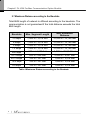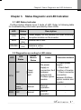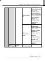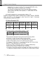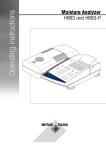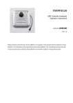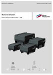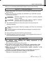
1
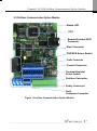
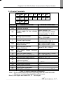
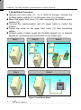
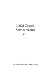
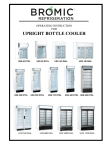
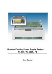
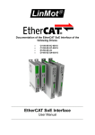
SAFETY PRECAUTIONS Thank you for purchasing iG5A Series Profibus Communication Module SAFETY PRECAUTIONS Always follow safety instructions to prevent accidents and potential hazards from occurring. Safety precautions are classified into “WARNING” and “CAUTION” and their meanings are as follows: operation may result in serious personal WARNING Improper injury or death. operation may result in slight to medium CAUTION Improper personal injury or property damage. The indicated illustrations on the product and in the manual have the following meanings. Danger may be present. Read the message and follow the instructions carefully. Particular attention should be paid because danger of an electric shock may be present. Keep operating instructions handy for quick reference. Read the operating instructions carefully to fully understand the functions of the SV-iG5A series and to use it properly. CAUTION Be cautious, when handling communication module. the CMOS components of the Static may lead to malfunctioning of the product. Turn off the inverter power, when changing the communication cable. Otherwise, you may damage the module or a communication error may occur. Make sure to insert the Communication module connector to the inverter precisely. Otherwise, you may damage the module or a communication error may occur. Check the parameter unit before setting up the parameter. Otherwise, a communication error may occur. i Table of Contents Table of Contents Chapter 1. Overview ........................................................................................ 1 1.1What are the Benefits of Using Profibus option module? .............. 1 1.2Unpacking the drive ...................................................................... 1 Chapter 2. SV-iG5A Profibus Communication Option Module.................... 2 2.1Technical Data .............................................................................. 2 2.2Profibus Communication Option Module ...................................... 3 2.3Profibus Terminals ........................................................................ 4 2.4Control Terminals ..........................................................................5 2.5Installation Procedure ................................................................... 6 2.6Instruction for installation .............................................................. 7 2.7Maximum distance according to the baudrate .............................. 8 Chapter 3. Status Diagnostic and LED Indication ........................................ 9 3.1LED Status Indicator ..................................................................... 9 3.2Option Module Diagnostics according to LED status .................... 9 Chapter 4. Inverter Parameter ........................................................... 12 4.1Profibus Communication Parameter List .................................... 12 4.2Profibus Communication Parameters ......................................... 14 4.2.1 Communication option module name – C1 ............................. 14 4.2.2 Operation setting method - drv ................................................ 14 4.2.3 Frequency setting method - Frq .............................................. 14 4.2.4 Selection of operation in lost command - I62 .......................... 14 4.2.5 Decision time for lost command - I63 ...................................... 15 4.2.6 Version of Profibus option module – C2 .................................. 15 4.2.7 Station ID setting – C3 ............................................................ 15 4.2.8 LED indication for communication status – C5 ........................ 16 4.2.9 The number of Para Status setting – C30 ............................... 16 4.2.10 Para Status 1~8 – C31~C38 ................................................... 17 4.2.11 Number of Para Control setting – C50 .................................... 17 4.2.12 Para Control 1~8 – C51~C58 .................................................. 18 4.2.13 Comm UpDate – C99.............................................................. 19 Chapter 5. GSD File (Electronic Data Sheets) ............................................. 20 ii Chapter1. Overview Chapter 1. Overview This Profibus communication option module (abbreviated Profibus option module) allows a SV-iG5A inverter to be connected to Profibus network. 1.1 What are the Benefits of Using Profibus Option Module? Profibus option module allows a controlling and monitoring of inverter to be controlled via sequence program of PLC or Profibus Master Module. It helps to reduce the installation cost since multiple connections can be implemented with a communication line. In addition, the wiring is simple so installation time will be reduced and maintenance will be easier. Factory automation can be easily implemented because it can control the inverter with auxiliary devices of PLC and operates with top devices as PC, etc. 1.2 Unpacking the Drive The Profibus option module is delivered in a package that contains the following items. -. Profibus Communication Option Module (1) -. Profibus Communication Option Module User Manual (1) -. Fixing Screw M3 (2) 1 Chapter2. SV-iG5A Profibus Communication Option Module Chapter 2. SV-iG5A Option Module Profibus Communication 2.1 Technical Data Device Type Profibus DP Slave Auto Baudrate Detect Supported mode Synchronization Mode Supported mode Freeze Mode Supported mode Max. Input Length 8 words Max. Output Length 8 words Baudrate Support 9.6K, 19.2K, 93.75K, 187.5K, 500K, 1.5M, 3M, 6M, 12M Modular Station Supported Max. Module 2 Max. Connectable Number of Nodes Max. 32 nodes without repeater (including master module) LED 3 LEDs (ONLINE, ERR, and CPU) Communication Connector 5-pin removable connector Table 1 Technical Data 2 Chapter2. SV-iG5A Profibus Communication Option Module 2.2 Profibus Communication Option Module Status LED CPU Remote/Portabel KPD Connector Main Connector PNP/NPN Select Switch Fault Contactor Control Connector Terminal Resistor Select Switch Profibus Connector Safety Connector Fault Contactor Connector Figure 1 Profibus Communication Option Module 3 Chapter2. SV-iG5A Profibus Communication Option Module 2.3 Profibus Terminals ① ②③④ ⑤ Figure 2 Profibus Terminals No. Signal Description 1 B1 Send/Receive data Plus 1 2 A1 Send/Receive data Negative 1 3 SH Shielded Ground 4 B2 Send/Receive data Plus 2 5 A2 Send/Receive data Negative 2 Table 2 Signal Description 4 Chapter2. SV-iG5A Profibus Communication Option Module 2.4 Control Terminals MO MG 24 P1 P2 CM P3 P4 VR V1 CM I AM FI FO CM SA SB SC Terminals Names of Terminal P1 ~ P4 Multi-function input terminal 1-4 CM Common terminal VR V1 I AM MO MG 24 3A 3B 3C FI FO SA SB SC Electrical Information Output voltage: 12V Power supply for Aux. volume Max. output current: 10mA resistor Volume resistor: 1 ~ 5 kΩ Max. input voltage: Voltage input terminal -10V ~ +10V input 0 ~ 20mA input Current input terminal Internal resistor: 250 Ω Multi-function analog Max. output voltage: 11[V] output terminal Max. output current: 10mA Multi-function terminal Below DC 26V, 100mA (Open Collector) Aux. power supply common terminal Aux. 24V power supply Max. output current: 100mA Multi-function relay output A Below AC 250V, 1A Multi-function relay output B Below DC 30V, 1A Multi-function relay common terminal Pulse input terminal 0 ~ 50kHz Pulse output terminal 0~7 Safety input command A Safety input command B Safety Power Supply Max. output current: 10mA Table 3 Control Terminals Information Note 1) Tie the control wires more than 15cm away from the control terminals. Otherwise, it interfere the reinstallation of front cover. Note 2) Use copper wire rated 600V, 75 ℃ and higher. 5 Chapter2. SV-iG5A Profibus Communication Option Module 2.5Installation Procedure Remove the front cover (②, ③) of iG5A for Europe. Connect the Profibus option module (④) on the inner cover (⑤) of inverter. Mount the upper front cover (②) after connecting the profibus option module (④). Connect the communication and I/O signal cable to control the inverter. Fasten the screw on the upper front cover (③) after connecting cables. Profibus option module needs the Portable keypad (⑥) or Remote keypad for monitoring since the module is non-loader type. Step 1 Step 2 Step 3 ② ① ③ ④ ⑤ Step 4 Step 5 ⑥ Figure 3 Installation Steps 6 Chapter2. SV-iG5A Profibus Communication Option Module 2.6 Instruction for installation Warning) Make sure that connect Profibus option module after inverter power is disconnected. Do not install or remove Profibus option module while the power is ON. Otherwise, both Profibus option module and the inverter may be damaged. Install or remove Profibus option module when the condenser of the inverter has been fully discharged. When building a network, make sure to connect the termination resistor to reduce the noise at Profibus option module at the end of the network. Turn on the termination resistor switch on Profibus option module. Termination resistor 220 Ω and 1/8W will be connected between A1 and B1. Termination Switch Termination Switch OFF OFF Node 2 … … Node N - 1 Node 1 Node N Termination Resistor Switch ON Termination Resistor Switch ON 22 0 ohm 1/8 W 22 0 ohm 1/8 W Figure 4 Termination Resistor 7 Chapter2. SV-iG5A Profibus Communication Option Module 2.7 Maximum Distance according to the Baudrate Total BUS length of network is differed according to the baudrate. The communication is not guaranteed if the total distance exceeds the total BUS length. Baudrate Max. Segment Length 12 Mbps 1,000 m / 3,278 feet Max. Extension Distance 10,000 m / 32,786 feet 6 Mbps 1,000 m / 3,278 feet 10,000 m / 32,786 feet 3 Mbps 1,000 m / 3,278 feet 10,000 m / 32,786 feet 1.5 Mbps 1,000 m / 3,278 feet 10,000 m / 32,786 feet 500 kbps 400 m / 1,311 feet 4,000 m / 13,114 feet 187.5 kbps 200 m / 655 feet 2,000 m / 6,557 feet 93.75 kbps 100 m / 327 feet 1,000 m / 3,278 feet 19.2 kbps 100 m / 327 feet 1,000 m / 3,278 feet 9.6 kbps 100 m / 327 feet 1,000 m / 3,278 feet Table 4 Maximum Distance according to the Baudrate 8 Chapter3. Status Diagnostic and LED Indication Chapter 3. Status Diagnostic and LED Indication 3.1 LED Status Indicator Profibus Option Module have 3 kinds of LED. Refer to following table for troubleshooting information provided by there LEDs. LED CPU ERR ONLINE Status Description Steady (On) Steady (On) Steady (On) Power supply on the module OK after mounting the option module on the inverter. Module has a fault. Module is online. Table 5 LED Indication 3.2 Diagnostics according to LED status LED LED Status Cause Corrective Actions OFF Power supply fault ☞Check power supply. No power ☞Check fault supply or connection fault function of inverter. between ☞Check connector inverter and connection Profibus option between Profibus module option module and inverter. Blinking every second Normal Normal operation - OFF Normal Normal operation - CPU ERR Option Module Status 9 Chapter3. Status Diagnostic and LED Indication Blinking every second with CPU LED Blinking every 2 seconds ERR Blinking every 3 second Communication error with inverter Communication is not available between inverter and option module. CONFIG ERROR Configuration Data is incorrect setting between Master and Inverter. Configuration information changed Station ID, number of Status, and number of Control value is changed by Keypad. Communication is not started from master. ONLINE OFF Off-Line Communication connector has a fault. There is no master in the network. 10 ☞Check fault function of inverter. ☞Check connector connection between Profibus option module and inverter. ☞Check configuration information set in master and inverter. ☞Perform Comm Update or reset the inverter if Station ID (C 3), number of Status (C 30), and number of Control (C 50) are changed. ☞Start the communication from Master. ☞Check the connection between pin number of connector and termination resistor. ☞There is no designated master or master has a fault. Chapter3. Status Diagnostic and LED Indication Wrong Station ID Network Configuration Fault ON On-Line ☞Check the station ID between designated Profibus option module station ID set in configuration tool and station ID set in keypad of inverter. In addition, check that station ID is unique in the network. ☞Check that it exceeds max. length of segment. ☞Check that number of station exceeds 32 stations including repeater in a segment. ☞Check that the number of station exceeds 126 stations including repeater in a network. IO Data Exchange state - Table 6 Diagnostics according to LED Status 11 Chapter4. Inverter Parameter Chapter 4. Inverter Parameter 4.1 Profibus Communication Parameter List Code drv 12 Name of Parameter Operation Setting Method Default Value Range 0. Keypad 1. Fx/Rx-1 1. Fx/Rx2. Fx/Rx-2 1 3. RS485 4. FieldBus 0. Keypad-1 1. Keypad-2 2. -10~10V 3. 0~10V 4. 0~20mA 0. Keypad- 5. "2" + "4" 6. "3" + "4" 1 7. RS485 8. Digital Volume 9. FieldBus 10. Pulse Description Select No.4 FieldBus if you want to command the operation of inverter via Profibus. Select No.9 FieldBus if you want to command the frequency of inverter via Profibus. Frq Frequency Setting Method C1 FieldBus Option Name - - ‘PnEt’ is indicated when Profibus option module is mounted. C2 Comm. Option Module Version - - S/W version of Profibus option module is indicated. C3 Station ID Setting 1 1 ~ 125 C5 FBus LED - - LED status of Profibus option module is displayed. Chapter4. Inverter Parameter C30 C31 C32 C33 C34 C35 C36 C37 C38 C50 C51 C52 C53 C54 C55 C56 C57 C58 C99 Number of Para Status Setting Para Status-1 Para Status-2 Para Status-3 Para Status-4 Para Status-5 Para Status-6 Para Status-7 Para Status-8 Number of Para Control Para Control-1 Para Control-2 Para Control-3 Para Control-4 Para Control-5 Para Control-6 Para Control-7 Para Control-8 Comm Update 3 h000A h000E h000F h0000 h0000 h0000 h0000 h0000 2 0~8 0~hFFFF 0~hFFFF 0~hFFFF 0~hFFFF 0~hFFFF 0~hFFFF 0~hFFFF 0~hFFFF 0~8 h0005 h0006 h0000 h0000 0~hFFFF 0~hFFFF 0~hFFFF 0~hFFFF h0000 h0000 h0000 h0000 0~hFFFF 0~hFFFF 0~hFFFF 0~hFFFF 0. No 0. No 1. Yes I62 I63 Selection of 0. None Operation in 0. None 1. Free-Run Lost 2. Dec Command Decision Time ~ 120.0 for Lost 1.0 sec 0.1 sec Command Set the number of Status used. Set the address of status read from Profibus master. Set the number of Control. Set the address of control controlled by Profibus master. Use when comm. update Profibus option module. ‘0’ is displayed automatically after comm. update if C99 set to 1. Set the inverter operation when Lost Command is occurred. Set the decision time for Lost Command. Table 7 Inverter Parameters 13 Chapter4. Inverter Parameter 4.2 Profibus Communication Parameters 4.2.1Communication option module name - C 3 FBus ID It displays the name of option module installed on the inverter. It displays ‘PnEt’ when Profibus option module is installed correctly and it has no fault. 4.2.2 Operation setting method - drv It sets the operation setting method of inverter. To control inverter operation through Profibus communication, set ‘drv’ to ‘4’. 4.2.3 Frequency setting method - Frq It sets the frequency setting method of inverter. To control inverter frequency through Profibus, set ‘Frq’ to ‘9’. 4.2.4 Selection of operation in lost command - I62 drv Frq I62 I63 Operation setting method Frequency setting method Selection of operation in Lost Command Decision time for Lost Command It designates operation method when communication is lost during decision time for Lost command. To use this function, ‘drv’ have to be set to ‘4’ (FieldBus) or ‘Frq’ to ‘9’ (FieldBus). Selection of operation in Lost Command 0 (None) Continuing operation 1 (FreeRun) Free run to stop 2 (Stop) Deceleration to stop 14 Chapter4. Inverter Parameter 4.2.5Decision time for lost command - I63 To use this function, ‘drv’ have to be set to ‘4’ (FieldBus) or ‘Frq’ to ‘9’ (FieldBus). drv Frq I62 I63 Operation setting method Frequency setting method Selection of operation in Lost Command Decision time for Lost Command If communication restarts in a decision time of Lost Command, it is not recognized for error. (①) Communication Status Lost Command Decision time for Lost Command Lost Command Decision time for lost Command Recognition of ① Lost Command Figure 5 Lost Command Recognition 4.2.6 Version of Profibus option module – C2 It displays the version of Profibus option module installed on the inverter. 4.2.7 Station ID setting – C3 C3 Station ID setting C99 Comm Update It sets Station ID of Profibus option module. It can set station ID from 1 to 125. Station ID cannot be duplicated. Check if Station ID is not 15 Chapter4. Inverter Parameter duplicated in the network. If station ID is changed, ERR LED on the Profibus option module is flickered every 3 seconds. The number of changed Para Control must be applied to Profibus option module. Set C99 (Comm Update) to ‘1’ when Station ID had been changed. 4.2.8 LED indication for communication status – C5 Profibus communication option module have 3 LEDs, (blank), ONLINE, ERR, and CPU, on the keypad in order from left to right. It indicates communication status by On/Off. C5 Status Example) 0101 - LED type Keypad Value Status Blank ON-LINE (Green) ERR (Red) CPU (Green) 0 1 0 1 Reserved ON OFF ON 4.2.9 The number of Para Status setting – C30 C30 Number of Para Status setting C31~C38 Para Status1~Status8 setting This parameter determines that inverter sends how many status information to master through Profibus communication. It can set the number from 0 to 8. Para Status has to be set as the number of Para Status. (from C31 to C38 as preset number) For example, If C30 sets to ‘3’, Para Status set from C31 to C33. If C30 sets to ‘6’, Para Status set from C31 to C36. If C30 (the number of Parameter status) is changed, ERR LED on Profibus option module is flickered every 3 seconds. If ‘Number of Para Status setting’ is changed, set ‘C99(Comm Update)’ to ‘1’ to apply the changed number of Para Status to Profibus option module. 16 Chapter4. Inverter Parameter 4.2.10 Para Status 1~8 – C31~C38 C30 Number of Para Status setting C31~C38 Para Status1~Status8 setting It determines that what status information will be sent to master through Profibus communication. Para Status 1~8 sets with the type of inverter address. The address is for inverter common area and inverter keypad parameter. If keypad parameter address is used, it will be inputted the type of (h0A x h1000) + (‘Group number’ x h100) + (‘Code number’). For example, if maximum frequency of No. 21 at F group set to Para Status-1, it has to be set to hA215. h0A x h1000 + h02 x h100 + h15(Dec 21) = hA215 Group DRV F H IO COM Group Number 1 2 3 4 5 4.2.11 Number of Para Control setting – C50 C50 Number of Para Control setting C51~C58 Para Control 1 ~ Control 8 setting C99 Comm Update It determines that master sends how many control information to inverter through Profibus communication. It can set the number from 0 to 8. Para Control has to be set as the number of Para Control. (From C51 to C58 as preset number) For example, If C50 sets to ‘2’, Para Status set from C51 to C52. If C50 sets to ‘5’, Para Status set from C51 to C55. 17 Chapter4. Inverter Parameter If C50 (the number of Para Control) is changed, ERR LED on Profibus option module is flickered every 3 seconds. If ‘Number of Para Control setting’ is changed, set ‘C99(Comm Update)’ to ‘1’ to apply the changed number of Para Control to Profibus option module. 4.2.12 Para Control 1~8 – C51~C58 C50 Number of Para Control setting C51~C58 Para Control 1~Control 8 setting It determines that what control information will be sent to inverter through Profibus communication. Para Control 1 ~ 8 sets with the type of inverter address. The address is for inverter common area and inverter keypad parameter. If keypad parameter address is used, it will be inputted the type of (h0A x h1000) + (‘Group number’ x h100) + (‘’Code number’). For example, if maximum frequency of No.34 at IO group set to Para Control-1, it has to be set to hA422. h0A x h1000 + h04 x h100 + h22 (Dec 34) = hA422 Group DRV F H IO COM 18 Group Number 1 2 3 4 5 Chapter4. Inverter Parameter 4.2.13 Comm UpDate – C99 C3 Station ID setting C30 The number of Para Status setting C50 The number of Para Control setting C99 Comm UpDate After changing Station ID, the number of Para Status, and the number of Para Control, set the Comm Update to ‘1’. The changed value will be applied to Profibus option module after Comm Update. 19 Chapter 5. GSD File Chapter 5. GSD File (Electronic Data Sheets) It contains the information of Profibus option module. The profibus configuration software needs GSD file. You can download GSD file from technical support in LSIS website. (http://eng.lsis.biz) 20 Warranty Warranty Maker Model No. LS Industrial Systems Co., Ltd. SV-iG5A Profibus Communication Option Module Name Installation Date Warranty Period Customer Address Information Tel. Name Sales Office Address (Distributor) Tel. Warranty period is 12 months after installation or 18 months after manufactured when the installation date is unidentified. However, the guarantee term may vary on the sales term. IN-WARRANTY service information If the defective part has been identified under normal and proper use within the guarantee term, contact your local authorized LS distributor or LS Service center. OUT-OF WARRANTY service information The guarantee will not apply in the following cases, even if the guarantee term has not expired. Damage was caused by misuse, negligence or accident. Damage was caused by abnormal voltage and peripheral devices’ malfunction (failure). Damage was caused by an earthquake, fire, flooding, lightning, or other natural calamities. When LS nameplate is not attached. When the warranty period has expired. A