1
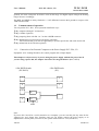
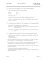
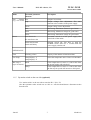
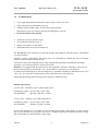
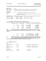
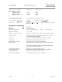
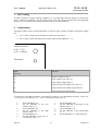
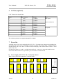
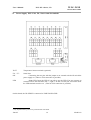
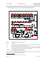
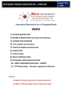
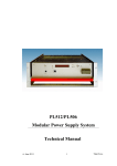
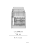
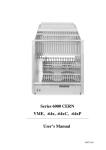
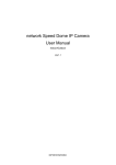
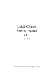
Modular Floating Power Supply System
PL 500 / PL 6021, F8
User Manual
User’s Manual
W-Ie–Ne-R
PL5 / PL 6 Series, F8
Plein & Baus GmbH
Modular Power Supply System Series PL500 / PL6021,
Floating
F8
3U and 6 U Size
General Remarks
The only purpose of this manual is a description of the product. It must not be interpreted as a
declaration of conformity for this product including the product and software. W-Ie-Ne-R revises
this product and manual without notice. Differences of the description in manual and product are
possible. W-Ie-Ne-R excludes completely any liability for loss of profits, loss of business, loss of
use or data, interrupt of business, or for indirect, special incidental, or consequential damages of any
kind, even if W-Ie-Ne-R has been advises of the possibility of such damages arising from any defect
or error in this manual or product. Any use of the product which may influence health of human
beings requires the express written permission of W-Ie-Ne-R. Products mentioned in this manual are
mentioned for identification purposes only. Product names appearing in this manual may or may not
be registered trademarks or copyrights of their respective companies. No part of this product,
including the product and the software may be reproduced, transmitted, transcribed, stored in a
retrieval system, or translated into any language in any form by any means with the express written
permission of W-Ie-Ne-R.
Mains Voltage and Connection
The Power supplies are equipped with a “World”- mains input, which works properly form 94VAC up
to 264VAC and within a frequency range of 47 to 63Hz.
Before connecting to the mains please double-check correspondence.
The mains input connection at the power supply side is done with a 3-pin Hirschmann connector
(input current max. 16 A) or power terminals.
Hirschmann
Pin No.
Signal
Description
Color of the Wire
Pin 1
L
Phase
black or brown
Pin 2
N
Return, Neutral
blue
Pin 3
Earth
not connected
PE
Protective Earth
green/yellow
Safety
After connecting the PL5 / PL6, F8 to the mains, the mains input module is powered permanently.
Filter and storage capacitors of the power factor correction module are charged with about 400VDC.
The DC-On-Signal as well as a power switch at control board (if any installed) operates as a DC
on/off switch only and not as a mains breaker. Therefore it becomes dangerous if the box cover is
open. In this case a lot of components on high voltage potential get touchable!
Before starting any kind of work inside the power box remove the PL5 / PL6, F8 from
mains and wait a couple of minutes with your activities! Discharge the primary DC
Filtercapacitors by use of a well isolated 22 ohm 10W resistor.
June 05
2
*00493.A2
User’s Manual
PL5 / PL 6 Series, F8
W-Ie–Ne-R
Plein & Baus GmbH
Declaration of Conformity
Art. 10.2 of 89/336 and 89/392 / ECC
W-Ie-Ne-R
Plein & Baus GmbH
declare under our own responsibility that the product
PL5 / PL6, F8
Items: 0P00.xxxx; 0P01.xxxx; 0P04.xxxx
to which this declaration relates, is in conformity with the following standards or normative documents :
1. EN 61 000-6-3:2001 (EN 50 022 Cl. B; EN 61 000 -3 –2, -3 -3)
2. EN 61 000-6-2:2001 (EN 61 000 -4 –1... –6, -11)
3. EN 60950
Conditions:
This unit is not a final product and is foreseen for use inside a closed cabinet. The supplying of loads
over long distances (>3m) needs possibly additional RF rejection hardware to get in conformity of the
definition.
Admitted for powering by all mains.
Name and signature of authorized person
Place and Date
Juergen Baus
Techn. Director
June 05
Febr. 2001
3
*00493.A2
User’s Manual
PL5 / PL 6 Series, F8
W-Ie–Ne-R
Plein & Baus GmbH
Table of contents:
1Device description.................................................................................................................................. 4
1.1Commencement of operation...............................................................................................................5
1.1.1Connection of an Personal Computer to the Power Supply PL5 / PL6, F8............................ 5
1.1.2Control of the Power Supply PL5 / PL6, F8 via CAN-Bus (optional)....................................6
1.1.3Control of the Power Supply PL5 / PL6, F8 without PC or Control panel (display)..............6
1.1.4Control of the Power Supplies PL5 / PL6, F8 with the Alphanumeric Control......................6
1.1.5By mains switch on the rear side (optional)............................................................................. 7
1.2Technical Data.....................................................................................................................................8
1.3DC Output of different modules and floating range............................................................................9
1.4Regulation (PL 6021).......................................................................................................................... 9
2 Power Supply Block diagram.............................................................................................................. 12
3Air Cooling........................................................................................................................................... 13
4Adjustments.......................................................................................................................................... 13
6CANbus (optional)............................................................................................................................... 15
7Power bin.............................................................................................................................................. 15
7.1Power Supply PL5 / PL6, F8, Connection scheme........................................................................ 15
7.2Power Supply PL5 / PL6, F8, Sense control terminals.................................................................. 16
7.3Power Supply PL5 / PL6, F8, Sense control terminals (improved)............................................... 17
8Example for pinning............................................................................................................................. 18
1
Device description
The PL5 / PL6, F8 can control up to 8 different floating outputs. Referring to the ground reference
(VME-LOGIC-GND, pin 30 of the 37 pin D-Sub connector) the maximal floating voltage for proper
regulation should not exceed +/-10V for the 2... 7V MEH outputs and also for MDL and MDH
June 05
4
*00493.A2
User’s Manual
W-Ie–Ne-R
PL5 / PL 6 Series, F8
Plein & Baus GmbH
grounds. All sense- and power levels have to be in this range. For higher output voltages the floating
ranges increase accordingly.
The MDL and MDH are always limited to +/-10V difference between their grounds in respect to the
VME-LOGIC-GND.
1.1
Commencement of operation
You can put the PL5 / PL6, F8 in operation in different ways:
1: By computer (through V 24 interface)
2: By CANbus (optional)
3: By jumpering Pin 8 with Pin 2 or 7 on the 9 DSUB connector
4: By alphanumerical control panel with display (optional)
The control board gives also the opportunity to operate special fans and watch for fan fail
5: By mainswitch on the rearside (optional)
1.1.1
Connection of an Personal Computer to the Power Supply PL5 / PL6, F8
Equipment: A PC running Windows, the control program and a simple adapter.
This adapter is only necessary if you are using the power supply without the power bin! If
you are using a power bin, the adapter electronics are integrated there. (See 7.2/7.3)
9 Pin DSUB female
(PL 500 F8)
9 Pin DSUB male
(PC)
3
2
8
3
7
1kΩ
5
6
1 kΩ
100nF
Note:
If you use Pin 3 and 8 for a serial connection to a computer, you can’t use this pins any more for the
„Remote On“ and „Status Out“ functions and you can neither connect the power supply to an
alphanumeric control panel (see below 4) nor operate with remote on / off (see below 3).
June 05
5
*00493.A2
User’s Manual
PL5 / PL 6 Series, F8
W-Ie–Ne-R
Plein & Baus GmbH
1.1.2
Control of the Power Supply PL5 / PL6, F8 via CAN-Bus (optional)
The CAN Bus Signals are provided on the 9 Pin DSUB:
CAN_H:
Pin 5
CAN_L:
Pin 9
CAN_GND:
Pin 4
The software protocol is described in a separate document (Part No *00183)
CANbus is an independent port. It may used also in combination with the operation
modes of 1, 3, 4, and 5
1.1.3
Control of the Power Supply PL5 / PL6, F8 without PC or Control panel (display)
There is a remote on/off input and a status output function:
Remote On:
9 Pin DSUB: Close a “make” contact or switch between Pin 8 (Serial
Data In) and Pin 2 or 7.
Status Output:
9 Pin DSUB: Connect a LED between Pin 3 (Serial Data Out,+) and
Pin 1 or 6.
1.1.4
Control of the Power Supplies PL5 / PL6, F8 with the Alphanumeric Control
Many power supply parameters may be changed via the alphanumeric control of the
connected fan tray.
The general procedure is:
-
Switch the POWER and the MODE switch up simultaneous for 5 seconds. The display
shows „Config: Wait....“ and „Config: Ready !“. Then release both switches.
-
If a sub-menu exists, you may now select the sub-menu item (MODE switch up/down). If
no sub-menu exists, you may change the parameter value (MODE switch up/down)
-
To change a parameter of a sub-menu, select it (POWER switch up). The selected
parameter is flashing now.
-
You may alter the parameter now (MODE switch up/down)
-
After finishing the parameter programming, leave the submenu or configuration menu
(POWER switch down).
June 05
6
*00493.A2
User’s Manual
PL5 / PL 6 Series, F8
W-Ie–Ne-R
Plein & Baus GmbH
Mode
associated parameter
submenu
Description
Any
Voltage Ilim
(e.g. +5V or U0)
Uadj
Power
Output Current limit
Output voltage fine adjustment. The same
function as the switches in the power supply
Unom
Output voltage coarse adjustment.
Imax
Monitoring: Maximum current for good status.
Umin
Monitoring: Minimum voltage for good status.
Umax:
Monitoring: Maximum voltage for good status.
Auto Power On
Automatic switch on of the power supply after
come back of the mains
No Auto Power On
Switch Off Normal
Delayed switch off: You have to push the
POWER switch down for 5 seconds until the
power supply switches off
Switch Off Delay
OPTIONALLY:
Fans
Watching x Fans
Display of the number of monitored fans
Fan Temp
Temp Display: °C
Select the temperature unit: Celsius or Fahrenheit
Temp Display: °F
Bin Temp x
PsOff
If the temperature of sensor x is above this limit,
the power supply will switch off.
FanUp
If the temperature of sensor x is above this limit,
the fan tray fan speed will increase to full speed.
(up to 8 sensors)
1.1.5
By mains switch on the rear side (optional)
Use “mains switch” at the rear side to start the PL5 / PL6, F8.
Also this optional rocker switch acts as a DC on / off switch and doesn’t disconnect mains
from the unit
June 05
7
*00493.A2
User’s Manual
PL5 / PL 6 Series, F8
W-Ie–Ne-R
Plein & Baus GmbH
1.2
Technical Data
•
Up to eight independent potential free outputs with >5 kW at 230 VAC
•
Fully controlled, programmable trip levels
•
Voltage ramp up within (50ms fix) monotony and synchrony,
Ramp down as fast trip. Output capacitors discharging by crow bar
•
DC on/off channel wise possible
•
Extremely low noise and low ripple
•
CE conform EN 50081/82 part 1
•
Safety in accordance to EN 60950
•
Sinusoidal mains current to EN 61000-3-2
The PL 500 has been constructed to provide external load channels with high power consumption
over long distances.
Voltages, currents, temperatures and output power are controlled by internal processor and illegal
modes as well as failure will be detected.
A fast sense circuit and a delayed remote-sense compensation guarantees continuously and stable
operation, even with long inductive wiring to the loads.
PL 6021 is not equipped with the remote sense slow regulation. Therefore UEP 6021 is foreseen for
either powering loads in sensed mode over a short distance or unsensed over all distances.
A control board with display for data and diagnostic is optionally available for installation in the PL5
/ PL6, F8, -19” power bin. Connection has to be achieved by use of the V24 loop.
Optional programming and monitoring can be done by CANbus interface.
Module cage formats
6 U box: max. 10 modules, up to 5..6kW output power
Connections / plugs: 10 pins 250A, 8 pins 150A
Size (WxHxD):
434 mm x 260 mm x 255mm
3 U box: max. 5 modules, up to 2kW output power
Connection / plugs:
10 pins 250A, 8 pins 150A
Size (WxHxD):
434mm x 132mm x 255mm
3U box with alternative C or H input, 6U box suitable for all inputs. Plugs until 16A input current,
above 16A terminals with 2m power cord, fixed . Available output power depends on input voltage
and is listed above for the full mains voltage range.
June 05
8
*00493.A2
User’s Manual
W-Ie–Ne-R
PL5 / PL 6 Series, F8
Plein & Baus GmbH
Mains input
CE
H/K Sinussoidal:
EN 60555, IEC 555 pow. fact.0.95(230VAC), 92..264 VAC, 16/32A
Inrush current:
limited by softstart circuit below nominal input current (cold unit)
Isolation CE
Inp.-outp.:
acc. to
Fuse:
EN 60950, ISO 380, VDE 0805, UL 1950, C22.2.950
extern 16A or 32A according to typing sticker (only special ones with
internal slow blow fuses)
DC Output power with different mains inputs (16A/32A), calculated with typical efficiency of 72%
115VAC / 1.325W
230VAC / 2.650W
3U power box, 16A input
115VAC / 2.650W
230VAC / 5.300W
6U power box, 32A input
1.3
DC Output of different modules and floating range
The listed “floating range” refers always to the VME-LOGIC-GND of the 37 pin Sub D connector
min. to max. range
2
4
7
12
30
-
7,0V
10,0V
16V
30V
60V
floating range
+/- 10V
+/- 15V
+/- 20V
+/- 30V
+/- 70V
max. output
(with C, E, H, K mains input)
115A / 550W
85A / 650W
46A / 550W
23A / 550W
13,5A / 650W
type MEH
type MEH
type MEH
type MEH
type MEH
Note:
The max. floating range of MEH modules is to understand that all output levels
have to be inside the voltage range. Also if outputs should operate in +/- or other
cascading
condition.
2 7
7 -
7.0V
24V
30V
+/- 10V
+/- 10V
+/- 10V
(±)20A/140W(280W)
(±)11.5A/140W.(280W)
(±) 7.4A/180W.(360W)
type MDH
type MDL
type MDL
Note:
The max. floating range of MDL and MDH modules concerns only the difference
between the “grounds” of the module and the VME-LOGIC-GND. The “ground”
pins of the double module are marked with a * on the type plate. They are not
connected together and passed to the output connector pins separate.
1.4
Regulation (PL 6021)
Static:
MEH 550W/650W
<25mV
(± 100% load, ± full mains range)
MDH 20A:
<0.1%
(± 100% load, ± full mains range)
MDL (11.5A/7.4A)
<0.1%
(± 100% load, ± full mains range)
MEH, MDH:
< 100mV
(± 25% load)
MDL (11.5A/7.4A):
<0,7%
(± 25% load)
Dynamic:
June 05
9
*00493.A2
User’s Manual
W-Ie–Ne-R
PL5 / PL 6 Series, F8
Plein & Baus GmbH
Recovery time ±25% load:
(Power Supply terminals)
Modules 550W
Modules 650W
MDL (11.5A/7.4A):
within ±1%
within ±0,1%
0,2ms
0,5ms
0,0ms
0,5ms
1,0ms
1,0ms
Sense compensation range:
up to maximum module voltage range
Noise and ripple, 50cm wire:
10m wire:
Conditions,
at load site:
< 10mVpp
(0-20MHz) 3mVrms (0-2MHz)
< 3mVpp
(0-300MHz)
Parallel (X) >330µF and >1µF ceramic, 100nF HF- conducting
to case (Y)
Electromagnetic Compatibility
Emission :
Immunity:
CE
CE
EN 50081-1,
EN 50082-1 or 2
Operation temperature:
0....50°C without derating,
storage:
-30°C till 85°C
Temp.- Coefficient:
< 0.2% / 10K
Stability (Condition const.):
<5mV or 0.1% within 24 h, <25mV or 0.5% within 6 month
Current limiting:
100% of nominal values, programmable to lower values
via interface or display tableau.
Voltage rise:
monotony, synchrony, within 50 ms (factory settings),
Voltage off:
discharge of output capacitors after DC off.
Over voltage protection:
Factory settings to 125% of nominal values
Status control:
within 5ms if >2% deviation from nominal or programmed
values, after overload, overheat, overvoltage, undervoltage
All trip thresholds programmable
Interlock input (option):
High level or open: All outputs DC off
AC-fail and Sys-Reset:
Generation according to VME Specification, optional
Temperatur limits:
110°C heat sink, 70°C ambient intern
M T B F at 40° ambient:
>65.000h (blower), electronics> 100.000h
June 05
10
*00493.A2
User’s Manual
PL5 / PL 6 Series, F8
W-Ie–Ne-R
Plein & Baus GmbH
June 05
11
*00493.A2
User’s Manual
W-Ie–Ne-R
PL5 / PL 6 Series, F8
Plein & Baus GmbH
2
Power Supply Block diagram
90 (94) ... 264 VAC input
slow integral regulator (PL 500)
Remote sense line
fast regulator (PL 500 /PL 6021)
rectifire
and
outputfilter
+
U load side
June 05
12
−
*00493.A2
User’s Manual
W-Ie–Ne-R
PL5 / PL 6 Series, F8
Plein & Baus GmbH
3
Air Cooling
In order to produce a proper working condition it is very important, that the cooling air can pass the
device without any handicap. The air intake comes from the bottom and will leave the equipment
from its top, so it must be assured that the airflow doesn’t hit any hindrance.
4
Adjustments
All output voltages can be adjusted manually via the two rotary switches situated on the power supply
top.
1. the 1. rotary switch selects the function which has to be adjust
2. the 2. rotary switch will change the settings when turned (right/left = +/-)
Channel selection
(0:Uo...7:U7)
(A-D: CANbus)
Adjustment
+
Mode
Function
Selection
0-7
Adjust Voltage of U0-U7
A
CAN Address (low, Bit 0-3)
B
CAN Address (high, Bit 4-6)
C
CAN General Call Address (low, Bit 0-3)
D
CAN General Call Address (high, Bit 4-6)
E
CAN Transmission Speed Index
To change the CAN-Bus parameters, the following sequence is recommended (Example: address 58
= 0x3A, general call address 127 = 0x7F, transmission speed index 1):
1.
2.
3.
4.
5.
6.
June 05
Set the MODE to “A”
Set the ADJUST to the low
address value (“A”)
Set the MODE to “B”
Set the ADJUST to the high
address value (“3”)
Set the MODE to “C”
Set the ADJUST to the low G.
Call address value (“F”)
7.
8.
9.
10.
11.
13
Set the MODE to “D”
Set the ADJUST to the high G. Call
address value (“7”)
Set the MODE to “E”
Set the ADJUST to the speed index
(“1”)
Set the MODE to “F” (park position)
*00493.A2
User’s Manual
PL5 / PL 6 Series, F8
W-Ie–Ne-R
Plein & Baus GmbH
5
June 05
14
*00493.A2
User’s Manual
W-Ie–Ne-R
PL5 / PL 6 Series, F8
Plein & Baus GmbH
6
CANbus (optional)
CAN Transmission Speed Index
Index
Max. Distance
Bit Rate
Type
high- speed
0
10 m
1.6 Mbit/s
1
40 m
1.0 Mbit/s
2
130 m
500 kbit/s
3
270 m
250 kbit/s
4
530 m
125 kbit/s
5
620 m
100 kbit/s
6
1.300m
50 kbit/s
7
3.300 m
20 kbit/s
8
6.700 m
10 kbit/s
9
10.000 m
5 kbit/s
(needs termination)
low-speed
For software protocol see separate manual No. *00183
7
Power bin
A suitable range of 19” racks equipped with PL 5 / PL 6, F8 counter part connectors and guiding bars
for bearing the power boxes is available. Cooling air intake can be from front or bottom side in
standard power bins. Also when a control board with display will installed either bottom or front
intake may select.
For the power plugs 1 to 9 and 12 are M8 studs and for 10, 11 and 13 to 18 are M6 studs foreseen.
Sense- and control connectors (9 pin and 37 pin) are wired to a terminal board
7.1 Power Supply PL5 / PL6, F8, Connection scheme
Rear view to power bin connectors / terminal studs
18
15
12
9
6
3
-
+
-
+
-
+
17
14
11
8
5
2
-
-
-
-
-
-
16
13
10
7
4
1
+
+
+
+
+
+
June 05
15
D
S
u
b
37pol.
D-Sub
9 pol.
*00493.A2
User’s Manual
PL5 / PL 6 Series, F8
W-Ie–Ne-R
Plein & Baus GmbH
7.2
Power Supply PL5 / PL6, F8, Sense control terminals1
T0-T7
Temperature Sensor terminals (optional)
U0 ... U7:
Sense lines
ON
Connecting the two pins with the jumper or an external switch will switch the
power supply on. (Then no V24 connection is possible).
LED
Status LED. Insert the LED if you wish to use the LED. You may connect an
external LED to the terminals (left: +, right:-). In that case the pcb wire which short
the LED terminals must be cut. . (Then no V24 connection is possible).
On this board, the U0-SENSE is connected to VME-LOGIC-GND.
1
Only implemented in power bins produced after June 2000.
June 05
16
*00493.A2
User’s Manual
PL5 / PL 6 Series, F8
W-Ie–Ne-R
Plein & Baus GmbH
7.3
Power Supply PL5 / PL6, F8, Sense control terminals (improved)2
T0-T7
Temperature Sensor terminals (optional)
U0 ... U7:
Sense lines
ON
Connecting the two pins with the jumper or an external switch will switch the power
supply on. (Then no V24 connection is possible).
LED
Status LED. Insert the LED if you wish to use the LED. You may connect an external
LED to the terminals (left: +, right:-). In that case the pcb wire which short the LED
terminals must be cut. . (Then no V24 connection is possible).
Jumper X1
Pin 1-2 shorted: RS232 functionality
Pin 2-3 shorted: Status LED functionality
On this board, the +/- Sense lines of every channel could be connected to VME-LOGIC-GND
(Jumper X10...X17). At least one jumper must be set.
2
Only implemented in power bins produced after January 2005.
June 05
17
*00493.A2
User’s Manual
PL5 / PL 6 Series, F8
W-Ie–Ne-R
Plein & Baus GmbH
8
Example for pinning
Due to the long range of different configurations there are no pin out fixed.
The real pin assignment is given by the type sticker on rear side of the power box PL 500 / PL 6021.
It is showing voltages and currents with respect to the output number 0... 7 with the corresponding pin
number and polarity.
Each output has a pair of contacts (+/-, floating). The “ground”-pins of MDL/MDH double modules
(which must be used to calculate the floating range) are marked with a *.
115VAC / 1.325W
230VAC / 2.650W
3U power box, 16A input
PL500
:
June 05
18
*00493.A2