1
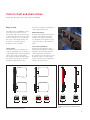
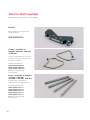
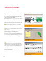
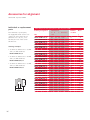
FAG Alignment Tools
Top-Laser: SMARTY2 · TRUMMY2 · INLINE2 · SHIM
Contents
Tools for belt and chain drives
2
Belt pulley alignment device FAG Top-Laser SMARTY2
Belt tension measuring device FAG Top-Laser TRUMMY2
2
5
Tools for shaft couplings
7
Shaft alignment device FAG Top-Laser INLINE2
7
Accessories for alignment
15
Shims FAG Top-Laser SHIM
15
Comparison of ordering designations
17
F’IS products, services and training –
everything from a single source
18
This Technical Product Information contains the current
ordering designations of Schaeffler Group Industrial.
Different designations may be used as appropriate in some
countries (please see the comparison on page 17).
Tools for belt and chain drives
Belt pulley alignment device FAG Top-Laser SMARTY2
FAG Top-Laser SMARTY2
The FAG Top-Laser SMARTY2 is an
economical measuring device for
the alignment of belt pulleys and
chain sprockets.
Through the use of this device, the
wear of belts, belt pulleys, bearings
and seals is reduced. Less vibration
is generated and the running time
and reliability of the machinery is
increased.
Features and advantages
• Parallelism and misalignment of
both pulleys displayed
• Significantly quicker and more
precise than other, conventional
methods
• Suitable for both horizontally and
vertically mounted machinery
• Only one person required for
alignment
• System can also be used on
non-magnetic sprockets or pulleys.
Alignment of belt pulleys
Types of misalignment
Angular misalignment
Main applications
Parallel misalignment
2
Flat belts
Vee belts
Toothed belts
Sprockets
Angular misalignment
+ parallel misalignment
Tools for belt and chain drives
Belt pulley alignment device FAG Top-Laser SMARTY2
Easy to use
This allows simple documentation
of the alignment process.
The FAG Top-Laser SMARTY2 can be
mounted in just a few seconds.
The laser beam can be clearly seen
on the target marks. Once the laser
beam is adjusted to coincide with
the slots in the target marks, the
machine is correctly aligned.
Nothing could be simpler.
Aluminium pulleys
Since the measuring instrument is
so light, the emitter and target
marks can be easily attached to
non-magnetic drive pulleys using
a strong, double-sided adhesive
tape.
Target marks
The target marks are available in
optical and digital form. In the case
of the digital target mark, adjustment
values are shown in real time in
the display. Angular misalignments
are presented in degrees and the
parallel misalignment in mm.
Laser beam adjustment
The laser beam emitted by the
measuring instrument is adjusted
parallel to the magnetic holders
of the measuring instrument.
If a deviation is found, this can be
checked locally on a flat surface
by the operator and readjustment
carried out if necessary.
Alignment example using a belt drive
FAGTop-Laser SMARTY2 in operation
For drives with pulleys of different widths,
the marks should be moved within the target
marks
3
Tools for belt and chain drives
Belt pulley alignment device FAG Top-Laser SMARTY2
Technical data
Laser emitter
Belt pulleys
Laser beam angle
Laser class
Measurement distance
Batteries
Battery life
Output power
Laser wavelength
Housing
Device dimensions
W~H~D
Mass
145 ~ 86 ~ 30 mm
270 g
Targets
2 magnetic target marks
Measurement accuracy
better than 0,5 mm or 0,2°
*)
≥ 60 mm ø
78°
2
10 m
1 ~ R6 (AA) 1,5 V
8 h continuous
< 1 mW
635...670 nm
ABS plastic, aluminium
FAG Top-Laser SMARTY2
*)
General rule for deviations (depending on belt type):
less than 0,25° [4,4 mm/m]
Ordering designation and
scope of delivery:
Laser measuring instrument,
complete, including 2 target marks,
2 batteries and user manual in
padded case:
LASER-SMARTY2
Calibration:
It is recommended that the
FAG Top-Laser SMARTY2 should
be calibrated every two years
(to ISO 9001-2000)
LASER-SMARTY.CALI-CHECK
Replacement part:
1 optical magnetic target mark
LASER-SMARTY2.TARGET
Accessories:
1 digital magnetic target mark incl.
1 case for digital magnetic target
mark and FAG Top-Laser SMARTY2
LASER-SMARTY2.TARGET-DIGITAL
Safety guidelines
Do not look into the laser beam.
Do not point the laser beam into
other persons’ eyes.
4
Digital magnetic target mark (accessory)
Tools for belt and chain drives
Belt tension measuring device FAG Top-Laser TRUMMY2
FAG Top-Laser TRUMMY2
Easy to use
The robust, handy Top-Laser
TRUMMY2 is an optical-electronic
instrument for measuring and
setting optimum belt tension
(strand force). Through the use of
this device, the maximum output
and and optimum life of belt
drives, bearings and seals can be
achieved.
The user-friendly FAG Top-Laser
TRUMMY2 can be used in many
locations and comprises a cableless
measurement probe, a measurement
probe with a cable for difficult to
access locations and a handheld
device that indicates relevant
measurables for belt tension either
as frequency [Hz] or force [N].
By means of an impulse (for example
by striking the stationary belt), the
tensioned belt is excited to natural
vibration. The individual static
natural frequency thus generated is
measured within seconds by the
FAG Top-Laser TRUMMY2 sensor using
clock pulse light and displayed.
In order to calculate the strand
force of the belt drive, the belt
mass and length are entered in the
FAG TRUMMY2 before measurement.
The device uses these to calculate
the strand force, which is then
compared with the specified nominal
value.
Features and advantages
• Maximum life of belt drives can
be ensured
• Reduced wear of drive components
• Reduced energy costs and
increased cost-efficiency
• Absolutely reliable results due
to new measurement method
(clock pulse light)
• Simple and easy to use
• Multilingual operator interface.
Measurement using cableless measurement probe
5
Tools for belt and chain drives
Belt tension measuring device FAG Top-Laser TRUMMY2
Technical data
Measurement range
Digital sampling error
Total error
Operating temperature
Housing
Device dimensions
Mass
Display
Input limits
Free strand length
Belt mass
Power supply
10 Hz to 800 Hz
<1%
<5%
+10 °C to +50 °C
ABS plastic
80 ~ 126 ~ 37 mm
300 g
2 lines LCD, 16 characters
up to 9,990 m
up to 9,999 kg/m
9 Volt battery
Ordering designation and scope of delivery:
Laser measuring device in plastic case incl. 1 cableless
measurement probe and 1 measurement probe with cable:
LASER-TRUMMY2
FAG Top-Laser TRUMMY2
6
Calibration:
It is recommended that the FAG Top-Laser
TRUMMY2 should be calibrated every two years
(to ISO 9001-2000)
LASER-TRUMMY.CALI-CHECK
Tools for shaft couplings
Shaft alignment device FAG Top-Laser INLINE2
Application
FAG Top-Laser INLINE2
The FAG Top-Laser INLINE2 is a
PC-based system for aligning
coupled shafts which can be
used to significantly increase the
availability of machinery.
More than half of all unplanned
machine downtime can be attributed
to misalignment and imbalance.
These problems can also arise in
the use of flexible couplings.
The FAG Top-Laser INLINE2 is
suitable for aligning coupled shafts
in motors, pumps, ventilators and
gearboxes (with rolling bearings).
Features and advantages
• Easy to fit
• Error-free handling even by
untrained personnel due to
automatic measurement and
positioning process
• More precise alignment than with
conventional methods (dial gauge
and straight edge)
• Rapid measurement by continuous
measurement mode; at least
70° rotary motion is adequate for
measurement (any position and
direction of rotation)
• Optimised for commonly available
netbook or laptop with USB
interface
• Optional wireless connection for
user-friendly handling without
troublesome tangle of cables
• Reduced vibration and friction
losses
• Increased productivity through
longer machine running times
• Significantly lower energy
consumption.
FAG Top-Laser INLINE2 in operation
7
6
1
4
3
5
2
8
Scope of delivery:
1. 1 transceiver (incl. 3 m cable)
2. 1 reflector
3. 2 brackets
4. 2 chains (300 mm)
5. 4 posts (115 mm)
6. Software (manual, help CD)
7. Case
8. USB adapter
Ordering designation:
FAG Top-Laser INLINE2 complete:
LASER-INLINE2
Scope of delivery of FAG Top-Laser INLINE2
7
Tools for shaft couplings
Shaft alignment device FAG Top-Laser INLINE2
Actions before alignment
Before any alignment operation,
any soft foot (machine foot that
lifts off the floor when slackened)
should be removed in order to
avoid faulty measurements due to
housing distortion.
The FAG Top-Laser INLINE2 helps
to quickly identify and eliminate
the so-called soft foot. It is only
necessary to loosen each individual
screw foot connection. The computer
determines any foot movement.
The soft foot can then be eliminated
using shims (see page 13).
Accessories
Accessories for
FAG Top-Laser INLINE2
Scope of
delivery
Ordering designation
Chain, 600 mm long
Chain, 1500 mm long
2 pieces
2 pieces
LASER-INLINE.CHAIN600
LASER-INLINE.CHAIN1500
Post,
Post,
Post,
Post,
4
4
4
4
LASER-INLINE.POST150
LASER-INLINE.POST200
LASER-INLINE.POST250
LASER-INLINE.POST300
150
200
250
300
mm
mm
mm
mm
long
long
long
long
pieces
pieces
pieces
pieces
Magnetic holders
incl. 4 posts, 150 mm long
1 piece
LASER-INLINE.MAGNET
Accessory set, complete
1 piece
LASER-INLINE.ACCESS-SET
Contains all the items named
above
Wireless upgrade
1 piece
LASER-INLINE2.UPG-WI
Chains
For mounting of brackets on shafts
• 600 mm long
for max. shaft diameter of 200 mm
• 1500 mm long
for max. shaft diameter of 500 mm
Software with soft foot
Accessories
The possible applications of the
basic device can be expanded with
the aid of a comprehensive range
of accessories.
The accessories can be ordered as
a set in a handy, robust case or –
individually compiled – as individual
parts.
8
Posts
For mounting of measuring
components on clamping device
• 150 mm long
• 200 mm long
• 250 mm long
• 300 mm long
Magnetic holders
For rapid mounting and fine adjustment of measuring components on
narrow coupling flanges of shafts
with a diameter of more than
500 mm.
Tools for shaft couplings
Shaft alignment device FAG Top-Laser INLINE2
Transceiver
Compact, robust transceiver as
source and recipient for visible
laser beam (red)
Ordering designation:
LASER-INLINE.TRANS
Cable
For supplying power to transceiver
and exchanging data with control
unit
Ordering designation:
LASER-INLINE2.USB-ADAP-CABLE
USB adapter
Adapter for connecting
FAG Top-Laser INLINE2 to the
USB port on the netbook
Ordering designation:
LASER-INLINE2.USB-ADAP
Reflector
Roof prism with compact housing,
mounted on clamping device by
means of lever
Ordering designation:
LASER-INLINE.REFLECT
9
Tools for shaft couplings
Shaft alignment device FAG Top-Laser INLINE2
Bracket
Basic element of compact chain
clamping device
Ordering designation:
LASER-INLINE.BRACKET
Chains, available in
lengths 300 mm, 600 mm,
1500 mm
For max. shaft diameters 100 mm,
200 mm, 500 mm for mounting of
brackets on shafts
Ordering designations:
LASER-INLINE.CHAIN300
LASER-INLINE.CHAIN600
LASER-INLINE.CHAIN1500
Minimum order quantity:
2 pieces each
Posts, available in lengths
115 mm, 150 mm,
200 mm, 250 mm, 300 mm
For mounting of measuring
components on clamping device
Ordering designations:
LASER-INLINE.POST115
LASER-INLINE.POST150
LASER-INLINE.POST200
LASER-INLINE.POST250
LASER-INLINE.POST300
Minimum order quantity:
4 pieces each
10
Tools for shaft couplings
Shaft alignment device FAG Top-Laser INLINE2
Software
Windows-compatible PC program
for storage of machine dimensions
and alignment conditions, evaluation
and printing of results
Ordering designation:
LASER-INLINE.SOFTW
Case
Black plastic case with foam insert
for safe transport of the device
Ordering designation:
LASER-INLINE2.CASE
Calibration
It is recommended to check the
calibration of FAG Top-Laser INLINE2
every two years (to ISO 9001-2000)
LASER-INLINE.CALI-CHECK
If the measurement results are
out of tolerance, relinearisation is
necessary
LASER-INLINE.CALI-RELIN
11
Tools for shaft couplings
Shaft alignment device FAG Top-Laser INLINE2
Easy to use
Before alignment, eliminate any soft foot (see page 8).
Mount the chain clamping device at the same angle on
both sides of the shaft coupling.
Mount the transceiver on the side of the shaft coupling
defined as stationary (pump, ventilator).
Mount the reflector on the side of the shaft coupling
defined as movable (motor).
Connect the transceiver to the netbook using the USB
adapter. The FAG Top-Laser INLINE2 software will start.
Enter three machine dimensions, see example
“Input data for coupling”.
Entering machine dimensions
Enter position of transceiver and reflector relative
to the coupling.
The laser beam is centred on the screen in accordance
with the instructions, see example “Scan”.
The deviations in the horizontal and vertical directions
are measured by rotating the coupled shaft by at least
70° (in any direction).
Rotating the shaft for measurement
The result is given as the amounts in mm (inch),
by which the front or rear foot must be adjusted up or
down (by inserting or removing the shims FAG Top-Laser
SHIM, see page 13). The horizontal alignment can be
monitored and corrected in real time on the screen
(live view).
Finally, correct alignment is checked by means of a
verification measurement.
Viewing measurement results
12
Tools for shaft couplings
Shaft alignment device FAG Top-Laser INLINE2
Technical data
Transceiver
Measurement method:
Protection class:
Protection against ambient light:
Storage:
Operation:
Dimensions (W ~ H ~ D):
Mass:
coaxial, reflected laser beam
IP67 (dustproof, immersion proof)
yes
–20 °C to +80 °C
0 °C to +55 °C
approx. 107 mm ~ 70 mm ~ 49 mm
approx. 177 g
Laser (Ga-Al-As semiconductor laser)
Wavelength (typical):
Laser class:
Beam power:
Interface:
Max. recommended distance:
670 nm (red, visible)
2; FDA 21CFR 1 000 & 1 040
< 1 mW
USB 2.0 via adapter
3m
Detector
Measurement range:
Resolution:
Accuracy:
± 4 mm
1 μm
better than 2 %
Inclinometer
Measurement range:
Resolution:
0 to 360°
less than 1°
Reflector
Type:
Protection class:
Accuracy:
Storage:
Operation:
Dimensions (W ~ H ~ D):
Mass:
90° roof prism
IP67 (dustproof, immersion proof)
better than 1 %
–20 °C to +80 °C
–20 °C to +60 °C
approx. 100 mm ~ 41 mm ~ 35 mm
approx. 65 g
13
Tools for shaft couplings
Shaft alignment device FAG Top-Laser INLINE2
Carry case
Material:
Dimensions (W ~ H ~ D):
Mass of components:
standard ABS, black
approx. 460 mm ~ 380 mm ~ 170 mm
approx. 3,7 kg
Range of application
Shaft diameter:
min. 12 mm, max. 500 mm (with standard chains).
Larger shaft diameters possible using magnetic holders.
USB adapter
Connector:
USB 2.0
Wireless module (optional)
Range:
Power supply:
10 m
2 ~ AA batteries (rechargeable batteries can be used)
Software
Operating system:
System requirements:
14
Windows 2000/XP
Screen resolution optimised for 1 024 ~ 576
Hardware: See minimum requirements for Windows 2000/XP
Accessories for alignment
Shims FAG Top-Laser SHIM
FAG Top-Laser SHIM
Any vertical misalignment
detected by the FAG Top-Laser
can be eliminated using shims
FAG Top-Laser SHIM. These shims
are available in seven thickness
values (0,05; 0,10; 0,20; 0,50;
0,70; 1,00 and 2,00 mm) and four
sizes (dimension C = 15, 23, 32 or
44 mm).
Scope of delivery of a set
(basic version):
The handy case contains 20 shims
in each of 3 sizes C = 15, 23 and
32 mm and 6 thicknesses (0,05 to
1,00 mm), i.e. a total of 360 shims
plus 1 extraction hook
Ordering designation:
LASER.SHIM-SET
Scope of delivery of FAG Top-Laser SHIM
FAG Top-Laser SHIM set
Ordering designation Dimensions
Set
A
B
C
mm
Thickness
Total quantity Mass
Shims
kg
A
LASER.SHIM-SET
C
55
75
90
50
70
80
15
23
32
0,05–1,0
0,05–1,0
0,05–1,0
360
6,7
B
15
Accessories for alignment
Shims FAG Top-Laser SHIM
Individual or replacement
parts
Individual parts and spare parts for FAG Top-Laser SHIM
Ordering designation
As individual or spare parts,
we supply 10 shims each in one
of the four sizes stated above
(dimension C = 15, 23, 32 or
44 mm) and one of the seven
thicknesses.
Ordering examples:
• 10 shims of dimension C = 15 mm
and 0,20 mm thickness:
LASER.SHIM15X0,20
• 10 shims of dimension C = 44 mm
and 0,10 mm thickness:
LASER.SHIMS44X0,10
• 10 shims of dimension C = 23 mm
and 2,00 mm thickness:
LASER.SHIMS23X2,00
A
C
B
16
FAG
Dimensions
A B
C
mm
Thickness
Number
of shims
Mass
g
LASER.SHIM15X0,05
LASER.SHIM15X0,10
LASER.SHIM15X0,20
LASER.SHIM15X0,50
LASER.SHIM15X0,70
LASER.SHIM15X1,00
LASER.SHIM15X2,00
55
55
55
55
55
55
55
50
50
50
50
50
50
50
15
15
15
15
15
15
15
0,05
0,10
0,20
0,50
0,70
1,00
2,00
10
10
10
10
10
10
10
11
22
44
110
155
220
440
LASER.SHIM23X0,05
LASER.SHIM23X0,10
LASER.SHIM23X0,20
LASER.SHIM23X0,50
LASER.SHIM23X0,70
LASER.SHIM23X1,00
LASER.SHIM23X2,00
75
75
75
75
75
75
75
70
70
70
70
70
70
70
23
23
23
23
23
23
23
0,05
0,10
0,20
0,50
0,70
1,00
2,00
10
10
10
10
10
10
10
21
42
84
210
295
420
840
LASER.SHIM32X0,05
LASER.SHIM32X0,10
LASER.SHIM32X0,20
LASER.SHIM32X0,50
LASER.SHIM32X0,70
LASER.SHIM32X1,00
LASER.SHIM32X2,00
90
90
90
90
90
90
90
80
80
80
80
80
80
80
32
32
32
32
32
32
32
0,05
0,10
0,20
0,50
0,70
1,00
2,00
10
10
10
10
10
10
10
29
58
115
290
410
580
1 160
LASER.SHIM44X0,05
LASER.SHIM44X0,10
LASER.SHIM44X0,20
LASER.SHIM44X0,50
LASER.SHIM44X0,70
LASER.SHIM44X1,00
LASER.SHIM44X2,00
125
125
125
125
125
125
125
105
105
105
105
105
105
105
44
44
44
44
44
44
44
0,05
0,10
0,20
0,50
0,70
1,00
2,00
10
10
10
10
10
10
10
53
105
210
530
740
1 050
2 100
Comparison of ordering designations
Current ordering designation (EP1)
Old ordering designation (Pxx)
LASER-INLINE2
LASER-INLINE.ACCESS-SET
LASER-INLINE.BRACKET
LASER-INLINE2.USB-ADAP-CABLE
LASER-INLINE2.CASE
LASER-INLINE.CASE-ACCESSORIES
LASER-INLINE.CHAIN300 (~600; ~1500)
LASER-INLINE.MAGNET
LASER-INLINE2.USB-ADAP
LASER-INLINE.POST115 (~150; ~200; ~250; ~300)
LASER-INLINE.REFLECT
LASER-INLINE.SOFTW
LASER-INLINE.TRANS
LASER-INLINE.CALI-RELIN
LASER-INLINE2.UPG-USB
LASER-INLINE2.UPG-WI
LASER.INLINE2
LASER.INLINE.ACCESS.SET
LASER.INLINE.BRACKET
LASER.INLINE2.USB.ADAP.CABLE
LASER.INLINE.SUITCASE
LASER.INLINE.ACCESS.SUITCASE
LASER.INLINE.CHAIN300 (~600; ~1500)
LASER.INLINE.MAGNET
LASER.INLINE2.USB.ADAP
LASER.INLINE.POST115 (~150; ~200; ~250; ~300)
LASER.INLINE.REFL
LASER.INLINE.SOFTWARE
LASER.INLINE.TRANS
LASER.INLINE.CALI.RELIN
LASER.INLINE2.UPG.USB
LASER.INLINE2.UPG.WI
LASER.SHIM-SET
LASER.SHIM15X0,05
LASER.SHIM23X0,05
LASER.SHIM32X0,05
LASER.SHIM44X0,05
LASER.SHIMS.SET
LASER.SHIMS15.0,05
LASER.SHIMS23.0,05
LASER.SHIMS32.0,05
LASER.SHIMS44.0,05
(~0,10;
(~0,10;
(~0,10;
(~0,10;
~0,20
~0,20
~0,20
~0,20
...
...
...
...
~2,00)
~2,00)
~2,00)
~2,00)
(~0,10;
(~0,10;
(~0,10;
(~0,10;
~0,20
~0,20
~0,20
~0,20
LASER-SMARTY2
LASER-SMARTY2.TARGET
LASER-SMARTY2.TARGET-DIGITAL
LASER-SMARTY.CALI-CHECK
LASER.SMARTY2
LASER.SMARTY2.TARGET
LASER.SMARTY2.TARGET.DIGITAL
LASER.INLINE.CALI.CHECK
LASER-TRUMMY2
LASER-TRUMMY.CALI-CHECK
LASER.TRUMMY2
LASER.TRUMMY.CALI.CHECK
...
...
...
...
~2,00)
~2,00)
~2,00)
~2,00)
17
F’IS products, services and training –
everything from a single source
In the field of alignment, F’IS offers
not only service products but also
professional alignment as a service.
Where necessary, the F’IS service
technician will take the necessary
laser alignment system to the
customer and carry out alignment
of the machine in accordance with
the manufacturer's specifications.
Successful completion of the work
is then documented.
FAG Industrial Services (F’IS) is a
full service supplier in the field of
condition-based maintenance.
With the sourcing of high quality
F’IS products, the customer thus
gains access to a range of productoriented services relating to rolling
bearings: from mounting, through
maintenance to reconditioning of
rolling bearings (see diagram).
On the basis of product presen tations, we will be pleased to instruct
our customers where necessary in
the use and handling of alignment
devices so that they are then in a
position to carry out such alignment
work themselves.
If you have any further questions
on our services, please contact us
direct or visit our website.
Materials, coatings
Rolling bearing
technology/design
Tribology
Services relating
to rolling bearings
Rolling bearing
reconditioning
Corrective
maintenance
Mounting
Lubrication
Condition
monitoring
Technical
consultancy
18
Customer training
Notes
19
Notes
20
MATNR 035582600-0000 / TPI 182 / GB-D / 200911 / pdf only
Schaeffler KG
Every care has been taken to ensure the
Postfach 1260
correctness of the information contained
97419 Schweinfurt (Germany)
in this publication but no liability can be
Georg-Schäfer-Straße 30
97421 Schweinfurt (Germany)
accepted for any errors or omissions.
We reserve the right to make technical
changes.
Phone
+49 2407 9149-66
© Schaeffler KG · 2009, November
Fax
+49 2407 9149-59
This publication or parts thereof may not
E-Mail
[email protected]
be reproduced without our permission.
Internet www.fis-services.com
TPI 182 GB-D