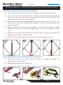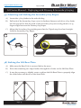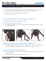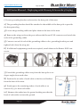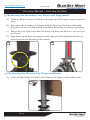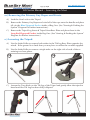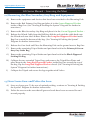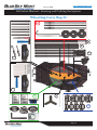
1
[email protected] AL3 Lift Series Manual Do Not Duplicate, Alter, or Copy Without the Express Written Consent of BlueSky Mast, Inc. Copyright 2012 Allendale LLC All Rights Reserved Rev: 09042012 www.BlueSkyMast.com 877-411-6278 Lift Series Manual - Disclaimers and Warranties DISCLAIMER OF WARRANTIES AND LIABILITY DO NOT ATTEMPT TO DEPLOY THIS MAST IF YOU ARE NOT EXPERIENCED IN SIMILAR DEVICES You are responsible for your own safety and survival and that of those persons around the mast. This manual is to be used as an aid and only to be used at your own risk. Nothing will replace good sound judgment when deploying the mast. The information provided in this manual should be used as a guideline and not absolute fact. Many variables are involved in deploying a mast system such as weather, soil conditions, guying distances, cantilevered payloads, surrounding obstacles, accuracy and precision of guying, etc. BLUESKY MAST, INC. MAKES NO WARRANTIES REGARDING THE GOODS, EXPRESS OR IMPLIED, INCLUDING WARRANTY OF MERCHANTABILITY OR WARRANTY OF FITNESS FOR A PARTICULAR PURPOSE. BUYER MAKES NO RELIANCE ON ANY REPRESENTATION OR DOCUMENTATION OF BLUESKY MAST, INC. , EXPRESS OR IMPLIED, WITH REGARD TO THE GOODS . BLUESKY MAST, INC. SELLS THE GOODS TO BUYER ON CONDITION THAT BLUESKY MAST, INC. WILL HAVE NO LIABILITY OF ANY KIND AS A RESULT OF THE SALE. BUYER AGREES THAT BLUESKY MAST, INC. SHALL HAVE NO LIABILITY FOR DAMAGES OF ANY KIND, WHETHER DIRECT, INCIDENTAL OR CONSEQUENTIAL DAMAGES, INCLUDING INJURIES OR DEATH TO PERSONS OR PROPERTY, TO BUYER, ITS EMPLOYEES, CUSTOMERS OR AGENTS, AS A RESULT OF THE SALE. BUYER ALSO AGREES TO HOLD BLUESKY MAST, INC. HARMLESS FROM ANY CLAIMS BUYER, OR ANY THIRD PARTY, MAY HAVE AS A RESULT OF BUYER’S USE OF THE GOODS. BUYER HAS READ THIS DISCLAIMER AND AGREES WITH ITS TERMS IN CONSIDERATION OF RECEIVING THE GOODS. REPORTING ERRORS AND RECOMMENDING IMPROVEMENTS If you find any mistakes or you can help improve this material, please contact BlueSky Mast via US Mail at: BlueSky Mast Inc 1515 Gunn Hwy Odessa, FL 33556 USA Cage Code: 3JWX5 Or Phone: 877-411-6278 International: 718-802-3266 Fax: 866-411-6278 email: [email protected] DUNS Number: 137469404 We will send you a reply concerning incorporating your suggestions. Thank You. Page 2 [email protected] 877-411-6278 Lift Series Manual - Disclaimers and Warranties LIMITED TWELVE MONTH WARRANTY This BLUESKY MAST, INC. equipment is warranted to be free from defects in material and workmanship under normal use and service. BLUESKY MAST, INC. shall repair or replace defective equipment, at no charge, or at its option, refund the purchase price, if the equipment is returned to BLUESKY MAST,INC. not more than twelve (12) months after shipment. Removal or reinstallation of equipment and its transportation shall not be at the cost of BLUESKY MAST, INC. except BLUESKY MAST, INC. shall return repaired or replaced equipment freight prepaid to a continental United States address. This Warranty shall not apply to equipment which has been repaired or altered in any way so as to affect its stability or durability, or which has been subject to misuse, negligence or accident. This Warranty does not cover equipment which has been impaired by severe weather conditions such as excessive wind, ice, storms, lightning, or other natural occurrences over which BLUESKY MAST, INC. has no control, and this Warranty shall not apply to equipment which has been operated or installed other than in accordance with the instructions furnished by BLUESKY MAST, INC. Products are manufactured from anodized aluminum in various colors. Color fading and varying shades of color will inevitably occur with exposure to sunlight and environmental conditions and is not considered a defect in the material or product Claimants under this Warranty shall present their claims along with the defective equipment to BLUESKY MAST, INC. immediately upon failure. Noncompliance with any part of this claim procedure may invalidate this warranty in whole or in part. This warranty is expressly in lieu of all other agreements and warranties, any implied warranty of merchantability or fitness for a particular purpose is limited in duration to the duration of this warranty. BLUESKY MAST, INC. Neither assumes nor authorizes any representative or other person to assume for it any other liability in connection with the equipment delivered or provided. In no event shall BLUESKY MAST, INC. Be liable for any loss of profits, loss of use, interruption of business, or indirect, special or consequential damages of any kind. In no event shall BLUESKY MAST, INC. be liable for damages in an amount greater than the purchase price of the equipment. Some states do not allow limitations on how long an implied warranty lasts, or allow the exclusion or limitation of incidental or consequential damages, so the above limitations or exclusions may not apply to you. Page 3 877-411-6278 www.BlueSkyMast.com Lift Series Manual - Safety Warnings IMPORTANT SAFETY PRECAUTIONS Part I: Power Lines, Lightning and Grounding LOOK UP AND LIVE! Before erecting the mast, check for overhead power lines. Never deploy this mast where there is any possibility of direct or indirect contact with a power line. Keep the mast a distance equal to or greater than twice its height away from power lines. This will ensure that the Antenna, masts, guy ropes or cables will not contact power if it falls either during installation or later. Any person touching any part of a mast or even standing near a mast that contacts a power line can be seriously injured or killed. BEWARE OF UNDERGROUND POWER LINES! Ground stakes might penetrate underground power lines. Before deploying any ground stakes, be sure to check the area for warnings of buried cables and contact your local power company to verify. Any person touching any part of a mast or even standing near a mast that contacts a power line can be seriously injured or killed. Keep guy ropes away from power lines to eliminate the possibility of a power line falling on the guy rope. Never touch a mast or structure that you suspect may be accidentally energized electrically. Never work with a mast or related structure during electrical storm activity. Contrary to popular belief, most lightning injuries and damage do not come from direct lightning strikes. There are several ways that lightning can injure you: “Step Potential” is potentially hazardous voltage that can exist on the ground like stepping on a live wire. This results from electrical energy diverted into the ground from lightning striking nearby. It is the most common injury causing lightning effect. Flashover is when lightning strikes a nearby object and then jumps to another nearby object. This is usually what injures people standing under trees in an electrical storm. Do not stand near the mast, deploy or retract the mast during electrical storm activity. Always ground the mast. Page 4 [email protected] 877-411-6278 Lift Series Manual - Safety Warnings IMPORTANT SAFETY PRECAUTIONS Part II: Guy Ropes and Fasteners Inspect all guy ropes and fasteners for wear or damage before use. Serious injury or death may occur if a guy rope failure causes a mast to fall. Mark guy ropes clearly to prevent personnel from tripping over them. Personnel who trip may suffer injury and may also pull up a guy rope and cause the mast to fall. Monitor the tension of the guy ropes to ensure proper tension. Ensure that stakes and anchors are secure in the ground before attaching guy ropes. Use extra caution when anchoring guy ropes, especially in sandy or loose soil. Never fasten a guy rope over a sharp edge or in a manner that causes abrasion. This may cause guy rope failure. Pad any contacting surfaces if necessary. Do not install guy ropes across roadways or other paths of travel. Always clearly mark guy ropes. Ensure guy ropes are clear of branches and other obstructions. Use only authorized parts. Unapproved substitutes may not be strong enough for the equipment. Periodically inspect the mast to ensure that it remains structurally sound and properly installed. Never overload the mast or structure. Use ONLY the equipment and accessories in proper quantities as described by the manufacture specifications. Do not use unauthorized equipment or modifications. BE CAUTIOUS of ice that may form on the antenna/mast. The area around the antenna/mast should be marked and roped off to avoid falling ice. Special care must be taken when retracting the mast or structure to avoid falling ice. Use additional guy ropes for the mast, if heavy ice loading or wind is expected or anticipated. Ensure that the wind speed is not excessive during deployment/retraction operations. Maximum safe wind speeds are available from manufacturer for your specific mast. Page 5 877-411-6278 www.BlueSkyMast.com Lift Series Manual - Safety Warnings IMPORTANT SAFETY PRECAUTIONS Part III: Wind Conditions BlueSky Mast recommends that you do not to attempt to actively deploy in winds that exceed 10 mph with Novice Users, 15 mph with Intermediate Users and 20 mph with Expert Users. During windy conditions it will be necessary to incrementally guy the mast as it is being deployed. Incremental Guying will add time to the deployment but increase the protection of personnel and equipment. USE THE CHART BELOW TO HELP DETERMINE WIND SPEED VISUAL KM/H MPH OBSERVATIONS DEPLOYMENT CONDITIONS Smoke Rises Vertically <1 <1 Safe Wind Direction Shown by Smoke 1-6 1-3 Safe Wind Felt on Face, Leaves Rustle 7-12 4-7 Safe Leaves & Twigs in Constant Motion, Wind Extends Light Flag 13-18 8-11 Use Caution Dust and Loose Paper Blown Freely, Small Branched Move 19-26 12-15 Use Caution Small Trees Begin to Sway 27-35 16-22 Dangerous Conditions Large Branches in Motion, Wind Whistles Through Wires 36-44 Whole Trees in Motion 45-55 Dangerous 23-27 Conditions Dangerous 28-34 Conditions Page 6 [email protected] 877-411-6278 Lift Series Manual - Loading and Guying Tutorial Deployable Payload A mast installation can be exposed to several types of loads. The physical weight of the instrument and its attachments is referred to as the payload. The mast can support much more weight when properly guyed and stabilized but BlueSky Masts will only recommend payloads that are safe to carry during the deployment process and we call this the deployable load. The remaining reserve load capacity represents the margin designed to absorb any subsequent environmental load that the mast may encounter. The primary environmental load on a mast is wind load. The payload capacity on a BlueSky Mast is governed by the installer’s ability to safely elevate the payload to the desired height. As poles are inserted into the tripod and the mast begins to climb, the mast tip has a tendency to lean off-center and away from its position of greatest strength. An iterative process of incremental guying and mast pole elevation may be required to successfully deploy the mast. For best results, please limit your deployment to the height and payload combinations given in the table below. MODEL Deployable Load (lbs.) Wind Load (Primary and Secondary Guying) 3 Meter (10.5 Feet) 180 lbs. 90 MPH 4 Meter (14 Feet) 170 lbs. 90 MPH 5 Meter (17.5 Feet) 160 lbs. 90 MPH 6 Meter (21 Feet) 155 lbs. 90 MPH 7 Meter (24.5 Feet) 150 lbs. 90 MPH 8 Meter (28 Feet) 145 lbs. 90 MPH 10 Meter (31.5 Feet) 125 lbs. 90 MPH 11 Meter (35 Feet) 115 lbs. 90 MPH 12 Meter (38.5 Feet) 105 lbs. 90 MPH 13 Meter (42 Feet) 95 lbs. 90 MPH 14 Meter (45.5 Feet) 85 lbs. 90 MPH 15 Meter (49 Feet) 75 lbs. 90 MPH Page 7 877-411-6278 www.BlueSkyMast.com Lift Series Manual - Loading and Guying Tutorial Wind Effects When wind blows on a mast and its instruments, the guys restrict the top of the mast and its instruments from moving off center. The mast’s reaction to wind will put tension in the guy line and force the top of the mast downward in compression, the amount of which will vary depending on the anchor distance as described below. The size and shape of the instruments determine the amount of force they produce in any given wind condition. Don’t forget that the mast itself is a surface area exposed to the wind and its wind load will need to be added to the instrument wind load to get the total wind load on the system. The mast wind loads are given in the table at the end of this section and clearly show the benefits of Secondary Guying. Guying Guy lines are used to maintain the position of the top of the mast directly over the center of the tripod. This is its position of greatest strength, which will maximize the load carrying capacity of the mast in terms of payload as well as wind survivability. When no wind is present, the guy lines remain critical to stabilize the top of the mast and to keep the instrument mounts level. Page 8 [email protected] 877-411-6278 Lift Series Manual - Loading and Guying Tutorial Anchor Radius Ideal guying is set with an anchor radius of 80% of the mast height. Many applications of mast deployments are not able to afford an installation footprint of this size and installers may find it more convenient to place the guy anchors much closer to the mast as shown in the figure to the right. BlueSky Mast does not recommend configurations utilizing less than 80% guy radius, but if your site dictates that you must deviate from the recommended configuration it is imperative that the installer is aware of the effects of the reduced anchor radius and its effect on total payload capacity and wind loading. The angle of pull on the guy line relative to the anchor radius may produce a lever effect increasing the mast compression due to wind loading by a factor of 5 ! The table at left shows the affect the anchor radius has on the multiplying factors of compressive loads produced on the mast by a horizontal wind force. Below are examples of various anchor radii. 80% Page 9 30% 877-411-6278 www.BlueSkyMast.com Lift Series Manual - Loading and Guying Tutorial Primary and Secondary Guy Placement BlueSky utilizes a 4 guy configuration to help minimize the affect wind loading has on the mast. The primary guys are always deployed from the top of the mast and extend out at a 90 degree angle from each other. The secondary guys are deployed halfway down the mast between the top of the tripod and the primary guys. They are also deployed at 90 degrees of each other and 45 degrees of the primary guy ropes. The primary and secondary guys are always deployed at the same distance or anchor radius from the base of the mast. Guying Distance From the Base of the Mast If you are unable to utilize the 80% rule then refer to the load characteristics of your mast in the tables following this section to understand the impact to the payload capacity and wind loading of your mast. Page 10 [email protected] 877-411-6278 Lift Series Manual - Load Tables 15 Meter System - Specifications 14 Meter System - Specifications Page 11 877-411-6278 www.BlueSkyMast.com Lift Series Manual - Load Tables 13 Meter System - Specifications 12 Meter System - Specifications Page 12 [email protected] 877-411-6278 Lift Series Manual - Load Tables 11 Meter System - Specifications 10 Meter System - Specifications Page 13 877-411-6278 www.BlueSkyMast.com Lift Series Manual - Load Tables 8 Meter System - Specifications 7 Meter System - Specifications Page 14 [email protected] 877-411-6278 Lift Series Manual - Load Tables 6 Meter System - Specifications 5 Meter System - Specifications Page 15 877-411-6278 www.BlueSkyMast.com Lift Series Manual - Load Tables 4 Meter System - Specifications 3 Meter System - Specifications Page 16 [email protected] 877-411-6278 Anatomy of an AL3 Tripod Cross Bar Tricollar w/ Rollers Winch Turn Knob & Threaded Coupling Tripod Leg Swivel Tripod Base Plate Ball Stop Holder Bubble Levels x 3 Page 17 Cam Lock 877-411-6278 www.BlueSkyMast.com Lift Series Manual - Packing and Parts Break Down Page 18 [email protected] 877-411-6278 Lift Series Manual - Packing and Parts Break Down Wheeling Carry Bag #2 (15 Meters) Page 19 877-411-6278 www.BlueSkyMast.com Lift Series Manual - Deploying with Primary & Secondary Guying Deploying the Mast System With Primary and Secondary Guying Expert Users - 3 People - 30 Minutes Novice Users - 5 People - 45 Minutes When raising and lowering the mast it is highly recommended that a person be dedicated to each primary guy rope until the mast no longer requires incremental guying. This number can be reduced if experienced personnel are present. Page 20 [email protected] 877-411-6278 Lift Series Manual - Deploying with Primary & Secondary Guying Page 21 www.BlueSkyMast.com 877-411-6278 Lift Series Manual - Deploying with Primary & Secondary Guying 1) Inspecting the Site Before Deployment. A) Make sure the ground where you are deploying is level and clear of debris. B) Make sure the ground is capable of holding the tripod stakes and guy stakes. C) Make sure there is enough room to extend your guy ropes out to the full length based on your deployment height. D) SAFETY: Make sure there are no overhead wires, buried power lines, or an unexploded ordinance. 2) Unpacking Bag One. A) Remove Tripod, Mounting Pole, Lift Base Plate, Strut Base Plate, Stake Kit Bag and Guy Kit Bag from Bag One and set next to Bag One. B) Leave the Base Pole in Bag One. 2A 2B Lift Base Plate Stake Kit Bag Guy Kit Bag Mounting Pole Tripod Strut Base Plate Wheeling Carry Bag 1 3) Setting Up and Orienting the Tripod. A) Check to make sure the ground is level and clear of debris. B) Locate the Tripod (from Bag One) Page 22 [email protected] 877-411-6278 Lift Series Manual - Deploying with Primary & Secondary Guying 3) Setting Up and Orienting the Tripod. (continued..) C) Stand the tripod up on the ground with the Tilt Leg (opposite the winch) facing in the same direction that you want your equipment to point, release the Velcro Strap. D) Unfold the tripod legs and lock them into place. E) SAFETY: Verify the cross bars on each tripod leg are fully deployed and locked into position by pushing down on them. 3D 3C 3E 4) Attaching the Tripod Base Plates. A) Attach the tripod base plates (located in the Long Red Zippered Pocket in Bag One) to the bottom of each tripod leg. 4A 4A Page 23 www.BlueSkyMast.com 877-411-6278 Lift Series Manual - Deploying with Primary & Secondary Guying 5) Extending the Two Tripod Legs. A) One at a time, fully extend the two tripod legs adjacent to the winch by loosening the turn knobs on the tripod legs. DO NOT EXTEND the Tilt Leg, opposite the winch. 5A B) Once fully extended, lock them in place using the turn knobs making sure to orient the Strut Couplings towards the center of the mast. C) Drive a SINGLE tripod stake (located in the black stake kit bag) into the LEFT SIDE of each of the two base plates on the extended legs only. 5B 5C 5C Page 24 [email protected] 877-411-6278 Lift Series Manual - Deploying with Primary & Secondary Guying 6) Inserting the Mounting Pole. A) Release the Cam Lock on the bottom of the tripod. B) Locate the Mounting Pole on the ground next to Bag One. (The only pole without a silver insert) C) Insert it into the top of the tripod with the castle cut on the bottom of the pole until the first hole on the Mounting Pole is visible below the Cam Lock, then lock it into place using the Cam Lock. 6A 6C 6C 7) Cam Lock Maintenance. A) If at any point the mast begins to slip while the Cam Lock is engaged, use the wrench provided with the system to make adjustments. B) If slipping occurs after center mast poles have been deployed, lower the mast so that it contacts the ground. C) Tighten the nut on the Cam Lock a quarter of a turn until slipping no longer occurs. 7C 7C Page 25 www.BlueSkyMast.com 877-411-6278 Lift Series Manual - Deploying with Primary & Secondary Guying 8) Adding the Primary and Secondary Guy Ring. A) Locate the Blue Secondary Guy Ring (located in the Green Zippered Pocket of Bag One). B) 8A Release the Cam Lock on the Blue Secondary Guy Ring and slide it over the top of the mounting pole until it rests on top of the tripod. DO NOT lock it into place at this time. 8B C) Locate the Red Primary Guy Ring (located in the Green Zippered Pocket of Bag One). D) Remove the push pin and slide it over the top of the Mounting Pole until it rest on top of the Blue Secondary Guy Ring. DO NOT pin on the Red Primary Guy Ring at this time. 8C 8D Page 26 [email protected] 877-411-6278 Lift Series Manual - Deploying with Primary & Secondary Guying 9) Attaching Your Equipment to the Mounting Pole. A) Attach your equipment to the Mounting Pole. B) Properly adjust and secure your equipment and connect any cables at this time. C) SAFETY: Always secure loose cables to the Center Mast during deployment with Velcro or some form of cable management to reduce strain on the cables and prevent damage to the connections. Loose cables can also cause the mast to lean to one side and affect performance and safety. 9A 10) Raising the Tilt Leg. A) Loosen the Turn Knob on the Tilt Leg. B) Raise the tripod then extend the Tilt Leg fully. C) Tighten the Turn Knob making sure to orient the Strut Coupling towards the center of the mast at the same time. 10A 10B Page 27 10B www.BlueSkyMast.com 877-411-6278 Lift Series Manual - Deploying with Primary & Secondary Guying 11) Leveling the Tripod. A) Locate the 3 Bubble Levels on the Tripod. B) If any of the bubbles fall beyond the level lines, one at a time, loosen the turn knob on the leg and adjust the length as needed to make the tripod level. Tighten the turn knobs when finished. C) When adjusting the Tripod Legs, make sure that the Strut Couplings are facing toward the center of the tripod. D) SAFETY: CHECK THE BUBBLE LEVELS OFTEN! Improper leveling can result in excessive leaning which can damage the system and can cause serious bodily harm. 11A 11C 11A 12) Securing the Tripod. A) Make sure all Tripod Base Plates are level and flat on the ground. B) Drive tripod stakes (located in the Black Stake Kit Bag) into the remaining holes on all three tripod leg base plates. 12A 12B Page 28 [email protected] 877-411-6278 Lift Series Manual - Deploying with Primary & Secondary Guying 13) Attaching the Winch Handle. A) Locate the Winch Handle (located in the Blue Zippered Pocket of Bag One). B) Pull the Quick Release Pin on the front of the Winch. Slide the Winch Handle into the slot. Release the pin and lock the handle into place. 13A 13B 13C 14) Attaching the Lift Base Plate. A) Locate the Lift Base Plate. B) Insert it into the bottom of the Mounting Pole. C) Align the Lift Base Plate so that the rollers on the plate are in line with the Winch and the Tilt Leg. 14B 14A Page 29 14C www.BlueSkyMast.com 877-411-6278 Lift Series Manual - Deploying with Primary & Secondary Guying 15) Attaching and Securing the Winch Cable. A) Turn the Winch Handle counter-clockwise paying out about three feet of cable. B) Insure the cable hangs freely from the bottom left side of the winch. C) Pass the end of the cable with the Ball Stop through the bottom of the two rollers on the Lift Base Plate. 15B 15C D) Locate the Ball Stop Holder located on the bottom of the Tripod opposite the Winch E) Secure the Ball Stop by pulling the pin on the Ball Stop Holder and guide the Ball Stop into place. F) SAFETY: After releasing the pull pin on the Ball Stop Holder, tug on the cable to make sure it is securely in place. G) Remove the slack in the cable by cranking the winch handle clockwise until the Lift Base Plate is seated securely in the bottom of the Mounting Pole. 15D 15E 15G Page 30 [email protected] 877-411-6278 Lift Series Manual - Deploying with Primary & Secondary Guying 16) Deploying and Aligning the Strut Plate. A) Locate the Strut Base Plate. B) Place the Strut Base Plate on the ground centered directly below the Lift Base Plate. C) Rotate the Strut Base Plate until the Strut Base Plate receivers line up with the Strut Couplings on the tripod legs. 16A 16C 17) Attaching the Leg Struts. A) Locate the 3 Leg Struts (in the Long Red Zippered Pocket of Bag One) B) Attach the Leg Struts to the Strut Couplings located at the center of each Tripod leg next to the turn knob. C) Screw the struts all the way down, then back off a partial turn until the Turn Knobs on the Tripod Struts are facing directly up. 17B 17C 17C UP Page 31 www.BlueSkyMast.com 877-411-6278 Lift Series Manual - Deploying with Primary & Secondary Guying 17) Attaching the Leg Struts. (continued...) D) One at a time, insert the Tripod Struts into each receiver on the Strut Base Plate by loosening the Turn Knob on the Leg Strut and extending the inside strut. E) It may be necessary to also rotate the tripod legs slightly to properly align the Leg Struts. F) Be sure that the struts are fully inserted into the receivers on the Strut Base Plate. G) The holes on the strut and the receiver will line up if inserted correctly. Insert the hitch pin and secure it. 17D 17F 17G 18) Leveling the Tripod. A) Locate the 3 Bubble Levels on the Tripod. B) If any of the bubbles fall beyond the level lines, one at a time, loosen the turn knob on the leg and adjust the length as needed to make the tripod level. C) Fully tighten both the Tripod Leg Turn Knobs and the Struts Turn Knobs. D) SAFETY: Never adjust the Leg Strut Turn Knobs or Leg Turn Knobs during or after deployment of the Center Mast Poles. 18A 18A 18B Page 32 [email protected] 877-411-6278 Lift Series Manual - Deploying with Primary & Secondary Guying 19) Securing the Strut Base Plate to the Ground. A) Locate the Strut Base Plate Stake that has the flat red head (in the Stake Kit Bag) B) Drive the stake into the hole in the center of the Strut Base Plate being careful not to place your head or body below the Lift Base Plate. C) SAFETY: Never place your head or body below the bottom of the Lift Base Plate when it is in the air. 19A 19B 20) Lifting the Mounting Pole. A) Make sure that the cable is taut and the Lift Base Plate is secure in the bottom of the Mounting Pole. B) Release the Cam Lock on the bottom of the tripod. C) Raise the Mounting Pole by cranking the winch handle clockwise until the bottom of the Mounting Pole is within one inch of the bottom of the tripod. D) Secure the Mounting Pole by locking the Cam Lock on the tripod. E) SAFETY: When raising the poles, make sure there is always at most one inch of the pole visible beneath the bottom of the tripod before securing the Cam Lock. 20C 20B 20D 1” Page 33 www.BlueSkyMast.com 877-411-6278 Lift Series Manual - Deploying with Primary & Secondary Guying 21) Securing the Primary Guy Ring. A) Pin the Red Primary Guy Ring to the Mounting Pole below your equipment making sure to allow enough room for the Primary Guys to be deployed later without interference. 21A 21A 22) Primary Guying - Locating the Primary Guy Ropes and Stakes. A) Locate the four Primary Guy Ropes with the Dual Stake Plates attached (in the Green Zippered Pocket of Bag One). B) Locate the 8 Guy Stakes (in the Black Stake Kit Bag) Page 34 [email protected] 877-411-6278 Lift Series Manual - Deploying with Primary & Secondary Guying 23) Primary Guying - Deploying the 1st Primary Guy Rope. A) Attach the red stainless steel clip on the free end of the 1st Primary Guy Rope to the round hole on the Red Primary Guy Ring. B) Walk away from the mast while unwinding the guy rope from the handle. C) Take one normal walking step for every meter of height of the mast and stop. (Example: 15 Meter Mast equals 15 steps or paces.) Do not use exaggerated steps, the total distance of each step should equal 2.5 feet or 30 inches. 23A 23B 23C D) Unwind the remaining guy rope off the handle and drive two stakes through the Dual Stake Plates. 23D 23D Page 35 877-411-6278 www.BlueSkyMast.com Lift Series Manual - Deploying with Primary & Secondary Guying 24) Primary Guying - Deploying the 1st Primary Guy Rope . (continued...) D) Make sure the rope is properly aligned on the handle in the unlocked position. E) Slide the handle toward the mast approximately 7 feet. This will take up some slack in the guy rope and will prepare you for the steps needed for Incremental Guying. 24D 24E t 7 Fee Page 36 [email protected] 877-411-6278 Lift Series Manual - Deploying with Primary & Secondary Guying 25) Primary Guying - Deploying the 2nd Primary Guy Rope. A) Attach the red stainless steel clip on the free end of the 2nd Primary Guy Rope to the square hole opposite the round hole on the Red Primary Guy Ring. B) Walk away from the mast (directly opposite of the 1st Primary Guy) while unwinding the guy rope from the handle. C) Take one normal step for every meter of height of the mast and stop. (Example: 15 Meter Mast equals 15 steps or paces.) D) Unwind the remaining guy rope off the handle and drive two stakes through the Dual Stake Plates. E) Slide the handle toward the mast approximately 7 feet 25B 25A 2nd 1st 26) Primary Guying - Deploying the Remaining Primary Guy Ropes. A) Attach the stainless steel clip on the free end of the 3rd and 4th Primary Guy Ropes to the remaining square holes on the Primary Guy Ring. B) 25C Repeat the process outlined above until all guy ropes have been deployed. C) When finished, the Primary Ropes should be deployed 90 degrees from each other. Page 37 26C www.BlueSkyMast.com 877-411-6278 Lift Series Manual - Deploying with Primary & Secondary Guying 27) Lowering the Lift Base Plate to the Ground. A) SAFETY: Always make sure the Cam Lock is engaged before lowering the Lift Base Plate. B) Slowly begin lowering the Lift Base Plate by turning the winch handle counter clockwise making sure that the Center Mast Poles do not begin to move. C) SAFETY: If the mast begins to slipping occurs check that the Cam Lock is engaged. If it is engaged, refer to the “Cam Lock Maintenance” section of the manual. D) Continue lowering the Lift Base Plate until it rest flat on the ground. 27D 27B 28) Inserting the First Center Mast Pole. A) Locate a Center Mast Pole (with the silver insert) in Bag Two and insert the bottom of the Center Mast Pole onto the tapered cone of the Lift Base Plate. C) THIS IS A ONE PERSON OPERATION - Slowly crank the winch handle with one hand while using the other hand to gently guide the silver insert of the Center Mast Pole into the bottom of the Mounting Pole. D) Make sure the poles nest together fully and no silver is showing in the seam. You may need to twist the Center Mast Pole slightly to make sure the castle cuts nest together properly. 28B 28C 28D Page 38 [email protected] 877-411-6278 Lift Series Manual - Deploying with Primary & Secondary Guying 29) Lifting the Center Mast Pole. A) Make sure that the cable is taut and straight. If the cable has become slightly twisted then tap the Lift System Base Plate lightly with your foot to straighten out the cable. 29A B) Release the Cam Lock on the bottom of the tripod. C) Raise the Center Mast Pole by cranking the winch handle clockwise until the bottom of the Center Mast Pole is within one inch of the bottom of the tripod. D) Secure the Center Mast Pole by locking the Cam Lock on the tripod. E) SAFETY: When raising the poles, make sure there is always at most one inch of the pole visible beneath the bottom of the tripod before securing the Cam Lock. F) Repeat this process of adding Center Mast Poles until it is time to engage the Blue Secondary Guy Ring. 29B 29C 1” Page 39 www.BlueSkyMast.com 877-411-6278 Lift Series Manual - Deploying with Primary & Secondary Guying 30) Secondary Guying - Securing the Secondary Guy Ring. A) When you have deployed the mast half way, stop and lock the Cam Lock on the bottom of the tripod. B) Locate the Blue Secondary Guy Ring on top of the tripod and lock down the Cam Lock on the Secondary Guy Ring. C) SAFETY: Make sure that the Cam Lock is fully locked and that the safety is covering the Cam Lock Lever. This will prevent a guy rope from accidentally unlocking the Blue Secondary Guy Ring during deployment. 30A 30B 30C 31) Secondary Guying - Deploying the Secondary Guy Ropes. A) Locate the four Secondary Guy Ropes in the zippered pocket of Bag One. B) 31A Attach the blue stainless steel clip on the free end of the 1st Secondary Guy Rope to the round hole on the Blue Secondary Guy Ring. 31B Page 40 [email protected] 877-411-6278 Lift Series Manual - Deploying with Primary & Secondary Guying 32) Secondary Guying - Deploying the Secondary Guy Ropes. C) Walk away from the mast while unwinding all of the guy rope from the handle. Place the 1st Secondary Guy Rope on the ground in between two of the Primary Guy Ropes so that it is at a 45 degree angle from the Primary Guy Ropes. DO NOT stake the Secondary Guy Rope at this time. D) Repeat the Process for the remaining 3 Secondary Guy Ropes. DO NOT stake the Secondary Guy Ropes, they will be adjusted and staked at the end of the deployment. Constantly check on the deployed guy ropes as they can get tangled in equipment. 32C 32D Page 41 877-411-6278 www.BlueSkyMast.com Lift Series Manual - Deploying with Primary & Secondary Guying 33) Continue Lifting the Center Mast Poles Until Incremental Guying is Required. A) Continue raising the center mast poles with same procedure until the Primary Guy Ropes go taut or the mast begins to lean causing the Bubble Levels to indicate that the mast is no longer level and Incremental Guying is required. B) When the mast begins to lean it will be necessary to adjust the Primary Guy Ropes for the rest of the deployment to maintain proper leveling and a straight mast. Incremental Guying - Why is it Important? Heavy loads or windy conditions can exert extra force on the center mast poles during deployment causing them to bind in the tripod and create potentially unsafe conditions. Incremental Guying is used when the mast begins to lean and is no longer straight and perpendicular which can cause binding in the tripod during deployment. Binding creates friction in the tripod making the poles harder to crank up in the air and puts unnecessary strain on the winch. Incremental guying may be required when less than two people are available to hold the primary or secondary guy ropes during deployment with heavy loads or high winds. Excessive leaning during deployment is an indicator that incremental guying is required. When these conditions exist, it will be necessary to incrementally guy the mast during deployment before reaching the desired height. Incremental guying will add time to the deployment but will ensure the safety of both personnel and equipment Be sure when adjusting the amount of tension on the guy ropes not to over tighten the guy ropes. This puts significant downward pressure on the mast. See the diagram below for reference on how guy ropes and the mast should look when correctly deployed. Page 42 [email protected] 877-411-6278 Lift Series Manual - Deploying with Primary & Secondary Guying 34) Utilizing Incremental Guying. A) Once the mast begins to lean or the Primary Guy Ropes go taut, then stop cranking the winch and Lock the Cam Lock B) Start with the Guy Rope opposite the direction the mast is leaning. C) Pull on the knotted end of the guy handle until you have removed enough slack in the rope to allow only one center mast pole to be inserted. D) Tie a slip knot in the slack to prevent the line from sliding back through the hole on the guy handle E) Slide the Primary Guy Rope Handle toward the mast to tighten the rope and straighten the mast. F) It may be necessary to have another person at a guy rope 90 degrees away, or a man on each guy rope to instruct whether a guy rope needs to be adjusted. G) Adjust all of the Primary Guy Ropes until the mast is straight and perpendicular. H) Then let out the guy ropes one full arms length to allow enough slack in the line for the mast to be raised. I) Continue raising poles until the mast has been deployed to full height and it is time to insert the Base Pole. Repeat incremental guying steps as needed. 34C 34D 34E 35) Deploying the Base Pole. A) Locate the Base Pole. (in Bag One). It looks like a Center Mast Pole with holes on the sides and is labeled “Base Pole”. BASE POLE Page 43 www.BlueSkyMast.com 877-411-6278 Lift Series Manual - Deploying with Primary & Secondary Guying 35) Deploying the Base Pole. (Continued) B) Insert the bottom of the Base Pole into the tapered cone of the Lift Base Plate. C) THIS IS A ONE PERSON OPERATION - Slowly crank the winch handle with one hand while using the other hand to gently guide the silver insert of the Base Pole into the bottom of the last Center Mast Pole. D) Make sure the poles nest together fully and no silver is showing in the seam. You made need to twist the Center Mast Pole slightly to make sure the castle cuts nest together properly. E) Make sure that the cable is taut and straight. If the cable has become slightly twisted then tap the Lift Base Plate lightly with your foot to straighten out the cable. F) Release the Cam Lock and SLOWLY lower the Base Pole to the ground until the Lift Base Plate rests firmly on the Strut Plate. G) SAFETY: If the base pole & mast do not lower, adjust the guy ropes. 35B 35C 35F 36) Locking & Securing the Primary Guy Ropes. A) Adjust the Primary Guy Ropes until the mast is completely straight and perpendicular to the ground. B) Pull a small amount of slack in the line. C) Grab the rope and wrap it around the rope lock to secure the Primary Guy Ropes. 36B 36C 36C Page 44 [email protected] 877-411-6278 Lift Series Manual - Deploying with Primary & Secondary Guying 37) Adjusting and Staking the Secondary Guy Ropes. A) Locate the 4 Guy Stakes in the stake kit bag. B) Pull each of the Secondary Guys out to its furthest distance and drive a Guy Stake into the ground so that the each of the Secondary Guys are evenly placed at a 45 degree angle between the Primary Guy Ropes. C) Adjust the Secondary Guys making sure that the Tripod stays level and straight. Lock the Secondary Guy Ropes. 37B 37C 38) Staking the Lift Base Plate. A) Make sure the Base Pole is centered below the mast. B) Drive the remaining two tripod stakes through the 2 holes on the Lift Base Plate. C) It may be necessary to slightly rotate or adjust the Lift Base Plate to properly align the stake holes with those on the Strut Plate. 38B Page 45 38C www.BlueSkyMast.com 877-411-6278 Lift Series Manual - Deploying with Primary & Secondary Guying 39) Align and Secure Equipment. A) If you have directional equipment on top of the mast that you need to align, then release the Cam Lock on the Tripod and rotate the mast as needed. B) Lock the Cam Lock on the tripod when complete. C) Secure any Loose Cables 40) Secure the Winch to prevent tampering. (Optional) A) Remove the ball stop from the ball stop holder. B) Wind the free cable onto the winch C) The Winch Handle can be removed and stowed back in the Bag to prevent tampering if left unattended. 40A 40B 40C 41) Deploy the Surface Wire Grounding Kit. (Optional) A) The BlueSky Surface Wire Grounding Kit (additional accessory) can be deployed at this time if available when lightning or static discharge is a safety concern. 42) Stow the Bags and Secure the Area. A) Police the area for any loose tools or equipment that may have been left in the field during deployment. B) Stow the bags in a safe place for easy retrieval. Page 46 [email protected] 877-411-6278 Lift Series Manual - Deploying with Primary & Secondary Guying 1) Locate grounding bracket and attach to the base pole of the mast. 2) The grounding bracket should be attached to the middle of the base pole to provide the best grounding. 3) Locate the grounding cables and place them at the base of the mast. 4) Remove the wing nut from the post without the Bronze ECLE connector and attach the ends of the grounding cables. 5) Connect one end of each of the grounding cables to the grounding bracket post and tighten back down the wing nut. 6) If additional equipment grounds are required, attach them to the Bronze ECLE connector. 7) Extend the grounding cables away from the base pole at 120 degree angles from each other. 8) Position the 1st stake of each cable at the free end furthest from the base of the mast. 9) Evenly space the remaining stakes of each cable at an interval of 4.5 ft. from each other. 10) Hammer the stakes into the ground making sure that the head of each stake contacts the ground. Page 47 www.BlueSkyMast.com 877-411-6278 Lift Series Manual - Lowering the Mast Lowering the Mast System With Primary and Secondary Guying Expert Users - 3 People - 20 Minutes Novice Users - 5 People - 35 Minutes When lowering the mast it is highly recommended that a person be dedicated to each primary guy rope until the mast no longer requires incremental guying. This number can be reduced if experienced personnel are present. Page 48 [email protected] 877-411-6278 Lift Series Manual - Lowering the Mast Page 49 www.BlueSkyMast.com 877-411-6278 Lift Series Manual - Lowering the Mast 1) Reconnecting the Winch Cable. A) Replace the Winch Handle if it was removed. B) Run the cable through the Lift Base Plate. C) Secure the cable properly in the Ball Stop Holder, test by pulling on the cable to ensure a secure fit. 1A 1C 2) Removing the Lift Base Plate Stakes. A) Locate the Stake Puller ( in the Black Stake Bag) B) Remove the stakes in the Lift Base Plate utilizing the Stake Puller. C) Helpful Hit: If the ground is hard and compact, use the Stake Puller as a fulcrum and pull on one side of the stake puller allowing the other side to contact the ground providing upward leverage. 2A 2B Page 50 [email protected] 877-411-6278 Lift Series Manual - Lowering the Mast 3) Loosening the Primary and Removing the Secondary Guy Ropes. A) Unlock the Primary Guy Ropes and loosen them by sliding the Rope Stay away from the mast approx 12 inches. B) Pull the stakes attached to the Secondary Guy Ropes, unclip from the stakes and place the four stakes back in the Primary & Secondary Guy Stake Bag. 3A 3A n 12 I s che 4) Raising the Base Pole. A) Release the Cam Lock B) Raise the Base Pole approx 12 inches by SLOWLY turning the Winch Handle clockwise until there is only one inch of the bottom of the Center Mast Pole above the Base Pole visible below the bottom of the tripod. C) Lock the Cam Lock 4A 4C Page 51 www.BlueSkyMast.com 877-411-6278 Lift Series Manual - Lowering the Mast 5) Removing the Base Pole. A) SAFETY: Always make sure the Cam Lock is engaged before lowering the Lift Base Plate. B) Lower the Base Pole to the ground by SLOWLY turning the Winch Handle counter clockwise until the Lift Base Plate rests firmly on top of the Strut Base Plate. 5B 5B C) SAFETY: If the Center Mast Pole above begins to slip as you lower the Base Pole, then you have not engaged the Cam Lock fully. Lock the Cam Lock fully. D) Remove the Base Pole from the Lift Base Plate and place it on the ground next to Bag One, DO NOT put it in BAG Two. E) Raise the Lift Base Plate until it seats firmly into the bottom of the next Center Mast Pole and the cable is straight and taut. 5C 1” Page 52 [email protected] 877-411-6278 Lift Series Manual - Lowering the Mast Incremental Guying - Why is it Important when lowering the mast? Incremental Guying is MANDATORY when lowering the mast to prevent leaning during the process which can cause binding in the tripod. Binding creates friction in the tripod making the poles harder to lower and causing potential unsafe conditions. When lowering the mast it is highly recommended that a person be dedicated to each primary guy rope until the mast no longer requires incremental guying. This number can be reduced if experienced personnel are present. 6) Lowering the Mast - Removing the Next Center Mast Pole. A) Release the Cam Lock. B) SLOWLY begin lowering the Center Mast Pole by turning the Winch Handle counter clockwise no more than two revolutions per second. C) SAFETY: Incremental Guying must be utilized as necessary during this process allowing the mast to remain straight and perpendicular at all times. This will allow the mast poles to slide down through the tripod easily without binding. D) SAFETY: Make sure the cable remains taut at all times and that the Lift Base Plate stays in the bottom of the Center Mast Pole. If the Lift Base Plate should come out of the Center Mast Pole, immediately stop and lock the Cam Lever and reconnect until the cable is taut and the mast is straight before continuing. E) Lower the Center Mast Pole until at most one inch of the Center Mast Pole above it is visible below the tripod. 6B 6E Page 53 www.BlueSkyMast.com 877-411-6278 Lift Series Manual - Lowering the Mast 6) Lowering the Mast - Removing the Next Center Mast Pole . (continued...) F) Lock the Cam Lock G) Continue lowering the Center Mast Pole until the Lift Base Plate rests on the ground. H) Place the Center Mast Pole back into Bag Two. 6F I) 6G Raise the Lift Base Plate until it seats firmly into the bottom of the next Center Mast Pole and the cable is straight and taut. 6H 1” Page 54 [email protected] 877-411-6278 Lift Series Manual - Lowering the Mast 7) Straightening the Mast - Adjusting the Primary Guy Ropes. A) Tighten the Primary Guy Ropes until the mast is straight and perpendicular and not leaning. 8) Repeating the Process. A) Release the Cam Lock. B) SLOWLY begin lowering the Center Mast Pole by turning the Winch Handle counter clockwise no more than two revolutions per second. C) SAFETY: Incremental Guying must be utilized as necessary during this process allowing the mast to remain straight and perpendicular at all times. This will allow the mast poles to slide down through the tripod easily without binding. D) SAFETY: Make sure the cable remains taut at all times and that the Lift Base Plate stays in the bottom of the Center Mast Pole. If the Lift Base Plate should come out of the Center Mast Pole, immediately stop and lock the Cam Lock and reconnect until the cable is taut and the mast is straight before continuing. E) Lower the Center Mast Pole until at most one inch of the Center Mast Pole above it is visible below the tripod. 8B 8B Page 55 www.BlueSkyMast.com 877-411-6278 Lift Series Manual - Lowering the Mast 8) Repeating the Process. (continued...) F) Lock the Cam Lock G) Continue lowering the Center Mast Pole until the Lift Base Plate rest on the ground. H) Place the Center Mast Pole back into Bag Two. 8F 8G I) Raise the Lift Base Plate until it seats firmly into the bottom of the next Center Mast Pole and the cable is straight and taut. J) Repeat the process until it’s time to release the Cam Lock on the Blue Secondary Guy Ring and remove the Secondary Guy Ropes. 8I 1” Page 56 [email protected] 877-411-6278 Lift Series Manual - Lowering the Mast 9) Removing the Secondary Guy Ropes and Equipment. A) When the Blue Secondary Guy Ring reaches the top of the tripod, stop lowering the mast. B) Disconnect the Secondary Guy Ropes, wind the loose rope back onto the handle, then place the four Guy Ropes back in the Black Pull String Secondary Guy Kit Bag. C) Release the Cam Lock on the Blue Secondary Guy Ring and allow it to rest on top of the Tripod. D) Begin lowering the mast repeating the same steps until all equipment has been removed and only the Mounting Pole remains. 9C 9D 10) Removing the Primary Guy Ropes and Struts. A) Lower the Mounting Pole until the Red Primary Guy Ring is easily within reach. 10A Page 57 www.BlueSkyMast.com 877-411-6278 Lift Series Manual - Lowering the Mast 10) Removing the Primary Guy Ropes and Struts. A) Lock the Cam Lock on the Tripod B) Remove the Primary Guy Ropes and wind all of the rope onto the handle and place all 4 in the Blue Zippered Pocket inside of Bag One. (See “Stowing & Packing the System” Diagram for further instructions.) C) Remove the Tripod Leg Struts & Tripod Strut Base Plate and place them in the Long Red Zippered Pocket inside Bag One. (See “Stowing & Packing the System” Diagram for further instructions.) 11) Lowering the Tripod. A) Use the Stake Puller to remove both stakes in the Tilt Leg Base Plate opposite the winch. If the ground is to hard then you may have to utilize the crowbar supplied. B) Use the Stake Puller to remove a single stake on the right side of each of the remaining two base plates. 11A 11B C) Loosen the Turn Knob on the Tilt Leg of the Tripod and gently allow the tripod to kneel until the Tilt Leg has been fully collapsed. Page 58 [email protected] 877-411-6278 Lift Series Manual - Lowering the Mast 12) Removing the Blue Secondary Guy Ring and Equipment. A) Remove the equipment and devices that have been attached to the Mounting Pole. B) Remove the Red Primary Guy Ring and place it in the Green Zippered Pocket inside of Bag One. (See “Stowing & Packing the System” Diagram for further instructions.) C) Remove the Blue Secondary Guy Ring and place it in the Green Zippered Pocket . D) Release the Winch Cable from the Ball Stop Holder and wind the cable back onto the Winch and stow the Lift Base Plate in the Long Red Zippered Pocket inside Bag One toward the bottom of the bag. (See “Stowing & Packing the System” Diagram for further instructions.) E) Release the Cam Lock and Place the Mounting Pole on the ground next to Bag One. F) Remove the remaining Tripod Stakes and put them back in the Primary & Secondary Guy Stake Bag. G) Remove the remaining Tripod Stakes and put them back in the Black Zippered Staking Kit Bag. H) Collapse the two extended Tripod Legs and remove the Tripod Base Plates and place them in the Long Red Zippered Pocket inside Bag One toward the top of the bag. Zip the Long Red Zippered Pocket closed. (See “Stowing & Packing the System” Diagram for further instructions.) I) Collapse the Tripod and secure the legs together with Velcro. 13) Stow Loose Gear and Police the Area. A) Stow any loose gear. To be sure of optimal packing, continue to “Stowing & Packing the System” Diagram for further instructions. B) Police the area to make sure that all gear and tools have been accounted for and stowed properly. Page 59 www.BlueSkyMast.com 877-411-6278 Lift Series Manual - Stowing and Packing the System Wheeling Carry Bag #1 2 9 8 4 5 Top Bottom 6 7 3 1 Page 60 [email protected] 877-411-6278 Lift Series Manual - Stowing and Packing the System Wheeling Carry Bag #1 1) Place the (4) Primary & (4) Secondary Guy Ropes in the Blue Zippered Pocket (upper right pocket if standing at the bottom of the bag as shown in the diagram) and zip it closed. 2) Place the Tripod Leg Struts, Base Plates & Crowbar in the Long Red Zippered Pocket and zip it closed. 3) Place the Reference Pack, (AL3 Manual, Reference Sheet and a wrench) Cable Management Straps, Red Primary Guy Ring, Lift Base Plate, Blue Secondary Guy Ring and Winch Handle in the Green Zippered Pocket (bottom right pocket if standing at the bottom of the bag as shown in the diagram) and zip it closed. 4) Place the Tripod with the attached Winch in the Main Compartment with the legs positioned towards the wheels on the bottom of the bag and with the Winch facing up and to the right (If standing at the bottom of the bag as shown in the diagram). 5) Place the (8) Tripod Stakes, single Red Tipped Strut Base Plate Stake, (2) Stake Pullers and a Hammer in the Stake Kit Bag and place the bag in between the Tripod Legs and slide it toward the top of the Tripod. 6) Place (12) Guy Stakes and a Hammer in the Guy Kit Bag and place it in between Tripod legs and position it toward the bottom of the Stake Kit Bag. 7) Place the Strut Base Plate face down, on the right side of the Tripod, leaning on the Tripod Legs, between the Green Zippered Pocket and Blue Zippered Pocket. 8) Place the Mounting Pole to the left of the Tripod in the Main Compartment. 9) Place the Base Pole to the left of the Tripod, on top of the Mounting Pole, in the Main Compartment with silver insert toward the top of the bag (see diagram). Use the straps in the Main Compartment to secure the Tripod, the Base Pole and the Mounting Pole together. 10) Place all of the Center Mast Poles in the Main Compartment of Bag #2. Page 61 BlueSky Mast Inc 1515 Gunn Hwy Odessa, FL 33556 USA Phone: 877-411-6278 (International 718-802-3266) FAX: 866-411-6278 [email protected] Cage Code: 3JWX5 DUNS Number: 137469404