1
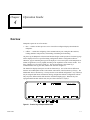
Datapanel Operator Interface Products Datapanel Model 240E User's Manual GFK-1656A March 2001 GFL-002 Warnings, Cautions, and Notes as Used in this Publication Warning Warning notices are used in this publication to emphasize that hazardous voltages, currents, temperatures, or other conditions that could cause personal injury exist in this equipment or may be associated with its use. In situations where inattention could cause either personal injury or damage to equipment, a Warning notice is used. Caution Caution notices are used where equipment might be damaged if care is not taken. Note: Notes merely call attention to information that is especially significant to understanding and operating the equipment. This document is based on information available at the time of its publication. While efforts have been made to be accurate, the information contained herein does not purport to cover all details or variations in hardware or software, nor to provide for every possible contingency in connection with installation, operation, or maintenance. Features may be described herein which are not present in all hardware and software systems. GE Fanuc Automation assumes no obligation of notice to holders of this document with respect to changes subsequently made. GE Fanuc Automation makes no representation or warranty, expressed, implied, or statutory with respect to, and assumes no responsibility for the accuracy, completeness, sufficiency, or usefulness of the information contained herein. No warranties of merchantability or fitness for purpose shall apply. ©Copyright 1999—2001 GE Fanuc Automation North America, Inc. All Rights Reserved. Preface Content of This Manual This manual describes features, installation, and operation of the Datapanel Model 240E product. Model Datapanel 240E Chapter 1. Quick Start: provides a simplified introduction and operation guide. Chapter 2. Introduction to the Datapanel 240E: provides an overview of capabilities, and system components, a brief functional description of the Datapanel 240E model, and features and capabilities. Chapter 3. Installing the Hardware: describes Datapanel installation. Chapter 4 Operation Guide: provides operational guidelines for Run Mode scenarios. Chapter 5. Special Operations: Mode Menu: outlines the use of the Mode menu to change display attributes and to operate the Datapanel in Off-line mode. Chapter 6. Specifications: provides tables listing the various hardware, technical, electrical, and other Datapanel system specifications. Appendix A. Error Codes: lists the standard comms block and system error codes. Appendix B. Glossary: provides a glossary of terms applicable to Datapanel operation. Related Publications GFK-1656A GFK-1658 Data Designer Software User’s Guide GFK-1475 WinCfg Software User’s Guide iii Contents Chapter 1 Quick Start ...................................................................................................... 1-1 Installing the Datapanel .......................................................................................... 1-1 Starting Up............................................................................................................. 1-1 Viewing Other Pages .............................................................................................. 1-1 Viewing Overview Groups ..................................................................................... 1-1 Printing a Page ....................................................................................................... 1-2 Displaying Alarms.................................................................................................. 1-2 Acknowledging Alarms .......................................................................................... 1-2 Adjusting Display Attributes .................................................................................. 1-2 Setting the Time and Date Display.......................................................................... 1-2 Non-Touch Models ........................................................................................ 1-2 Touch Models ................................................................................................ 1-2 Modifying the Process ............................................................................................ 1-3 Using Special Drive Out Capabilities...................................................................... 1-3 Password Protection ............................................................................................... 1-3 Chapter 2 Introduction to the 240E Datapanel ............................................................... 2-1 Overview of Datapanel Products................................................................................... 2-1 Configuration Software .......................................................................................... 2-2 Industrial Housing .................................................................................................. 2-2 System Components ............................................................................................... 2-3 Minimum Customer Supplied Hardware................................................................. 2-3 Datapanel Model 240E Specifics .................................................................................. 2-4 Datapanel Model 240E ........................................................................................... 2-4 Chapter 3 Installing the Hardware .................................................................................. 3-1 Physical Characteristics ................................................................................................ 3-1 Mounting Datapanels.................................................................................................... 3-2 Cables .......................................................................................................................... 3-2 Chapter 4 Operation Guide.............................................................................................. 4-1 Overview...................................................................................................................... 4-1 Typical Operation Scenarios ......................................................................................... 4-3 Routine Processing ................................................................................................. 4-3 Viewing Other Pages ............................................................................................ 4-3 Viewing Overview Groups.................................................................................... 4-3 Printing a Page...................................................................................................... 4-3 Alarm Conditions ................................................................................................... 4-4 Displaying Alarms ................................................................................................ 4-4 Acknowledging Alarms......................................................................................... 4-4 Additional Alarm Information ............................................................................... 4-4 Modifying the Process .................................................................................................. 4-6 Password Protection ............................................................................................... 4-6 Selecting a Tag and Entering a Value...................................................................... 4-6 GFK-1656A v Contents Special Drive Out Capabilities................................................................................ 4-6 Enhanced Drive Out.............................................................................................. 4-6 Chapter 5 Special Operations: Mode Menu .................................................................... 5-1 Exit .............................................................................................................................. 5-1 About Menu ................................................................................................................. 5-1 Display Control Menu .................................................................................................. 5-2 PLC Fault Screens ........................................................................................................ 5-2 Configuring PLC Fault Screen Options................................................................... 5-3 Selecting the PLC................................................................................................... 5-3 PLC Faults Screen.................................................................................................. 5-3 I/O Fault Screen ..................................................................................................... 5-4 Set PLC State ......................................................................................................... 5-4 Off-Line Mode ............................................................................................................. 5-5 Serial Ports Configure ............................................................................................ 5-5 Set Time and Date Display ..................................................................................... 5-6 Host Transfer ......................................................................................................... 5-7 Enable/Disable Alarms ........................................................................................... 5-7 Chapter 6 Specifications................................................................................................... 6-1 Hardware Specifications ................................................................................................ 6-1 Display................................................................................................................... 6-1 Backlight................................................................................................................ 6-1 Keypad................................................................................................................... 6-2 Technical Specifications ................................................................................................ 6-2 Electrical Specifications ................................................................................................ 6-3 Power Requirements............................................................................................... 6-3 Ports and Pinouts .................................................................................................... 6-4 Data Retention ........................................................................................................ 6-5 Real-Time Clock..................................................................................................... 6-5 Physical Specifications ........................................................................................... 6-5 Environmental Conformity ............................................................................................ 6-6 Appendix A Error Codes .....................................................................................................A-1 Standard Comms Block Error Codes............................................................................ A-1 System Error Codes ..................................................................................................... A-1 Controller Errors.......................................................................................................... A-1 Appendix B vi Glossary ...........................................................................................................B-1 Datapanel Model 240E User's Manual–March 2001 GFK-1656A Contents Figure 3-1. Datapanel Mounting Clamps ................................................................................................. 3-2 Figure 4-1. Function Keys of Datapanel Model 240E............................................................................... 4-1 Figure 4-2. Sample Alarm Logs............................................................................................................... 4-5 Figure 5-1. Mode Menu........................................................................................................................... 5-1 Figure 5-2. About Menu .......................................................................................................................... 5-2 Figure 5-3. Display Control Menu ........................................................................................................... 5-2 Figure 5-4. PLC Faults Log ..................................................................................................................... 5-3 Figure 5-5. PLC I/O Faults Screen........................................................................................................... 5-4 Figure 5-6. PLC Run/Stop Mode Screen.................................................................................................. 5-4 Figure 5-8. Set Ports Menu ...................................................................................................................... 5-6 Figure 5-9. Set Clock Menu..................................................................................................................... 5-6 Figure 5-10. Host Transfer Display.......................................................................................................... 5-7 Figure 6-1. Model 240E Ports and Pinouts............................................................................................... 6-4 GFK-1656A Contents vii Contents Table 2-1. Summary of Datapanel 240E Features and Capabilities........................................................... 2-5 Table 3-1. Physical Dimensions and Panel Cutouts.................................................................................. 3-1 Table 4-1. Alarm Log Characteristics ...................................................................................................... 4-5 Table 6-1. Display Area and Characteristics ............................................................................................ 6-1 Table 6-2. Backlight Type ....................................................................................................................... 6-2 Table 6-3. Keypad Characteristics ........................................................................................................... 6-2 Table 6-4. Technical Specifications ......................................................................................................... 6-2 Table 6-5. Power Requirements............................................................................................................... 6-3 Table 6-6. Data Retention Characteristics ................................................................................................ 6-5 Table 6-7. Real-Time Clock Characteristics............................................................................................. 6-5 Table 6-8. Physical Specifications ........................................................................................................... 6-5 Table 6-9. Environmental Conformity ..................................................................................................... 6-6 Table 6-10. Test Specifications................................................................................................................ 6-6 viii Datapanel Model 240E User's Manual–March 2001 GFK-1656A Chapter Quick Start 1 This chapter provides a simplified introduction and operation guide. See subsequent chapters for more detailed information and explanation. Installing the Datapanel After positioning the Datapanel in the cutout, secure it using the spring clamps supplied with the Datapanel. Refer to Chapter 4 for cutout dimensions. Connect the PLC-Datapanel cable between the PLC and the Datapanel. Connect the Datapanel power. Starting Up On power-up, the Datapanel will enter Run Mode and begin normal operation. The Start Up page will be displayed if one was specified during configuration with the configuration software. Otherwise, page 0 containing the logo will be displayed. Two lines of display are reserved for system use. The top line displays a mini alarm log, a communications error log, the date, and the time. The bottom line displays descriptive text for the function keys. Viewing Other Pages For a process that is running routinely, you would likely display a page which provides a good summary of process conditions. Other pages provide alternate views of the operation of the process. You can choose another page using a programmed function key. Alternatively, you can scroll through the pages by pressing the ▲ or ▼ keys (if enabled). Viewing Overview Groups Press OVERVIEW to see a list of Overview Groups which were configured for your application. The list of groups is displayed in pages, with up to 20 groups being listed on each page. Use <<< and >>> to move through the pages of the Overview list. Scroll through the pages of the Overview list until the required page is accessed. Use the ▲ or ▼ keys to select the required Overview Group from the displayed page. Press TAGS to display the tags and values associated with this group. You can return to the first page of the list at any time by pressing OVERVIEW. GFK-1656A 1-1 1 Printing a Page If the page being displayed has PRINT assigned to one of the F-keys, pressing that F-key will output the text content of the page to the printer. Serial printing is not available if both ports are used for PLC communications. Displaying Alarms Press ALARM LOG to display the Alarm Log. When a tag exceeds its limits, it will remain in the Alarm Log until it has been acknowledged and returns to normal or until it has been overwritten by tags alarming at a later time in an overflowing alarm log. An unacknowledged alarm is shown by an asterisk to the left of the alarm. Acknowledging Alarms Press ALARM ACK to acknowledge an alarm. The first press of the key clears the global alarm bit. Typically, this bit is sent to the controller to silence the audible alarm. Subsequent presses of the key clear each alarm in turn, starting with the earliest of the alarms. Press the ▲ or ▼ keys to access other pages of the log. Adjusting Display Attributes Press MODE to display the Mode Menu. Press DISPLAY to display the Display Control Menu. Press INCREASE or DECREASE repeatedly to adjust the contrast to the desired level. Note: The cursor may not respond to the touchscreen correctly after system has finished booting for the first time. Press EXIT to return to the main Mode Menu. Press EXIT to return to the displayed page. Setting the Time and Date Display Non-Touch Models Press MODE to display the Mode Menu. Press OFF-L to go off-line and display the Off-Line Mode Menu. Press CLOCK to display the Set Clock menu. Touch Models Press SET to access the pop-up screen touch numeric keypad. The active field is displayed at the top of the screen keypad. Press the up-down arrow keys (▲ ▼) to move from field to field on the on the display. Using the screen keypad, type in the desired values for each field in turn, press screen or on the physical keypad. Two-digit entry is required, e.g., 02 for February. Press UPDATE to confirm the entries, update the clock, and return to the main Off-Line Menu. 1-2 Datapanel Model 240E User's Manual – March 2001 GFK-1656A 1 Or, press EXIT to abort the option and return to the main Off-Line Menu without changing the clock settings. Press EXIT to return to the main Mode Menu. Access the Run Mode by pressing EXIT. Modifying the Process An operator can modify the ongoing process by using the Drive Out function of the Datapanel. This enables fresh values to be transmitted to any configured Drive Out tag. If a softkey has been configured for Drive Out, press that key to access the Drive Out function. A list of tags available for Drive Out and their associated index numbers will appear on the . display. Enter the index number using the numeric keypad or the numeric touch region. Press (If an incorrect value is entered, the message bad input is displayed and the value must be rea second time after a value entered.) Additional Drive Out tags may then be entered. Pressing has been transmitted terminates the Drive Out option, and the normal page will be displayed. Using Special Drive Out Capabilities Five types of Enhanced Drive Out can be configured: Toggle, Ramp, Recipe, Jog and Direct Write. If a tag with this capability is selected, the designation of the softkeys is re-assigned so that the user-defined labels for the toggle, ramp, recipe, jog or direct write functions will be displayed. On touch models, a special touch region may be displayed. Toggle. Pressing the F-key or touch region defined for the toggle function will invert the value of the configured item. For example, this could be used to switch a valve from on to off. Recipe. Pressing the F-Key defined for the recipe function will run the recipe feature configured. This can load a group of recipe tags with pre-defined values, transmit a group of recipe tags down to the PLC device, or perform both of these tasks with just one press of a key. Ramp. Pressing the F-key or touch region defined for the ramp function will display the current value and allow this value to be modified by pressing the up-down arrow keys (▲ ▼). . The new value is confirmed by pressing Jog (aka Momentary). Pressing and holding the F-key defined for the function will continuously send a value (set or reset) to the configured item while the F-key is depressed. When the operator releases the F-key, the opposite value will be sent. Direct Write. Pressing the F-key or touch region defined for the direct write function will either: 1. Drive Out a preconfigured value. 2. Request operator input of a value to Drive Out. Password Protection Some function(s) may be protected at the time of configuration. If so, a prompt is displayed asking for the password. The correct password for the particular option must be entered in answer to the prompt. An incorrect password aborts the request. GFK-1656A Chapter 1 Quick Start 1-3 Chapter Introduction to the 240E Datapanel 2 The Datapanel 240E provides a low-cost Human-Machine Interfaces enabling the transfer of data from a Programmable Logic Controller (PLC) and other intelligent control devices to a comprehensive operator terminal. The Datapanel is a self-contained, solid state industrial display system incorporating its own display screens and keypads. Overview of Datapanel Products Datapanel operator interfaces (OIs) are ideal replacements for discrete operator input and annunciation devices. Because of its many configurable options, a Datapanel can meet applications ranging from simple pushbutton replacement to complex interfaces beyond the capabilities of most small OIs.With a uniform software and hardware architecture, Datapanels allow you to produce an OI consistent with application budget and performance requirements while maintaining upgradeability. An expanding library of over 80 controller protocols is included with each Datapanel, meaning that a change in control hardware only requires reconfiguring communications and does not mean re-implementing the OI. With a consistent architecture, Datapanel hardware is scaled to meet the cost and performance requirements of each particular model. That means application software can run on all models, providing extensive functionality on even the lowest price Datapanel. Application software makes Datapanels perform with efficiency. A wide range of applications software is built into every model. An Operator Interface application is not restricted to emulating push buttons. Application software in Datapanels supports development of far more useful OI systems. Operator Interface software is included in every Datapanel. The software supports configuration of simple or complex OIs. Standard features of all Datapanel models include: GFK-1656A • Controller Communications. Read and write data to the control equipment via a serial port. • Integrated Keypad. Includes programmable function keys. • Broad Protocol Support. Over 80 protocols supported. • Analog and Digital Tag Scaling. Converts raw data to and from engineering units and adds tag name information. • Display Real-Time Data. Provide information on the current state of the plant process. 2-1 2 • Optional Display Modes. Continuous updates, update continuously only when page is displayed, update once when page is first displayed. • Alarm Manager. Checks for analog and digital alarms, maintains a log of active alarms and supports operator acknowledgment of alarms. • Graphic Page Display. Display static and dynamic text on up to 100 user configured pages per Datapanel. Multiple font sizes allow for emphasis of important data. • Softkeys. Six keys per page, for up to 600 user-defined buttons per Datapanel. Buttons may change pages, write data, or perform other OI functions. • Overview Display. Predefined tabular display of Datapanel and controller data. • NEMA 4X/4/12 Rated. Ruggedized for harsh industrial environments. Configuration Software Configuration of a Datapanel is quick and easy. Datapanels feature a common software environment, which means that configuring for one model is just like configuring for another. That increases productivity and decreases the time required to bring a Datapanel on-line. A PCbased software tool operating under Windows® is used to create a database for the Datapanel. The database and communications protocol are loaded to the Datapanel via a serial port, and the OI can then be put on-line. The configuration software is sold separately. A single copy of the configuration software can be used to configure any of the Datapanel Range. The configuration software requires a PC-compatible computer running either Windows 95®, Windows 98® or Windows NT operating system. Industrial Housing Datapanels are designed for use in demanding industrial applications. With over 15 years’ experience in meeting the requirements of industrial users, Datapanels avoid the problems that can plague lesser-quality products. All hardware is designed to meet industrial application requirements. Datapanels are of compact, shallow design. All front external surfaces are sealed and protected to NEMA 4X/4/12 (IP65) standards against the penetration of water and foreign particles. Datapanels are ideally suited for use as ruggedized panel-mounted units in harsh industrial environments. 2-2 Windows 95®, Windows 98®, and Windows NT® are registered trademarks of Microsoft Corporation Datapanel Model 240E User's Manual – March 2001 GFK-1656A 2 System Components A Datapanel system includes: • One unit from the Datapanel Range, incorporating an LCD display screen and membrane keypad and/or touch screen • Six Datapanel mounting clips • One Operator’s Manual (this book) Although Datapanels are self-contained units, a PC is required to to configure the system and when databases are being downloaded to the controller. Minimum Customer Supplied Hardware A PC or equivalent running Windows, is required to configure Datapanels and transfer databases and protocol to the Datapanel: GFK-1656A • 486 DX2/66 • 8 MB RAM • VGA Color Display • 20 MB Hard Disk Space Chapter 2 Introduction to the 240E Datapanel 2-3 2 Datapanel Model 240E Specifics A brief description of Datapanel Model 240E is given below. A summary of Datapanel features and capabilities is given in Table 2-1. Chapter 3 provides information on installing the Datapanels, Chapter 4 provides operational information, and Chapter 6 provides detailed specifications. Datapanel Model 240E The Datapanel Model 240E has a bright display area with the functionality increased by use of the touch-screen technology, more memory, black in color, adds PC/104 capability. If a flexible input system is a requirement for your OI application, the Datapanel Model 240E is the answer. A 48-point touch input system, six user function keys, and control keys enhance the versatility of the Model 240E. A bright 240 x 128 pixel LCD display offers excellent visibility. The panel cutout dimensions of the Model 240E are identical to the Model 240T, 320T and other Datapanel models. This allows a range of OI options to be offered without requiring modification to panel specifications. In addition to the basic Datapanel 240T runtime software, the Model 240E adds more memory, PC/104 capability, and the unit is provided in black. 2-4 Datapanel Model 240E User's Manual – March 2001 GFK-1656A 2 Table 2-1. Summary of Datapanel 240E Features and Capabilities Features GFK-1656A 240E Processor NEC V20-10MHz LCD Display Size (pixels) Mm (in.) 240x128 119.4 x 63.5 mm (4.7 x 2.5 in.) Mounting Dimensions (in.) 8.19 W x 7.40 H x 2.67 Deep; Panel Cutout 7.75 W x 6.97 H Display capability with minimum text size 40 char 14 lines Minimum Text Size (pixels) 6w x 8h Database Size 128k Backlight CCFT Memory, Flash 512KB Flash Memory, SRAM or DRAM 256KB SRAM Serial Ports One RS232, one RS232/RS485 Additional Ports No Standard Software Features Tag Scaling, Static and Dynamic data display, Alarm Manager, Read/Write to controller, Overview Display, Configurable Function Keys, Downloadable Database and Protocol, Variable text sizes, Dynamic, scalable bitmaps, Downloadable fonts, Meter and trend recorders. Bar Graphs Yes Bitmap Graphics Yes Real-Time Trends Yes Host Comms No PC/104 Expansion Yes Function Keys per Page Six Data Entry Keypad 10 keys Touch Screen Yes, 8 x 6 matrix Controller Protocols: Over 80 supplied, including GE Fanuc, Modicon, Allen Bradley, Square D, Mitsubishi, Omron, Siemens, etc. Call for details Analog Tags 500 Digital Tags (2 bits per tag) 500 Display Pages 100 NEMA, UL, CUL, CE 4X/4/12, UL, CUL, Class I Div II, CE Chapter 2 Introduction to the 240E Datapanel 2-5 Chapter Installing the Hardware 3 Physical Characteristics Datapanels are housed in two molded enclosures forming the front and the rear sections of the unit. The front section of model 240E forms a bezel with a large central aperture giving access to the LCD display and to the membrane keypad. The system hardware is mounted to the rear section with a gasket located between the front and rear sections to ensure conformity with IP65 (NEMA 4X/4/12) rating. The rear section of the housing is a simple cover designed to fully enclose the system hardware. The two sections are secured to one another by snapping them together; the four plastic clips (one located near each corner) should fully latch to one another. The physical dimensions and the required panel cutouts are shown in Table 3-1. Table 3-1. Physical Dimensions and Panel Cutouts Features GFK-1656A Model 240E Dimensions (Inches) 8.19 Wide x 7.40 High x 2.67 Deep Panel Cutout (Inches) 7.75 Wide x 6.97 High 3-1 3 Mounting Datapanels The Datapanel comes with a gasket glued in place on the bezel to ensure compliance with protection ratings. The Datapanel is secured using miniature screw clamps. The mounting points for the clamps are located on the front section of the Datapanels. Access to the rear of the unit is necessary so that clamps can be fitted. After the Datapanel has been positioned in the cutout, the unit is then secured using the spring clamps as shown in Figure 4-1. Working from the rear of the panel, locate the clips in the slots shown in the diagram and marked A. The clamps should be tightened evenly so as to cause the nuts to rise up the screw threads and thus close the springs. It is important that the screws are not over-tightened, as the springs may then be deformed, resulting in an improper mounting of the Datapanel. A total of six clamps are used to secure Model 240E. Clamp Slot Locations Clamp Mounting Detail Figure 3-1. Datapanel Mounting Clamps Cables Two cables are required when using the Datapanels: 3-2 • The download cable is used when transferring databases or protocols from the configuration software to the Datapanel. The cable enables connection to a standard PC. For nonstandard PCs, consult the PC manual to check the pin configuration at the PC end of the cable. This cable is supplied with the configuration software. • The cable used to connect Datapanels to the controller. As a general guide, the only pin connections required at the Datapanel end are Tx, Rx, Signal, Ground; with RTS connected to CTS. Refer to your controller documentation for details of connections at the controller end. This cable is not supplied with the Datapanel. Datapanel Model 240E User's Manual – March 2001 GFK-1656A Chapter Operation Guide 4 Overview Datapanels operate in one of two modes: • Run — enables real time processes to be viewed from configured displays downloaded to Datapanel. • Offline — enables the configuring of the communications port, setting the date and time, loading databases and protocols, and enabling or disabling alarm checking. On power-up, the Datapanel will enter Run Mode and begin normal operation. The Start Up page will be displayed if one was specified during configuration with the configuration software. Otherwise, page 0 containing the logo will be displayed. The screen layouts of all Datapanels are similar in appearance, but vary slightly according to the capabilities of the various models. Two lines of display are reserved for system use. The top line displays a mini alarm log, a communications error log, the date, and the time as shown in Figure 5-1. The bottom line displays descriptive text for the function keys. One of the obvious differences between various Datapanel models is the number and location of the function keys (F-keys). The Model 240E has six function keys. The keys shown are the default configuration. Any of the keys may be assigned other labels and functions during configuration with the configuration software. They may have different labels and functions on different display pages. When the keys are reprogrammed from their default value, they are often referred to as softkeys. E Figure 4-1. Function Keys of Datapanel Model 240E GFK-1656A 4-1 4 The default Run Mode function keys are: 4-2 • PAGE — displays configured pages. Often, the first page is configured as an index or menu of all other pages. • OVERVIEW — displays configured Overview Groups. • ALARM LOG — displays the Alarm Log. • DRIVE OUT — allows the operator to write to the controller. • MODE — allows the operator to switch between the Run Mode and Off-line. • ALARM ACK — allows the operator to acknowledge alarms. Datapanel Model 240E User's Manual – March 2001 GFK-1656A 4 Typical Operation Scenarios Routine Processing For a process that is running routinely, you would likely display a page which provides a good summary of process conditions. The page might include a trend chart showing performance over some time period, a bar chart showing the availability of a critical process supply, and other elements showing constantly updating values of parameters indicating process efficiency (e.g., cans filled per hour, gallons of fruit juice per minute, kW of electricity consumed). Viewing Other Pages Other pages provide alternate views of the operation of the process. For instance, this would be useful if you noticed a change in some parameter and you wanted more detail on that aspect of the process. You can choose another page by using a preconfigured function key). Alternatively, you can scroll through the pages by pressing the ▲ or ▼ keys (if activated). The ▼ key displays the next page; the ▲ key displays the previous page. The logo page or the Start Up page will appear when you press PAGE. If so configured by the configuration software, the Start Up page may show a list or menu of other pages. If so configured, you can use a redefined F-key or a touch region to access other pages. Viewing Overview Groups Press OVERVIEW to see a list of Overview Groups which were configured for your application. Each group contains a maximum of 10 configured tags, which have been grouped together during configuration because they are relevant to each other, e.g., temperatures or pressures. There may be up to 100 groups. The list of groups is displayed in pages, with 20 groups listed on each page. When the OVERVIEW key is pressed, the designation and function of some of the softkeys change. For instance, one of the F-key labels displays a left-chevron design (<<<) and another displays a right-chevron design (>>>). Use <<< to move backwards through the pages of the Overview list. Use >>> to move forwards through the pages of the Overview list. Scroll through the pages of the Overview list until the required page is accessed. The range of Overview Groups on a particular page of the list is shown at the top of the display. Use the ▲ or ▼ keys to select the required Overview Group from the displayed page. Press TAGS to display the tags and values associated with this group. You can return to the first page of this list at any time by pressing OVERVIEW. Printing a Page If the page being displayed has PRINT assigned to one of the F-keys, pressing that F-key will output the text content of the page to the printer. For instance, you may want to do this at the end of a shift in order to have a permanent record of conditions at that time. Graphics on the page will not be printed. Printing is not available if both ports are being used for PLC communications (multicomms). GFK-1656A Chapter 4 Operation Guide 4-3 4 Alarm Conditions If one of the configured tags exceeds its limits, an alarm message will appear in the mini alarm log window and be added to the Alarm Log. Press the ALARM ACK F-key or touch region to acknowledge the alarm(s). Displaying Alarms Press ALARM LOG to display the Alarm Log. Sample Alarm Logs are shown in Figure 5-2. The capacity and display characteristics of the logs depend on the Datapanel type and are described in the table below. If the capacity of the log is exceeded, the earlier alarms will be lost. When a tag exceeds its limits, it will remain in the Alarm Log until it has been acknowledged and returns to normal or until it has been overwritten by tags alarming at a later time in an overflowing alarm log. Unacknowledged alarms are indicated with an asterisk. Acknowledging Alarms Press ALARM ACK to acknowledge an alarm. The first press of the key clears the global alarm bit. Typically, this bit is sent to the controller to silence the audible alarm. Subsequent presses of the key clear each alarm in turn, starting with the earliest of the alarms. Press the ▲ or ▼ keys to access other pages of the log. Additional Alarm Information If the Datapanel has been configured to do so, selected alarms will be printed automatically as they occur. The mini Alarm Log shows the earliest unacknowledged alarm. The mini Alarm Log is updated as each alarm is acknowledged. When all alarms have been acknowledged, the mini Alarm Log is removed until another alarm condition occurs. The ALARM LOG function key is displayed only if alarms are enabled. If the alarms were configured disabled or have been disabled in the Off-line option, the ALARM LOG and ALARM ACK function keys will be displayed blank. 4-4 Datapanel Model 240E User's Manual – March 2001 GFK-1656A 4 Table 4-1. Alarm Log Characteristics Model 240E Alarm Capacity 50 Alarms/Page 10 Mini Alarm Log 10 characters of tag name ACK method * in ACK symbol column means not acknowledged Analog Alarms st 1 Column ACK symbol 2nd Column 10 characters of tag name 3rd Column 4 characters of alarm type 4th Column 10 characters of value 5th Column 5 characters of units th 6 Column 8 characters of time 7th Column not used Digital Alarms st ACK symbol nd 10 characters of tag name 1 Column 2 Column rd 3 Column 4 characters of alarm type 4th Column 16 characters of status 5th Column not used 6th Column 8 characters of time 7th Column not used Figure 4-2. Sample Alarm Logs GFK-1656A Chapter 4 Operation Guide 4-5 4 Modifying the Process An operator can modify the ongoing process by using the Drive Out function of the Datapanel. This enables fresh values to be transmitted to any configured Drive Out tag. If a softkey has been configured for Drive Out, press that key to access the Drive Out function. Password Protection The Drive Out function is usually password protected at the time of configuration. If so, when Drive Out is attempted, a prompt is displayed asking for the password. As there are three Drive Out options, three Drive Out passwords may have been configured, referenced to which display you have on the screen when you request Drive Out: Page, Monitor, or Overview. The correct password for the particular option must be entered in answer to the prompt. An incorrect password aborts the request. The Drive Out procedure is largely the same for each of the three options. Selecting a Tag and Entering a Value A list of tags configured by the user is displayed on the screen. When a drive-out operation is initiated, the associated index numbers for those tags will appear on the display. Enter the index . (If an incorrect value is number using the numeric keypad or the numeric touch region. Press entered, the message bad input is displayed, and the value must be re-entered.) Additional Drive a second time, after a value has been transmitted, Out tags may then be entered. Pressing terminates the Drive Out option, and the normal page will be displayed. Special Drive Out Capabilities Enhanced Drive Out Five types of Enhanced Drive Out can be configured: Toggle, Ramp, Jog, Recipe, and Direct Write. If a tag with this capability is selected, the designation of the softkeys is re-assigned so that the user-defined labels for the toggle, ramp, jog, recipe, or direct write functions will be displayed. On touch models, a special touch region may be displayed. Toggle Pressing the Function-key or touch region defined for the toggle function will invert the value of the configured item. For example, this could be used to switch a valve from on to off. Ramp Pressing the Function-key or touch region defined for the ramp function will display the current value and allow this value to be modified by pressing the up-down arrow keys (▲ ▼). The . new value is confirmed by pressing Recipe. Pressing the F-Key defined for the recipe function will run the recipe feature configured. This can load a group of recipe tags with pre-defined values, transmit a group of recipe tags down to the PLC device, or perform both of these tasks with just one press of a key. 4-6 Datapanel Model 240E User's Manual – March 2001 GFK-1656A 4 Jog Pressing and holding the Function-key defined for the function will continuously send a value (set or reset) to the configured item while the F-key is depressed. When the operator releases the F-key, the opposite value will be sent. Direct Write Pressing the Function-key or touch region defined for the direct write function will either: GFK-1656A 1. Drive Out a preconfigured value. 2. Request operator input of a value to Drive Out. Chapter 4 Operation Guide 4-7 Chapter Special Operations: Mode Menu 5 The Mode menu is normally not used during routine operation of the Datapanel. It allows the operator to display information about the Datapanel, change the attributes of the display, or operate the Datapanel in the off-line mode. Press MODE to display the Mode Menu. E Figure 5-1. Mode Menu Exit Press EXIT to return to the startup page. About Menu Press ABOUT to display information about the Datapanel as shown in Figure 5-2. This information cannot be edited. Press MORE to display the configuration of the port settings. Press EXIT to return to the main Mode menu. GFK-1656A 5-1 5 240E Figure 5-2. About Menu Display Control Menu Press DISP to view the Display Control Menu. This menu allows the operator to change the display contrast setting or reverse the display. Unless the backlight is configured OFF with WinCfg, the default is ON. Display Control Options - Models 240E Figure 5-3. Display Control Menu Press INC repeatedly to increase the contrast to the desired level. Press DEC repeatedly to decrease the contrast to the desired level. Press EXIT to return to the main Mode menu. PLC Fault Screens The PLC fault screen is available from the Mode menu if the SNP/SNP-X (protocol 68) is configured. F5 is labeled FAULT. These screens allow the user to view the current run-mode of a PLC device and its PLC and I/O Fault tables. If write privileges are enabled, these tables may be cleared from the Datapanel and the run-mode changed. 5-2 Datapanel Model 240E User's Manual – March 2001 GFK-1656A 5 Configuring PLC Fault Screen Options Additional configuration is required if the Datapanel is used in a multi-drop application or the Datapanel is to have the ability to modify the fault table or the run-mode of the PLC. If a multidrop network is connected to the Datapanel, the SNP IDs of the PLCs must be entered using the PC configuration tool . Similarly, if the Datapanel is to have write privileges, this must be set with the PC configuration tool. Neither of these options is the default. Selecting the PLC If a multi-drop network is used, or SNP/SNP-X is chosen for both Port 1 and Port 2, the user will be prompted for which PLC they wish to communicate with after pressing FAULT on the MODE screen. The arrow keys may be used to highlight the correct SNP ID and the F-key labeled PORT toggles the communication port selection. The ENTER F-key continues to the PLC Faults screen. PLC Faults Screen This screen displays the PLC Faults log of the PLC. Figure 5-4. PLC Faults Log Information is presented as follows: Fault lists the displayed fault number out of the total number of faults registered in the system. Location gives the rack and slot that reported this fault. Desc provides a short text description of the problem. Actual shows the current time in the PLC. Fault provides the time stamp of the reported fault. Since the PLC clock may not be synchronized with the Datapanel, these entries can be significantly different from the Datapanel time and/or the current time of day. If DIAG is pressed, the Fault Code and Fault Data lines appear. These provide more detailed fault codes that can be referenced n GE-Fanuc literature or with technical support. Other function keys at the bottom of the screen include: RUNST, which changes to the Set PLC State page; IOFLT, which changes to the I/O Faults page; and EXIT, which returns to the MODE screen. If write privileges are enabled, the fifth function key will be labeled CLEAR. Pressing it GFK-1656A Chapter 5 Special Operations: Mode Menu 5-3 5 will clear the PLC fault log in the PLC. If the PLC is password protected, the user will be prompted for a Level 2 SNP password. I/O Fault Screen The I/O Fault Screen displays the I/O Faults log in the PLC. Figure 5-5. PLC I/O Faults Screen The fields are similar to those in the PLC Faults screen. Circ No is the point on a multi-point card, such as digital input 4 of a 16-pt module. Reference address provides the PLC table mapping of the card. Set PLC State This screen allows the user to view and modify the PLC’s run-state. Figure 5-6. PLC Run/Stop Mode Screen Current Mode states the present mode of the PLC. New Mode will change to reflect the last button the user pressed from four mode options. R.ENB will change the new mode to Run Mode, I/O enabled. R.DIS (only available for certain PLC models) will change the new mode to Run Mode, I/O disabled. S.DIS will change the new mode to Stop Mode, I/O disabled. S.ENB will change the new mode to Stop Mode, I/O enabled. 5-4 Datapanel Model 240E User's Manual – March 2001 GFK-1656A 5 UPDAT is only available if write permissions have been set in the PC Configuration tool. Pressing update will attempt to change the current mode to the new mode selected. If the PLC is password protected, the user will be prompted for a Level 2 SNP password. Successful operation is marked by the current mode changing to the new setting. EXIT returns to the PLC or I/O Fault screen. Off-Line Mode The Off-line mode enables the operator to configure the communications port, set the date and time, load databases and protocols, and enable or disable alarm checking. When the Off-Line option is accessed, all controller communications and alarms are inactive and the mini alarm log is not displayed. The real time clock is not displayed but is running as a background task. This function is usually password protected at the time of configuration. If so, when Off-Line is attempted, a prompt is displayed asking for the password. The correct password must be entered in response to the prompt. An incorrect password aborts the attempt to go off-line. Press OFF-L to go off-line and display the Off-Line Mode menu shown in Figure 5-7. When finished, Press EXIT to return to the main Mode menu. The system will revert to the main Mode Menu but will remain Off-line until Run Mode is accessed by pressing EXIT. The clock and the mini alarm log will again display. O ff-L in e M od e – M od e l 2 40 E Figure 5-7. Off-Line Mode Menu Serial Ports Configure Press PORT to display the Set Ports Menu shown in Figure 5-8. This option also enables the display and modification of the configured settings for Port COM1 and Port COM2, if present. When finished, press EXIT to return to the Off-Line Mode menu. GFK-1656A Chapter 5 Special Operations: Mode Menu 5-5 5 E Figure 5-8. Set Ports Menu Press PORT to toggle between COM1 and COM2 to select the desired port. Press BAUD RATE repeatedly to scroll through the available baud rates to select the desired rate. Press CHAR BITS repeatedly to toggle between 7 and 8 to select the desired number of character bits. Press STOP BITS repeatedly to toggle between 1 and 2 to select the desired number of stop bits. Press PARITY repeatedly to scroll through the available parity choices to select the desired parity. Press EXIT to return to the Off-Line Mode menu. Set Time and Date Display Press CLOCK to display the Set Clock menu shown in Figure 5-9. Figure 5-9. Set Clock Menu Press SET to access the pop-up screen touch numeric keypad. The active field is displayed at the top of the screen keypad. Press the up-down arrow keys (▲ ▼) to move from field to field on the on the display. Using the screen keypad, type in the desired values for each field in turn, press screen or on the physical keypad. The active field will automatically advance to the next field. The screen keypad can be relocated by simply touching the screen wherever you want the pad located. Press UPDATE to confirm the entries, update the clock, and return to the main Off-Line Menu. 5-6 Datapanel Model 240E User's Manual – March 2001 GFK-1656A 5 Press EXIT to abort the option and return to the main Off-Line Menu without changing the clock settings. Host Transfer Press TXFR to access the Host Transfer display and enable data transfer between the Datapanel and the configuration software PC. To exit the transfer, press ABORT. Figure 5-10. Host Transfer Display The actual transfer of the data is under the control of the PC. The following messages will be displayed in the message area of the display: When downloading a Protocol: Loading Communications Protocol ... and on the same line when complete, Protocol installed. When downloading a Database: Loading Database ... and on the same line when complete, Database installed. When uploading a Database: Uploading Database ... and on the same line when complete, Database transferred. When a communications error occurs: Transfer Failed Enable/Disable Alarms Press ALARM to access the alarm option. The label of one of the F-keys will change to ENABLE, another will change to DISABLE. Press ENABLE to enable alarms. Press DISABLE to disable alarms. Press EXIT to return to the Off-Line Menu. This option is useful to prevent excessive alarm logging during periods of operation with known process discrepancies or during process testing. GFK-1656A Chapter 5 Special Operations: Mode Menu 5-7 Chapter Specifications 6 Hardware Specifications Display Text can be displayed in a variety of sizes by changing the height and width of the text. The default size is displayed with a height and width of 1 x 1 (see table below for pixel relationships). This can be increased so that text of 4 x 4 size can be configured. Two lines of the display are reserved for system use. The top line displays the date and time and any communications errors. The bottom line displays descriptive text for the function keys. The display area and display characteristics of the models in the Datapanel Range are specified in Table 6-1. Table 6-1. Display Area and Characteristics Features 240E LCD Display Size (pixels) Mm (in.) 240 x 128 119.4 x 63.5 (4.7 x 2.5) Display capability with minimum text size 40 char 14 lines Minimum Text Size (pixels) 6w x 8h Touch Models Overlaid on the display area is a resistive touch membrane divided into rows and columns providing touch regions that can be configured by the user. On the Model 240E 48 touch regions are provided. Backlight The backlight type is given in Table 6-2. Operation of the backlight is defined during configuration by the configuration software. In addition, the operator can control the backlight using the membrane key pad. GFK-1656A 6-1 6 Table 6-2. Backlight Type Features 240E Backlight CCFT Keypad All Datapanels incorporate built-in membrane keypads with audible feedback as described in Table 6-3. Table 6-3. Keypad Characteristics Features 240E Function Keys per Page Six Data Entry Keypad 15 keys Touch Screen Yes 8 x 6 touch regions Touch Models The use of a resistive overlay on the touch models of the Datapanel Range has enabled the development of a much simpler membrane keypad with the resistive touch areas being configured for most of the operator keying functions. Technical Specifications The technical specifications are given in Table 6-4. Table 6-4. Technical Specifications Features 6-2 240E Processor NEC V20-10MHz Memory, Flash 512KB Flash Memory, SRAM or DRAM 256K SRAM Database Size 128K Serial Ports One RS232, one RS232/RS485 Additional Ports No Datapanel Model 240E User's Manual – March 2001 GFK-1656A 6 Electrical Specifications Power Requirements The power requirements are given in Table 6-5. Power Requirements The steady state current consumption of the Datapanel is dependent on the supply voltage. At power-up, the Datapanel briefly requires a larger current to operate correctly. To ensure correct power-up, the external power supply must be able to provide a current of at least 1 A, irrespective of the supply voltage. The power for the Datapanel Model 240E can be supplied either through the 4-pin power connector or through pins 14 - 17 on the 25-pin connector. However, pins 14 - 17 are intended only as a secondary power input option for end-users wishing to supply power from the controller. It is recommended that power be supplied via the dedicated input connector. Table 6-5. Power Requirements Features Power Input GFK-1656A Chapter 6 Specifications 240E 12 – 35VDC, 24VAC (750mA@12VDC) 6-3 6 Ports and Pinouts Ports and pinouts are given in the following figures. Model 240E * 9: RS485 Mode Select 10: 485 TX11: 485 TX+ 9-pin Printer Port Model 240E 12: 485 RX-/TX13: 485 RX+/TX+ * OV = 2 wire; Floating = 4 wire 25-pin Serial Port Model 240E Figure 6-1. Model 240E Ports and Pinouts 6-4 Datapanel Model 240E User's Manual – March 2001 GFK-1656A 6 Data Retention Data retention characteristics are given in Table 6-6. Table 6-6. Data Retention Characteristics 240E Backup is provided for SRAM by the use of a lithium energy cell integrated within the Real-Time Clock circuit (not user replaceable). Battery Life Typical: 10 years Worst: 5 years The battery life figures constitute total ‘offtime’. For a Datapanel powered on half-time, the worst battery life figure would be at least 10 years. Real-Time Clock Real-time clock characteristics are given in Table 6-7. Table 6-7. Real-Time Clock Characteristics 240E Real-Time clock standard Physical Specifications Physical specifications are given in Table 6-8. Table 6-8. Physical Specifications 240E Dimensions (Inches) GFK-1656A Chapter 6 Specifications 8.19 Wide x 7.40 High x 2.67 Deep Weight (lb.) 2.5 Panel Cutout (Inches) 7.75 W x 6.97 H 6-5 6 Environmental Conformity Environmental conformity is given in Table 6-9. Table 6-9. Environmental Conformity Features NEMA, UL, CUL, CE 240E 4X/4/12, UL, CUL, Class I Div II, CE All models in the Datapanel Range are designed to satisfy the requirements and conditions of the following specifications. All units in the Datapanel Range remained operational when tested for temperature, humidity and vibration to the specifications shown in Table 6-10. Table 6-10. Test Specifications All Models Temperature 6-6 Operating Temp. 0 to +50 °C, Storage Temp. -20 to +60°C Humidity 5 to 85 % non-condensing Vibration 0.075 mm peak for 10 to 81 Hz, 2 G from 81 to 1000 Hz Datapanel Model 240E User's Manual – March 2001 GFK-1656A Appendix Error Codes A Standard Comms Block Error Codes 101 Timeout 102 Checksum Received Error 103 Bad Character Received Format Error 104 Bad Message Framing Error 105 Bad Message Format Received 106 NAK Response Received 107 Comms Block Format Error 108 Invalid Command System Error Codes 29 More than eight page-activated comms blocks activated by the page. 120 Tag Conversion error — unreasonable limits configured in an Analog Tag Record. 121 No Comms File. 122 No Comms Blocks. 123 Invalid Comms Block Time base. 124 Invalid Comms Block Type. Controller Errors If any errors are displayed which are not listed in the above tables, reference should be made to the configuration software Help system or to the controller documentation. GFK-1656A A-1 Appendix Glossary B ACK Acknowledgment Alarm Alarm Limits Alphanumeric Alphanumeric Display Analog Analog Tag Analog Variable ANSI Application Program Area Coloring ASCII Attributes Background Color Backup Bar Graph Baud, Baud Rate Bit Bit Table Bitmap Blinking Browse Byte GFK-1656A See Acknowledgment. The action taken by the user to indicate the acceptance of the information presented by the system. An abnormal situation detected by the system. The violation of predefined limits by an input variable from the plant. Limits set at the time the Datapanel is configured. Alphabetic and numeric characters only. A display of alphabetic and numeric characters only. The characteristic of being able to take on any of a continuously variable range of values. An identifying name for an analog variable. See also Tag. A term used to describe a 16-bit integer, 32-bit integer, or floating-point number which may take many values. A character set optimized for the support of the French, German and Scandinavian characters. A user-defined program written to perform specific actions in addition to the system software functions. The coloring of a defined display area with a defined color. American Standard for Computer Information Interchange. Defines what numeric codes are used to represent numbers, punctuation and letters of the alphabet. The characteristics assigned to a graphic element such as: Blink, Position, Color. That part of the display that appears not to change as contrasted with a bar graph which changes with the value of the displayed parameter. To copy and store data as a precaution against loss or damage. Also, the copy so created. A filled rectangular area whose height or horizontal length changes in proportion to a variable. User-configurable rates at which communication takes place between the system and the controller. A binary value of 0 or 1. An area of memory dedicated to storing a binary value. An area of memory dedicated to storing multiple bits. A file that stores a graphic image in terms of bits. These bits are mapped to the screen to create the image. The effect created on a portion of a graphic which will allow it to change between two defined states at a specific rate. Scanning data in order to locate a required item. A group of 8 consecutive bits. B-1 B Commands Comms Block Communications Block (Comms Block) Communications Protocol Configure Contiguous Controller Data Data Designer software Database Datapanel Datapanel Address Digital Digital Tag Download Drive Out Drop-Down Dynamic Firmware F-Key Flash memory Function Key HMI (HumanMachine Interface) Host I/O Import Input/Output Keyboard Keypad LED Macro Master B-2 Information sent from the Datapanel to the controller to control or modify the plant process. See Communications Block. A group of user configured information describing a particular communications operation between the Datapanel and the controller. The “language” to be used when the system communicates with a controller. It contains the rules used to establish contact, receive/transmit data, detect transmission errors, etc. To set up the display system in accordance with the needs of a particular user. This includes user-specific displays, alarm criteria, etc. A group of items stored in adjacent locations. An industrial device that handles the Input/Output of plant voltages and signals, e.g., a Programmable Logic Controller. Information relating to the operation of the plant process. A Windows-based tool for configuring Datapanels. A structured set of data. In the Datapanel, databases are configured to customize the product to satisfy the needs of the user. A self-contained, solid-state industrial display system incorporating its own display screen and keypad. The Datapanel Register or Bit Table address to or from which data is to be transferred. The characteristic of being able to take on only one of two possible states or conditions. An identifying name for a digital variable. See also Tag. Transmitting data from the configuration software tool to the Datapanel. The capability of the Datapanel which allows it to send information to the controller. A menu or list which appears in Windows upon selection of a menu item. Any data element (tag value, graphic item, etc.) that can have changing values. Software (database, applications) stored in non-volatile memory, e.g., EPROM. See Function Key. See Firmware. A key on a keyboard or keypad whose function is determined by software and may vary depending on the state of the software. Current definitions of the Datapanel function keys are displayed on the screen. Device enabling the two way transfer of data between a human and machine. Device on which the controlling software is resident. See Input/Output. The ability to transfer configuration information into the Datapanel configuration tool from another application like a spread sheet. A general expression for the input and output of binary data to or from a device. A collection of physical keys used by the user to communicate with the computer system. An operator keyboard with a reduced number of keys, e.g., numeric and/or function keys. Light Emitting Diode. Typically used as a status indication light. A collection of graphic elements used repeatedly thereafter in subsequent displays. This graphic application of the term differs from a macro instruction, a collection of instructions or program statements which can be activated collectively. The device controlling network communications. Datapanel Model 240E User's Manual –March 2001 GFK-1656A B Membrane Mimic Mini-Alarm Log NEMA Network Off-line On-line Operator Overview Group Page Parallel Parameter Parity Password PC Pixel Plant Process PLC Process Process Variable Programmable Logic Controller Protocol RAM Ramp Drive-out Raw Data Real-Time Data Register Remote Address Run Time Scaled Data Serial Slave System Register Tag GFK-1656A Appendix B Glossary A continuous film intended to protect a device from the ingress of dust or liquid. A display which factually represents the plant. It provides the status of each displayed plant item. Mimics may be shown on monitors or wall displays. One of the Alarm area displays available when using the Datapanel. This display is found on all the Run Mode displays in the upper part of the screen. National Electrical Manufacturers Association. A group which sets American standards for enclosures which protect electronic equipment from the adverse affects of liquids, ingress of dust and physical shocks. Also, the standard created. An interconnected group of communicating devices. A condition where run time operations are suspended, so that system settings can be changed. The system is communicating to external devices with dynamic data being updated. The person who uses the system for its practical purpose such as to interface with the plant process. Not necessarily the one who configured the system. See also User. A set of tags configured to be displayed together. One of 100 user configurable displays on the Datapanel. A data transfer mechanism using multiple transfer paths. A value set when the system is configured. The means of checking the validity of a data character. A code used to show the authority of the user to gain access to various sensitive features of the system. For example, changes to the display design would normally be password-protected to guard against changes by unauthorized users. IBM Personal Computer or any computer generically similar. The smallest picture element of a display surface that can be independently assigned a color or intensity. A series of actions or treatments designed to produce a desired end under the control or monitoring of a PLC or other intelligent controller. Programmable Logic Controller. See Plant Process. A variable parameter of the production process. An industrial device that handles the Input/Output of plant voltages and signals. The format, structure and procedure required to communicate with a controller. Random Access Memory. Pre-configured analog drive-out (Tag/Register) with a specific increment/decrement value. Data read from the controller before being scaled into engineering values. Current data. An internal memory location used for storing 16-bit representation of analog data in the Datapanel or controller. The register or bit table address in the controller to or from which data is to be transferred. The operating state of the system. See also On-line. Raw data whose value has been modified to conform to prescribed engineering units. A data transfer mechanism using a single transfer path. The device which responds to a master over a network. Same as any other register (see Register) but reserved for use by the system and cannot be modified by the user.. An analog or digital variable held in the Datapanel, usually representing an analog or digital variable in the controller. Includes additional information such as a name, size of the controller variable, scaling factors, alarm limits, etc. B-3 B Tag Record Tag Table Tag Value Toggle Toolbar Touch Region Trend Upload User WinCfg software B-4 An area of the database containing the information for a particular tag. A group of Tag Values in the Datapanel. The current value of the tag. This may be a scaled engineering value associated with the Tag Record. The action of inverting the value of a two-state item, such as a bit or a two-state digital tag. A group of icons which provide easy access to other windows, menus or operations. An area of the screen dimensionally defined to produce a program response when touched or pressed. The graphical display of a variable in the form of a trace drawn with reference to X and Y coordinates. Database transfer from Datapanel to WinCfg. The person using WinCfg to configure a Datapanel. See also Operator. A Windows-based tool for configuring Datapanels. Datapanel Model 240E User's Manual –March 2001 GFK-1656A Index A Acknowledging alarms, 4-4 Additional alarm information, 4-4 Alarm conditions, 4-4 Alarm log characteristics, 4-5 B Backlight, 6-1 C Cables, 3-2 Configuration software, 2-2 Customer supplied hardware, 2-3 Cutouts, panel, 3-1 D Data retention, 6-5 Datapanels features and capabilities, 2-5 Model 240E, 2-4 mounting, 3-2 operating modes, 4-1 overview, 2-1 physical characteristics, 3-1 Dimensions panel cutouts, 3-1 Direct Write, 4-7 Displaying alarms, 4-4 E Electrical Specifications, 6-3 Enhanced drive out, 4-6 Entering a value, 4-6 Error codes, A-1 F I Industrial housing, 2-2 Installation, 3-1 J Jog, 4-7 M Mode menu, 5-1 Modifying the process, 4-6 Mounting Datapanels, 3-2 O Offline mode, 4-1 Operating modes overview, 4-1 P Panel cutouts, 3-1 Password protection, 4-6 PC requirements, 2-3 Physical characteristics, 3-1 Physical specifications, 6-5 Pinouts, 6-4 Ports, 6-4 Power requirements, 6-3 Printing a page, 4-3 Q Quick Start, 1-1 R Ramp, 4-6 Real-time clock, 6-5 Run mode, 4-1 Function keys run mode, 4-2 G Glossary, B-1, B-4 H Hardware specifications, 6-1 GFK-1656A S Selecting a tag, 4-6 Special drive out capabilities, 4-6 Specifications data retention, 6-5 display, 6-1 electrical, 6-3 hardware, 6-1 keypad, 6-2 physical, 6-5 Index-1 Index ports and pinouts, 6-4 Real-time clock, 6-5 technical, 6-2 System components, 2-3 T Technical specifications, 6-2 Toggle, 4-6 Typical operation scenarios, 4-3 V Viewing other pages, 4-3 Viewing overview groups, 4-3 Index-2 Datapanel Model 240E User's Manual–March 2001 GFK-1656A