1
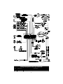
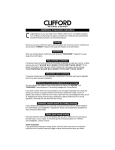
AutoFax & Technical Support Helpline:
1-800-444-4667
For the latest vehicle wiring information and for
wiring diagrams and servicing information on
older Clifford products:
24-hour AutoFax: 1-800-444-4667
24-hour dealer website: www.clifforddealer.com
Clifford Electronics, Inc. n 20750 Lassen Street n Chatsworth, CA 91311
1-800-824-3208 or 1-818-709-7551 n fax 1-818-407-1743
4
Table of Contents
Important Information . . . . . . . . . . . . . . . . . . . . . . . . . . . . . . . . 2
Standard Features of the Tazor 4 . . . . . . . . . . . . . . . . . . . . . . . . . . 3
System Components . . . . . . . . . . . . . . . . . . . . . . . . . . . . . . . . . 3
Wiring Diagram . . . . . . . . . . . . . . . . . . . . . . . . . . . . . . . . . . . 4
Wiring Description - 2-Pin Connector . . . . . . . . . . . . . . . . . . . . . . . . 4
Wiring Description - 24-Pin Connector . . . . . . . . . . . . . . . . . . . . . . . 5
Passenger Compartment Connections . . . . . . . . . . . . . . . . . . . . . . . . 5
Control Unit and Antenna . . . . . . . . . . . . . . . . . . . . . . . . . . . . . . . . . . 5
Door Trigger/Interior Light Supply . . . . . . . . . . . . . . . . . . . . . . . . . . . . . . 5
Door Locks . . . . . . . . . . . . . . . . . . . . . . . . . . . . . . . . . . . . . . . . . 6
LED Status Indicator. . . . . . . . . . . . . . . . . . . . . . . . . . . . . . . . . . . . . 7
PlainView 2 Coded Valet Switch . . . . . . . . . . . . . . . . . . . . . . . . . . . . . . . 8
Dual-Zone Piezo Sensor. . . . . . . . . . . . . . . . . . . . . . . . . . . . . . . . . . . 8
Trunk Trigger . . . . . . . . . . . . . . . . . . . . . . . . . . . . . . . . . . . . . . . . 8
Parking Lights. . . . . . . . . . . . . . . . . . . . . . . . . . . . . . . . . . . . . . . . 8
Auxiliary A with Selectable Output Type . . . . . . . . . . . . . . . . . . . . . . . . . . . 9
Auxiliary B with Selectable Output Type and AutoActivation. . . . . . . . . . . . . . . . . . 9
Window Control . . . . . . . . . . . . . . . . . . . . . . . . . . . . . . . . . . . . . . 10
Starter or Ignition Immobilization Circuit . . . . . . . . . . . . . . . . . . . . . . . . . . 10
Engine Bay Connections . . . . . . . . . . . . . . . . . . . . . . . . . . . . . . 11
High Output Siren . . . . . . . . . . . . . . . . . . . . . . . . . . . . . . . . . . . . 11
Hood Trigger . . . . . . . . . . . . . . . . . . . . . . . . . . . . . . . . . . . . . . . 11
Final Wiring Connections . . . . . . . . . . . . . . . . . . . . . . . . . . . . . . 11
SmartPowerUp 2 . . . . . . . . . . . . . . . . . . . . . . . . . . . . . . . . . . 11
Delayed Courtesy Lights . . . . . . . . . . . . . . . . . . . . . . . . . . . . . . 11
Remote Control Channel Assignments . . . . . . . . . . . . . . . . . . . . . . . 11
FACT - False Alarm Control and Test . . . . . . . . . . . . . . . . . . . . . . . . 12
Eight-Event TotalRecall . . . . . . . . . . . . . . . . . . . . . . . . . . . . . . . 12
Programmable Features . . . . . . . . . . . . . . . . . . . . . . . . . . . . . . 13
Using the CliffNet Wizard Pro . . . . . . . . . . . . . . . . . . . . . . . . . . . . . . . 13
Programming the User-Selectable Features . . . . . . . . . . . . . . . . . . . . . . . . . 13
User-Programmable Features . . . . . . . . . . . . . . . . . . . . . . . . . . . . . . . 14
Installer-Programmable Features . . . . . . . . . . . . . . . . . . . . . . . . . . . . . . 15
System Checklist & Troubleshooting . . . . . . . . . . . . . . . . . . . . . . . . 16
1
Important Information
1. DO NOT disconnect the battery cables! Make battery connections by removing the lug
nuts from the battery clamps without detaching the clamp itself.
2. Turn off the interior lights or remove the dome light fuse before starting the installation;
otherwise, leaving the door(s) open during installation will drain the battery.
3. Use a voltmeter. DO NOT USE A TEST LIGHT! Test lights have a current drain that
will damage the vehicle’s onboard computer, and if you probe the wrong wire, could
deploy the vehicle’s air bag(s).
4. Make all connections with the supplied crimp connectors or solder and shrink tube. DO
NOT use bite-type connectors.
5. Route the system’s ground and power wires directly to the vehicle battery.
6. Keep extension as short as possible. Use same-gauge wire for short extensions, larger
gauge for longer extensions. DO NOT USE SPEAKER WIRE!
7. Discuss placement of the LED, valet switch, window decals, etc. with the vehicle owner
prior to installation.
8. DO NOT mount components nor route wires near hot or moving vehicle parts. Clifford
components must not impede vehicle servicing or operation.
9. DO NOT mount any Clifford sensor in the engine compartment (with the exception of
the OmniSensor sensing module).
10.Follow the system’s Sequence of Installation to ensure proper installation and testing.
11.Place the owner’s manual in the glove box.
Note: Clifford Electronics’ web site for Authorized Clifford Dealers has
detailed descriptions of wire colors and locations for most foreign and
domestic vehicles. Installation diagrams and programming procedures for
older Clifford products are also available.
Just go to
www.clifforddealers.com for assistance 24-hours per day.
Required Installation Tools
Voltmeter (set to “DC Volt”)
Wire crimper
Wire stripper
Electric drill and bits
Phillips screwdriver
Crescent wrench
Vinyl tubing
Rubber grommet
Convoluted tubing
Shrink tubing (included)
Solder gun and solder
Heat gun
2
Standard Features of the Tazor 4
o Lifetime Warranty
o Remote Door Locking/Unlocking
with built-in relays
o Two ACG™ 2 Remote Controls
o Remote Panic with Smart
Locking/Unlocking
o Audible Low Transmitter Battery
Warning
o Built-In Dual Parking Light Flasher
with Onboard Relay
o Built-In Starter or Ignition
Immobilizer
o Remote Controlled Courtesy
Lighting Output
o FACT — False Alarm Control and
Test
o Remote Keyless Entry and
Accessory Activation Even in Valet
Mode
o Remote Siren Silencing
o Dual Zone Piezo Sensor™
o Patented Smart AutoTesting™
o Dual-Mode “Chirp” Silencing
o Smart Remote Trunk Release
o Patented UltraSecure Coded Valet
Mode™
o User-Selectable AutoArming
o Optional DataPort™ Interface to
Your Own PC
o AutoArm & Lock with Visual
Indication
o Point-and-Click Feature
Programming
o Instant AutoArm Bypass
o Complete System Diagnostics
At-A-Glance
o Patented Malfunction
AutoBypass™ with
AutoReMonitoring
o High-Output Siren
o Patented SmartPowerUp™ 2
System Components
The Tazor 4 installation kit contains the following components:
One Prewired 24-pin connector harness
One Prewired 2-pin connector harness
One Tazor 4 Control Unit
One Hardware Kit
One Antenna
One Dual Zone Piezo Sensor
Two Remote Transmitters
One High Output Siren
One PlainView 2 Coded Valet Switch
One Prewired LED
One User’s Manual
One Installation Manual
Two Clifford Window Decals
3
Wiring Description for the 2-pin Connector
Pin
1
2
Wire Color
White/Red
White/Red
Connects to
Starter or Ignition Interrupt
Starter or Ignition Interrupt
4
Wiring Description for the 24-Pin Connector
Pin
Wire Color
1
2
3
4
5
6
7
8
9
10
11
12
Violet
Green
Blue
White
Gray/Blue
Gray/Violet
White/Brown
Orange
Gray
Gray/Yellow
Orange
Yellow
13
Black
14
15
16
17
18
19
20
21
22
23
24
Red
Brown/Red
Red/White
Brown
Brown
Gray/Orange
Gray/Green
White/Orange
Red/Green
Red/Orange
White/Green
Connects to
LED output (+)
Armed output (-)
Sensor input warning zone (-)
Valet Switch input (-)
Auxiliary B output (-)
Auxiliary A output (-)
Ignition Input
Optional Sensor (-)
Door trigger input (+) or (-)
Trunk and hood trigger input (-)
Dual-Zone Piezo Sensor input trigger zone (-)
Siren output (-)
Battery Negative (ground for the Dual-Zone Piezo Sensor, optional
sensor and LED connectors, Valet Switch)
Battery positive with 5 Amp fuse
Interior light supply
Battery positive with 20 Amp fuse
Parking light output (+)
Parking light ouput (+)
Door unlock output (+) or (-)
Door lock output (+) or (-)
Door unlock comm.
Door lock normally open
Door unlock normally open
Door lock comm.
Passenger Compartment Connections
Control Unit and Antenna
The Tazor 4 control unit must be installed inside the vehicle. Under no
circumstances should the unit be installed under the hood or other similarly
hostile environment.
1. Select an area behind the dash to mount the control unit using wire ties, but do not
permanently affix it until all wiring and testing is complete.
2. Run the antenna either up the window pillar or under the dash, away from metal. Do not
fold the excess cable or antenna wire. Do not make hard, sharp bends.
Door Trigger/Interior Light Supply
The Tazor 4 has self-programming door trigger polarity. Door triggers on most autos are
negative (except most Rolls-Royce and Ford autos). To determine door trigger polarity, use
the following procedure:
1. Find the wire coming off the rear of the vehicle door switch.
2. Connect the negative voltmeter lead to ground.
3. Find the one wire that shows +12 volts when the switch is pressed in and 0 volts when
released. This is a negative trigger door wire.
4. If you don’t get the indications noted in step 3, find the one wire that shows 0 volts when
the switch is pressed in and +12 volts when released. This is a positive trigger door wire.
5. Connect the system’s thin GRAY wire to the door wire.
6. If the trigger wire is negative, connect the system’s BROWN/RED interior light supply
wire to ground. If the trigger wire is positive, connect the system’s BROWN/RED interior
light supply wire to the RED/WHITE wire.
5
Passenger Compartment Connections (Continued)
Door Trigger/Interior Light Supply (Continued)
NOTE: Clifford Electronics’ web site for Authorized Clifford Dealers has
detailed descriptions of wire colours and locations for most foreign and
domestic vehicles. Installation diagrams and programming procedures for
older Clifford products are also available.
Just go to
www.clifforddealers.com for assistance 24-hours per day.
Door Locks
WARNING: If the power door locks do not operate properly when the system
is armed and disarmed, DO NOT USE THE VEHICLE’S DOOR LOCK SWITCH! If
the control unit’s door lock wires are miswired, permanent damage to the
control unit or to the car’s electrical system and door lock servos will result. If
you require assistance, call the Clifford Technical Support Helpline PRIOR to
wiring the door locks.
Tazor 4 systems provide power door lock interface capabilities and are able to interface with
any power door lock configuration including some Mercedes Benz and Audi vehicles that
require a 3-second lock pulse (pulse duration is installer-programmable) and with any car
(VW’s and Nissans, for example) that require double unlock pulse. If the vehicle is not
equipped with power door locks, you may optionally add up to four #60-516 DoorLock
Servos.
When adding an IntelliStart 4 to the Tazor 4, it is recommended that RPM-depending door
locking be selected. The RPM-dependent door locking feature is only available with the
addition of the IntelliStart 4.
Determining the Door Lock System Type
1. Remove the door lock switch on the driver’s side of the vehicle to reveal the switch wires.
a. If there are four or more wires, make the connections shown in Diagram 4 for
reverse polarity.
b. If there are three wires, proceed to step 2.
c. If the vehicle is a Nissan and it does not have a door lock switch, find the single
wire in the driver’s kick panel that shows ground when the locks are unlocked and
“open” when the locks are locked. Cut this wire and make the connections shown
in Door Lock/Unlock Diagram 3.
2. Connect the negative voltmeter lead to ground and probe each wire while
locking/unlocking. If the voltmeter show +12v while activating the switch, make the
connections shown in Door Lock/Unlock Diagram 1 for positive trigger. Otherwise, go to
step 3.
3. Repeat step 2 with the negative voltmeter lead connected to +12v. If the voltmeter
shows +12v while activating the switch, make the connections shown in Door
Lock/Unlock Diagram 2 for negative trigger.
4. Locks controlled from the driver’s door key require installation of just one #60-516 servo
in the driver’s door. Vehicles without factory power locks require a servo in each door.
Mount the servo(s) and make the connections shown in Door Lock/Unlock Diagram 5 for
adding servos.
5. On a vacuum-pump-type Mercedes Benz or Audi, make the connections shown in Door
Lock/Unlock Diagram 6, then (if 1989 or older) program the system for a 3-second lock
pulse.
6. The Tazor 4 can also provide two pulses (+ or -) for lock and/or two pulses (+ or -) for
unlock required by some vehicles (such as some Nissans, VW’s, and Audis). Wire the
door locks following the steps above and select the 2x lock or unlock feature in
installer-programming.
6
Passenger Compartment Connections (Continued)
Door Locks (Continued)
LED Status Indicator
Select a prominent location on the dash or console visible through all windows. Discuss
placement with the owner.
1. Verify there is adequate space to accommodate the LED, then drill a 5/16” (8mm) hole
and route the wires through it.
2. Mate the LED connectors to the VIOLET and BLACK wire connectors as shown in the
diagram on page 4.
3. Press the LED into place.
7
Passenger Compartment Connections (Continued)
PlainView 2 Coded Valet Switch
1. Discuss placement of the switch with the vehicle owner and avoid placing the switch
where it can be pressed accidentally.
2. Verify there is adequate space behind the selected location to accommodate the switch.
3. Drill a 5/16” (8mm) mounting hole, then insert the wires through the hole and mount the
switch.
4. Mate the switch’s locking connectors to the WHITE and BLACK locking connector.
5. Remove the adhesive backing and press into place.
Dual-Zone Piezo Sensor
Mount the Dual-Zone Piezo Sensor in the passenger compartment, not in the engine
compartment.
1. Firmly mount the sensor near the base of the steering column (if the steering column has a
rotating sleeve, firmly screw the sensor to the interior firewall, kick panel or trunk wall).
Make certain that the adjustment screw is accessible.
2. Mate the sensor to the connector on the wireloom from the control unit with the BLACK,
RED, ORANGE and BLUE wires.
Trunk Trigger
Vehicles with a ground-switching trunk light will interface directly with the Tazor 4 (on positive
switching Rolls-Royce vehicles, use a relay to invert polarity). The switch may be located in or
near the trunk latch or at the trunk light. If a switch cannot be located, you must add a pin
switch in a location away from water channels.
NOTE: If the vehicle has a dashboard trunk ajar indicator, install a 1A diode
between the light and switch with the diode band pointing toward the
switch.
1. Connect the GRAY/YELLOW wire to the trunk switch (between the diode and switch if
you added a diode).
Parking Lights
The Tazor 4 has built-in Parking Light relays.
To determine whether the vehicle has single or dual parking light circuit(s), you must access
the fuse panel. A single circuit has one fuse; a dual circuit has two.
Single Parking Light Circuit (Most Japanese and American Vehicles)
1. Turn on the parking lights and access the Parking Light wiring in one of the following
locations:
nNear the headlight switch
nIn the door sill harness going to the rear lights
nAt any of the four Parking Light bulbs
2. If working underdash, be sure to turn the dashlight dimmer to its lowest setting.
3. Connect a voltmeter lead to ground and find the single wire that shows +12v when the
parking lights are on and 0 volts when they are off.
4. Connect both of the BROWN wires to the parking light wires.
8
Passenger Compartment Connections (Continued)
Dual Parking Light Circuit (Most European Vehicles)
1. Turn on the parking lights and access the Parking Light wiring in one of the following
locations:
nNear the headlight switch
nIn the door sill harness going to the rear lights
nAt any of the four Parking Light bulbs
2. If working underdash, be sure to turn the dashlight dimmer to its lowest setting.
3. Connect a voltmeter lead to ground and find the two wires that show +12v when the
parking lights are on and 0 volts when they are off.
4. Connect one lead to the left-side Parking Light circuit and connect the other lead to the
right side circuit.
NOTE: Never connect the RED/WHITE wire to ground. Always pick up the
positive-switching parking light line(s).
Auxiliary A with Selectable Output Type
The Auxiliary A output (GRAY/VIOLET wire) can be programmed as either pulsed, latched
or timed and can be programmed to operate only when the system is armed (e.g., for use as a
remote trunk release). Auxiliary A output is activated by pressing the
button on the
remote control. The factory setting is pulsed output (0.5 second ground). The latched output
stays at ground until the
button is pressed a second time, and the timed output stays at
ground for any selected duration between one second and four minutes. See
Installer-Programmable Features on page 16 for information on programming the output type
and/or disabling operation while the system is disarmed.
Auxiliary B with Selectable Output Type and AutoActivation
The Auxiliary B output (GRAY/BLUE wire) can be programmed as either pulsed, latched or
timed. It can also be programmed to automatically activate every time the system is remotely
armed. The output is activated by pressing the
button on the remote. Current is limited to
0.25 amp. AutoActivation is perfect when programmed as a timed-output to close the power
windows and sunroof on vehicles that have an all-close feature (see the Window Control section of
this manual for more information on wiring this feature). See Installer-Programmable Features on
page 16 for more information on programming output type and/or enabling the
AutoActivation feature.
9
Passenger Compartment Connections (Continued)
Window Control
If the windows can be closed using a key in the door of the car then an optional relay can be
added to automatically close the power windows or the sunroof.
Automatic Window/Sunroof Closure (requires optional relay)
If the door key can close the power windows/sunroof, you can make them automatically close
upon remote arming:
1. Find the wire that shows either +12V or (-) when the key is held to lock in the door
cylinder.
2. Tap a wire in to this wire and connect to terminal 30 of the relay.
3. If the wire shows (-) when the key is turned, connect terminal 87 to (-). If the wire shows
+12V when the key is turned, connect terminal 87 to 12V.
4. Connect the GRAY/BLUE wire terminal 85.
5. Connect +12V to terminal 86.
6. Turn on the AutoActivate timed accessory upon remote arming feature as noted in the
Installer-Programmable Features.
7. Set the timer duration to proper time interval with two seconds added to that time
interval.
Starter or Ignition Immobilization Circuit
Either the starter or ignition circuit can be disabled with the immobilizer.
NOTE: The starter circuit may carry a very high current. Be certain that the
starter wire connections are solid.
To interrupt the ignition circuit:
1. Locate the ignition switch wireloom under the dash and use a voltmeter to locate the one
wire that carries +12V throughout BOTH the cranking AND engine running cycles,
and 0 volts when the ignition is off.
2. Start the engine, then cut the ignition wire. The engine should stop running.
3. Connect the WHITE/RED wire and WHITE/BROWN wire to the key side of the cut
ignition line.
4. Connect the other WHITE/RED wire to the ignition side of the cut ignition line.
To interrupt the starter circuit:
1. Use a voltmeter to locate the one wire that carries +12V during the cranking cycle
ONLY.
2. Cut this wire, then try to start the engine. It should not crank.
3. Connect the WHITE/RED wire to the key side of the cut starter line.
4. Connect the other WHITE/RED wire to the starter side of the cut starter line.
5. Locate the ignition switch wireloom under the dash and use a voltmeter to locate the one
wire that carries +12V throughout BOTH the cranking and engine running cycles, and
0 volts when the ignition is off.
6. Connect the WHITE/BROWN wire to this wire.
10
Engine Bay Connections
High Output Siren
Mount the siren in the engine compartment away from hot or moving parts and where it
cannot be reached from under the vehicle, preferably opposite the exhaust system. Point the
siren down to avoid water collection (see the illustration).
1. You must firmly secure the siren to the engine bay firewall or an fender well using all three
sheet metal screws supplied.
2. Using the supplied connector, connect the wireloom’s YELLOW wire to the BLACK siren
wire.
3. Connect the RED wire through the 5A fuse coming from the battery positive cable clamp.
Hood Trigger
Vehicles with a ground-switching hood light will interface directly with the Tazor 4 (on positive
switching Rolls-Royce vehicles, use a relay to invert polarity). The switch may be located in or
near the hood latch or at the hood light. If a switch cannot be located, you must add a pin
switch in a location away from water channels.
1. Connect the GRAY/YELLOW wire to the hood switch.
Final Wiring Connections
1.
2.
3.
4.
Connect the RED wire to the 5A fuseholder as shown on page 4.
Connect the RED/WHITE wire to the 20A fuseholder as shown on page 4.
Attach the two fuseholders to the battery positive cable clamp.
Attach the BLACK wire to the vehicle battery negative cable clamp.
NOTE: Power and test accessories after the basic system has been tested.
Individually fuse all accessory power connections. Individually fuse all +12V
connections.
SmartPowerUp™ 2
SmartPowerUp 2 ensures that the system powers up in the same state (disarmed, armed or valet
mode) it was last in. When you first power up the system, it will silently enter its disarmed state.
Delayed Courtesy Lights
Some vehicles have a courtesy light delay or dimming circuit, which interferes with an alarm being
able to detect the door trigger upon remote arming. If the delay or dimming lasts more than 5
seconds, no special connections or testing are needed, simply turn on the Delayed Courtesy Lights
feature as noted in the Installer-Programmable Features section on page 16. Please note that
since this feature sets the system to arm the instant the courtesy lights are off, the Door Ajar
Warning feature will not be available.
Remote Control Channel Assignments
The Tazor 4 comes with two ergonomically designed remote controls. Up to two additional
Clifford ACG 2 remote controls can be added (older Clifford ACG and non-ACG remotes
are not compatible with the Tazor 4). For instructions on how to use the remote controls,
please refer to the Tazor 4 User’s Manual.
11
Function
Press button(s)
Arm/Disarm
Activate Auxiliary A*
(usually remote trunk release)*
Silent Arm/Disarm
IntelliStart 4 or Other Wired Accessory*
+✱
✱
Activate Auxiliary B*
(such as timed headlight activation)
SmartWindows 4 Accessory*
+
Unassigned*
Unassigned*
+✱
+
Remote Valet Mode Enter/Exit*
Unassigned*
+✱
+
FACT—False Alarm Control and Test
The system microprocessor automatically checks for another activated sensor or trigger before
sounding the siren a second time, thus preventing any further false alarms. If you wish to test
FACT, simply,
1. Arm the system with the remote control.
2. Wait 10 seconds after the interior light turns off, then trigger the Dual-Zone Piezo Sensor
to activate the siren.
3. Do not disarm the system, let the siren complete its cycle.
4. Trigger the sensor again. The alarm should be silent.
5. Unlock and open a door. The alarm should sound immediately. You may now disarm.
Eight-Event TotalRecall
The system’s nonvolatile memory records the identity of the last eight activated or
malfunctioning triggers and sensors.
NOTE: The CliffNet Wizard displays the Eight-Event TotalRecall data in a
graphical format.
1. With the ignition OFF, press and hold the unmarked side of the PlainView 2 Switch.
2. Press remote control button 1 to “arm,” and then again to “disarm,” and then release the
button.
3. The LED will flash 1–10 times, pause, then flash 1–10 times, etc. Write down the number
of flashes in each cycle.
4. Refer to the following chart. The first number you wrote down was the most recently
activated trigger or sensor. The next number is the second most recent, and so on up to as
many as the last eight activations.
*These channels can be assigned to control other Clifford
ACG 2 systems and accessories on the customer’s other
vehicles.
12
Number of LED
flashes between
pauses
Trigger/sensor indication
2 flashes
Dual-Zone Piezo Sensor
4 flashes
Door Trigger
5 flashes
Trunk Trigger/Hood Trigger (trunk only, if IntelliStart 4 has been
installed)
6 flashes
Hood Trigger (only if optional IntelliStart 4 has been installed)
7 flashes
An attempt was made to turn on the
ignition or start the engine while the system was armed
10 flashes
System Power Interruption
5. If a sensor is often activated, decrease that sensor’s sensitivity (or reposition the sensor, if
necessary). If a certain trigger is often activated, check pin switch operation, verify that
the pin switch is not exposed to moisture and check the trigger wire for possible shorting.
Programmable Features
Tazor 4 comes from the factory with its features preprogrammed as noted in bold text in the
tables on pages 15 and 16. Some features can be programmed by the installer or the user,
others can only be programmed by the installer. There are two tables provided which define
the user-programmable and installer-programmable features.
Using the CliffNet Wizard Pro
The CliffNet Wizard provides almost intuitive access to all installer and user-programmable
features through a user-friendly, graphical user interface. Because CliffNet Wizard Pro is
Windows™-compatible, most operations can be accomplished by simply pointing and clicking
a mouse. CliffNet Wizard Pro totally eliminates complicated programming charts and lengthy
programming sequences. Please refer to the CliffNet Wizard Pro User’s Guide for more
programming information if you are using the CliffNet Wizard Pro. Otherwise, for manual
programming refer to the tables provided in the following sections.
Programming the User-Selectable Features
1. Write down the column (across) number and row (down) number of the feature(s) you
wish to program.
2. Turn the ignition to the “ON” position or start the engine.
3. Enter the factory preset valet/programming code of “2” by pressing the PlainView 2
Switch’s ✱ button twice, then press the unmarked button (you are now in valet mode).
4. After entering the code, press and hold the ✱ for about 3 seconds until you hear one siren
chirp and the LED turns on to acknowledge program mode entry. The Tazor 4 is now in
the “Feature Select” position for User-Programmable Features.
5. Select the feature column: Press the unmarked button the same number of times as the
column number. Pause. You will then hear the same number of chirps as the column
number you have selected, audibly confirming your selection.
6. Within five seconds, select the feature row: Press and release the ✱ button the same
number of times as the feature’s row number. You’ll hear a chirp each time you press the
button to help you count.
7. If there is a NOTE for the selected feature, perform the actions noted.
8. Pause. You will hear either one or two chirps: two chirps = ON, one chirp = OFF.
9. You can select another feature, or you can exit program mode:
a. To select another feature in that same column, repeat step 6 within the next five
seconds (after five seconds, three chirps indicate that the Tazor 4 is now back in
the “Feature Select” position).
b. To select a different feature column, repeat step 5.
13
c. To exit program mode, turn the ignition off (you’ll hear three chirps and the LED
will turn off to indicate exit of program mode), or wait 60 seconds and the Tazor 4
will automatically exit program mode.
Table of User-Programmable Features
User-Programmable Features (1 Chirp = OFF, 2 Chirps = ON)
Feature
Select
Unmarked 1
Add New Remote
NOTE 1
✱1
Unmarked 2
Unmarked 3
Chirps
(None/Loud/Quiet)
(1 chirp/2 chirps/
Unmarked 4
Arm/Disarm with
AutoArming
(Off/On)
Secondary Remote
NOTE 5
3 chirps)
✱2
Personalized Siren
Sounds*
NOT USED
AutoArm & Lock
(Off/On)
Remote Valet
Feature
(On/Off)
NOT USED
NOTE 2
Play Siren Sounds*
(Always/Trigger Only)
✱3
(1 chirp/2 chirps)
Siren Duration
✱4
(30/60/90 Seconds)
(1 chirp/2 chirps/
3 chirps)
AutoStart
Neither/Battery/
Temperature/Both)
(1 chirp/2 chirps/
3 chirps/4 chirps)
(Requires IntelliStart
4)
Trunk Release with
Secondary Remote
NOTE 6
Silent Arm/Disarm with
Secondary Remote
NOTE 6
FACT
(Off/On)
NOT USED
NOT USED
Remote Start with
Secondary Remote
(Requires IntelliStart 4)
NOTE 6
NOT USED
Window Rolldown/Venting
with Secondary Remote
(Requires
SmartWindows 4)
NOTE 6
NOT USED
Remote Valet Mode
with Secondary Remote
NOTE 6
AutoLock
✱5
(Off/On/RPM)
(1 Chirp/2 Chirps/
3 Chirps)
(*IntelliStart 4 required
for RPM dependent
door locking)
NOT USED
✱6
AutoUnlock
Clear All Remotes
(Off/On)
NOTE 4
✱7
Reset All to Factory
Settings (except
remote controls and
valet code)
Valet Code
SHOULD ONLY BE
PROGRAMMED BY
THE VEHICLE
OWNER
NOTE 3
*Requires Self-Powered SmartSiren 4
n NOTE 1: Press the button on the remote to be programmed, you will hear one chirp.
Press the button again, you will hear two chirps.
n NOTE 2: When this feature is selected, siren sound 1 will play for five seconds. Press
marked to turn the siren sound off, press unmarked to activate the sound. Next, siren
sound 2 will play for five seconds. Press marked to turn the siren sound off, unmarked
to activate it. The system will cycle through all six siren sounds.
n NOTE 3: You will hear two chirps when all features are reset.
14
Table of User-Programmable Features (Continued)
n NOTE 4: When you hear two chirps, all remote controls will have been erased from
the system memory. You must now add the new and/or existing remote controls to the
system (i.e., AutoProgram each remote that will be used with the Tazor 4).
n NOTE 5: Programs a remote control from any other Clifford system (that uses ACG 2
technology) to arm or disarm the vehicle. For instance, to set the button
+✱
combination of the other car’s master remote control to arm/disarm the system, select
column 4, row 1, then transmit the
+ ✱ button combination from the remote
you are programming. The system will respond with one chirp. Immediately press the
button combination a second time. The system will respond with two chirps. The other
vehicle’s remote will now arm/disarm the system by pressing the
and ✱ buttons
simultaneously.
n NOTE 6: This feature can be controlled by a secondary remote or any remote control
of any other ACG 2 system, after that remote has been programmed to arm/disarm this
system. Select the row and column number, then transmit the unused button on the
other remote that you want to use to perform that function. The system will respond
with the same number of chirps as the row number. Please note that you must first set a
button on the remote that will arm/disarm the system (column 4, row 1) before these
others will be accepted.
Table of Installer-Programmable Features
To access the installer-programmable features, use the procedure defined in the
User-Programmable section, but after completing step 4, continue to press and hold the ✱
side of the PlainView 2 Switch for another 10 seconds. You will hear three confirmation
chirps indicating that the system is in installer-program mode.
Table of Installer-Programmable Features: 1 chirp = OFF, 2 chirps = ON.
Feature
Select
✱1
Unmarked 1
Single/Double Lock
Pulse
(1 chirp/2 chirps)
✱2
✱3
Unmarked 2
Unmarked 3
Accessory Output Timer
Duration
Door Ajar
Warning/Delayed
Courtesy Lights
(10 Seconds)
NOTE 1
Auxiliary A type
Single/Double Unlock
Pulse
(Pulsed/Timed/Latched)
(1 chirp/2 chirps)
(1 chirp/2 chirps/3 chirps)
Lock/Unlock Pulse
1 second/3 second
Auxiliary B type
(Pulsed/Timed/Latched)
(1 chirp/2 chirps)
(1 chirp/2 chirps/3 chirps)
(1 chirp/2 chirps)
Auxiliary A Interlock
(On/Off)
Auxiliary B Interlock
On/Off
Diesel Engine/Gas Engine
✱4
NOT USED
(1 chirp/2 chirps)
(Requires Optional
IntelliStart 4)
AutoActivate Auxiliary B
(On/Off)
NOTE 2
✱5
Program RPM (Requires
Optional IntelliStart 4)
Program Optional
SmartWindows 4 or
Learn PageMate 4 ID
15
NOT USED
Table of Installer-Programmable Features (Continued)
NOTE 1: Once this feature is selected, you will hear one chirp to confirm that the
timer has started. You can set this anywhere from one to 4.25 minutes (255
seconds). When the desired duration has been reached, press the unmarked side of
the PlainView 2 switch. You will hear two chirps to confirm the new system timer
duration.
NOTE 2: After programming either gas or diesel, you must perform the mandatory RPM
programming.
System Checklist & Troubleshooting
The following checklist and troubleshooting tips will assure that you have installed the Tazor
4 correctly. If the system does not react as noted, follow the troubleshooting tip(s) denoted
with a black box below that item, then repeat the step. Each successive step requires that the
previous step has been completed as indicated.
Step 1.
Re-enable the courtesy lights.
In step 1 of the Important Information section at the beginning of this manual, the interior
courtesy lights were disabled. You must now re-enable the courtesy lights by replacing the fuse
you removed or reset the courtesy light switch back to its normal “DOOR” position before
proceeding.
Step 2.
Test the Immobilization circuit.
Arm the Tazor 4 (either from inside or outside the vehicle) and wait 10 seconds. Turn the
ignition to the “ON” position.
nEngine does not respond and alarm triggers. This is the correct response, proceed to
step 3.
nEngine starts or cranks. The immobilization circuit has been miswired. Carefully retest
the vehicle wires as noted in the Starter or Ignition Immobilization Circuit section on page
11.
nEngine still starts or cranks after retesting all the wiring as noted on page 11, check the
power and ground connections. Then make sure the fuses are in the fuseholders, verify
the control unit connectors are securely fastened, verify the ignition wires are connected
to the true ignition line instead of a 12V or accessory line, and verify that the
transmitters are programmed correctly.
Step 3.
Test the chirps.
Close all doors and arm the Tazor 4 by pressing the
button on the remote control.
n2 Chirps: This is the correct response. Proceed to step 4.
n1 Chirp: If you hear only one chirp, the Tazor 4 had previously armed itself passively
and by pressing the button, the system disarmed (remote disarming is acknowledged
with one chirp and one parking light flash). Disarm and rearm the system.
n4 Chirps: If you hear 4 chirps either immediately or 5-10 seconds after the initial two
chirps, a trigger or sensor is open or active, or the vehicle has delayed courtesy lights and
the Delayed Courtesy Lights feature has not been programmed on. Disarm with the
remote control, enter the vehicle and turn on the ignition. The LED will flash 1–10
times, pause, then repeat the same number of flashes (the flash cycle repeats five times
for your convenience). Refer to the following chart.
16
System Checklist & Troubleshooting (Continued)
Number of LED flashes
between pauses
Trigger/sensor indication
2 flashes
Dual- Zone Piezo Sensor
4 flashes*
Door Trigger*
5 flashes
Trunk Trigger/Hood Trigger (trunk only, if IntelliStart 4 has
been installed)
6 flashes
Hood Trigger (only if IntelliStart 4 has been installed)
7 flashes
An attempt was made to turn the ignition “ON” or start the
engine while the system was armed
10 flashes
Power Interruption
* If the delayed courtesy lights feature is activated, this trigger indication will not be provided.
If the door trigger is indicated, activate the delayed courtesy lights feature.
nNo chirps. If there are no chirps, verify that the Chirps feature (User-Programming column 2, row 1) is “On” and check the wiring connections as noted in the High Output
Siren section on page 11.
NOTE: If none of the troubleshooting techniques described in steps 3 - 7
corrects the problem, perform the following diagnostics:
nMake sure the fuses are in the fuseholders.
nCheck the power and ground connections.
nVerify that the control unit connector is properly inserted into the control unit.
nVerify that the ignition input is connected to the true ignition line instead of a 12V line.
Find the true ignition line by following the appropriate steps of the Starter or Ignition
Immobilization Circuit section on page 11.
nVerify that the transmitters are programmed correctly.
NOTE: If the 20A fuse blows upon arming:
nDisconnect the Tazor 4’s two parking light wires, replace the 20A fuse and rearm. If the
fuse blows while the parking light wires are disconnected, the door locks are not wired
correctly. Reconnect the vehicle’s power locking system to its original condition, then
retest the voltages as indicated in the Door Locks section of this manual and wire the
locks as indicated, then replace the 20A fuse.
Step 4.
Test the parking lights.
Arm the system by pressing the
button on the remote control.
nTwo flashes. This is the correct response, proceed to step 5.
nOne flash. If the parking lights flash only once, the Tazor 4 had previously AutoArmed
itself passively and by pressing the
button the system disarmed (remote disarming
is acknowledged with one chirp and one parking light flash). Disarm and rearm the
system.
nNo flashes. If no flashes, verify the parking light bulbs are operational. If not, they must
be replaced. If so, repeat steps 1-5 of the Parking Lights section of this manual.
nOnly one side flashes. If only the right or the left side parking lights flash, see the
Parking Lights section of this manual.
17
System Checklist & Troubleshooting (Continued)
Step 5.
Test the door locks.
Arm the system by pressing the
button on the remote control.
nDoors lock. This is the correct response, proceed to step 6.
nDoors do not lock. You either selected the wrong door lock diagram , connected the
wires incorrectly, or a servo may be required. Reconnect the vehicle’s power locking
system to its original condition, then retest the voltages as indicated in the Door Locks
section of this manual and wire the locks as indicated. Polarity programming should also
be verified.
WARNING: If the doors do not lock, DO NOT activate the vehicle’s lock
switches. If the locks have been miswired, doing so may damage the control
unit, the vehicle’s electrical system and/or the power lock servo motors.
nDoors unlock. You either selected the wrong door lock diagram, connected the wires
incorrectly, or a servo may be required. Reconnect the vehicle’s power locking system to
its original condition, then retest the voltages as indicated in the Door Locks section of
this manual and wire the locks as indicated.
nOnly one door locks. You either selected the wrong door lock diagram, connected the
wires incorrectly, or a servo may be required. Reconnect the vehicle’s power locking
system to its original condition, then retest the voltages as indicated in the Door Locks
section of this manual and wire the locks as indicated.
Step 6.
Test the LED.
Arm the system by pressing the
button on the remote control.
nFlashes repeatedly. This is the correct response, proceed to step 7.
nNo flashes. If the LED does not flash, verify that the LED’s VIOLET and BLACK wires
are solidly connected to the same color wires on the Tazor 4’s wireloom. Warning: This
is a 2-volt LED, testing with 12 volts will destroy the LED.
Step 7.
Test the PlainView 2 Switch.
nTest the valet code and switch operation. Use the instructions provided on page 16 to
enter programming mode. If the system enters programming mode, the switch and valet
code are in operating order. If not, perform the following tests:
nCheck the WHITE/BROWN wire, ignition input is on and verify that it shows +12V
when the ignition is turned ON and +0V when the ignition is OFF. If not, refer to the
Starter or Ignition Immobilization Circuit on page 11.
nTest the WHITE wire at the control unit connector. It should rest at 5 volts. When
pressing the marked side, it should read 3 volts and when pressing the unmarked side it
should read 0 volts. If any reading is incorrect, move the voltmeter to the BLACK wire
at the valet switch. It should read 0 volts at rest, 0 volts when the marked side marked
is pressed, and 0 volts when the unmarked side is pressed. If the BLACK wire tests
correctly and the WHITE wire does not, replace the switch. If the BLACK wire tests
incorrectly, repair the ground circuit. If both wires test correctly, then the valet code
has been changed. Use the CliffNet Wizard Pro to reset the valet code.
Step 8.
Test the Dual-Zone Piezo Sensor.
Arm the system and tap the car softly with your fist. The following should occur:
nSiren chirps five times. Proceed to the next test.
Hit the car firmly with your fist. The following should occur:
nAlarm triggers. Proceed to step 9.
If either of these test fail, adjust the sensor using the adjustment knob and retest.
18
System Checklist & Troubleshooting (Continued)
Step 9.
Test the disarm function.
Disarm by pressing the
button on the remote control. The following should occur:
nSiren chirps once. If the siren does not chirp once, refer to step 3.
nParking lights flash once. If the parking lights do not flash once, refer to step 4.
nLED stops flashing. If not refer to step 6.
nDoors unlock. If not refer to step 5.
nImmobilizer circuits immediately disengage (test this by turning the key in the ignition
switch; the engine should crank, start and idle normally). If the Immobilizer circuits do
not disengage, refer to step 2.
nInterior courtesy light(s) turn on and stay on for 30 seconds or until the ignition is
turned on, whichever occurs first.
§ If the interior light(s) do not turn on, verify that you replaced the interior light fuse
you removed or have turned the lights back on as noted in step 1 of this section.
§ Check the Tazor 4’s 20A fuse. If the fuse blew when you disarmed, the vehicle uses a
positive door trigger and you connected the interior light supply wire to ground
instead of +12 volts. Replace the 20A fuse and retest.
§ Check the door trigger circuit. See step 10 for more information on testing the door
trigger circuit.
Step 10.
Test the door trigger circuit.
Rearm the system. Wait at least 10 seconds (if the vehicle has delayed or dimming courtesy
lights, be sure to wait at least 10 seconds after the interior lights have turned off). Use the key
to unlock and open the driver’s door.
nSiren sounds, parking lights flash repeatedly. This is the correct response, proceed to
step 11. (You can silence the siren by pressing the
button on the remote control
once or disarm by pressing the button twice.)
nSiren does not sound immediately. If the alarm does not sound immediately when one
of the doors is opened, make sure that that door’s pin switch is working properly and,
when open, is consistently showing less than 1.5 volts if the vehicle has
negative-switching door triggers or more than +11 volts if the vehicle has
positive-switching door triggers, also make sure the pin switch is connected to the
correct wire. If not, then the door pin switch (or pin switches) is either defective or in
need of cleaning.
19
System Checklist & Troubleshooting (Continued)
Step 11.
Test the trunk trigger circuit.
Arm the system, then use the key to unlock the trunk.
nSiren sounds immediately, parking lights flash repeatedly. This is the correct
response, proceed to step 12. (You can silence the siren by pressing the button on the
remote control or disarm by pressing the twice.)
nAlarm does not sound immediately. If the alarm does not sound immediately, make
sure that the trunk pin switch is working properly and, when open, is consistently
showing less than 1.5 volts. Also make sure the trunk pin switch is connected to the
correct wire. If not, the trunk pin switch must be thoroughly cleaned or replaced, or
polarity may need to be inverted.
Step 12.
Test the AutoArming feature.
Turn the ignition “ON” and let the car idle for 10 seconds. Turn the ignition “OFF,” then
open and close the door. Wait five seconds.
nParking lights flash twice. 25 seconds later, the vehicle arms passively as indicated by
a rapidly flashing LED. This is the correct response, proceed to step 13.
nSystem does not passively arm.
nMake sure that Instant AutoArming has been turned on using the programming
instructions on page 15.
nVerify the door trigger connection (see step 10).
Step 13.
Test the AutoArming Bypass feature.
Disarm the system. Turn the ignition to the “ON” position, then turn the ignition “OFF.”
nOne Chirp. This is the correct response, wait 30 seconds after the interior lights have
turned off to insure the system does not passively arm. Proceed to step 14.
Step 14.
Test remote control range.
Stand approximately 50 feet from the vehicle and use the remote control to arm and disarm
the system.
nThe Tazor 4 will respond with the previously noted indications for arming and
disarming. If not:
§ Reposition the antenna as high up as possible under the dash or on the windshield and
as far as possible from heavy wirelooms and metal.
§ Make sure that the remote control battery measures at least 3 volts while transmitting.
§ Make sure that the voltage at the control unit between the 5A fused power line and
each of the two ground lines measures at least 12.0 volts (if less, make sure both
chassis grounds are solid; if the grounds are solid, the vehicle battery may need
charging, servicing or replacement).
20
System Checklist & Troubleshooting (Continued)
Step 15.
Distribute all necessary paperwork including:
nUser’s Manual must be given to the customer.
nAdhere the Clifford window decals to the vehicle’s windows after discussing placement
with the vehicle owner.
Step 16.
Demonstrate Basic System Operation:
Remote control operation:
nArming/disarming and locking/unlocking
nRemote Valet Mode Activation
nPanic feature
nAccessory Activation
AutoArming and AutoArming Bypass
Immobilization
Valet code entry
User-programming mode
21
23