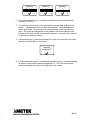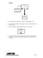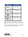
1
CAN-COMMUNICATOR (C-COM)
USER GUIDE
Rev A
Rev A
Table of Contents
DESCRIPTION ....................................................................................................... 4
SPECIFICATIONS .................................................................................................. 5
PHYSICAL CHARACTERISTICS........................................................................ 5
ENVIRONMENTAL CHARACTERISTICS........................................................... 5
ELECTRICAL CHARACTERISTICS ................................................................... 5
ELECTRICAL INPUTS ........................................................................................ 5
ELECTRICAL OUTPUTS .................................................................................... 5
DISPLAY CHARACTERISTICS .......................................................................... 5
ELECTRICAL CONNECTIONS........................................................................... 6
GAUGE DIMENSIONS........................................................................................ 6
PANEL CUT-OUT DIMENSIONS........................................................................ 6
STANDARD DISPLAY PARAMETERS .................................................................. 7
DATA PARAMETERS ......................................................................................... 7
POPUP WARNING MESSAGES ........................................................................ 7
SCREEN MENU OVERVIEW ................................................................................. 8
SCREEN MENU DETAIL........................................................................................ 9
POWER UP......................................................................................................... 9
DATA................................................................................................................. 10
DIAGNOSTICS AND WARNINGS .................................................................... 11
WARNINGS ................................................................................................... 11
DIAGNOSTICS – ACTIVE ............................................................................. 12
DIAGNOSTICS – STORED ........................................................................... 15
SETUP .............................................................................................................. 17
DATA ............................................................................................................. 17
WARNING ..................................................................................................... 19
UNITS............................................................................................................ 21
CONTRAST ................................................................................................... 22
BRIGHTNESS ............................................................................................... 23
POPUP MESSAGES......................................................................................... 26
Rev A
DESCRIPTION
The CAN-Communicator (C-COM) provides the advantages of a graphic display in
a compact, 2-inch gauge form factor. This rugged and versatile gauge can be
used exclusively, or as a compliment, to any existing instrumentation simply by
connecting it to an SAE J1939 (CAN) data bus. The gauge can display data and
diagnostics, both active and stored faults from the individual ECMs, directly from
the vehicle data bus.
There are 3 buttons for navigating the screens through an intuitive menu system,
displaying diagnostics, parametric data and popup warnings. Diagnostic
capabilities include both active and stored fault codes from the ECU. Data can be
viewed as a single parameter or as three parameters, which the user can scroll
through to view additional data. C-COM is also populated with popular warning
messages (pop-ups) to alert the user to conditions on the vehicle.
C-COM is designed for additional flexibility to the user. The setup menu screens
provide customization to the data line items and warning messages that can be
displayed. Warnings can also be set to provide an output for an external buzzer.
The setup menus allow for units to be switched to English or metric and set the
display contrast and brightness.
The backlit liquid crystal display (LCD) is 106 pixels wide and 56 pixels high,
providing clear, legible graphics. Backlighting can be controlled through the menu
or an external dimmer. A dead-fronted warning indicator is positioned above the
graphic display window and is capable of illuminating as an amber or red warning
for active fault codes and popup warnings, respectively.
C-COM is sealed to IP67 specifications both front and rear of the gauge and
operates from 9 to 32 volts DC. C-COM can also accept an analog input, as an
option to add a parameter for viewing. Included is a switch-to-ground output that
can be used to control an external annunciator, relay, or other device.
This user guide is intended to help you set up C-COM, understand product
features and navigate the menu system.
Rev A
SPECIFICATIONS
Physical Characteristics
Housing and bezel material: Chrome or Black polycarbonate ABS plastic
Connector: Single Deutsch DT06, polarized and locking
Environmental Characteristics
Temperature, humidity, shock, vibration, and salt spray: Meets or exceeds SAE
#J1455-1994-08
Operating Temperature: -20 to +85oC
Electrical Characteristics
Operating limits: 9 to 32 VDC, reverse polarity protected
Transient protection: Meets or exceeds SAE #J1455-1994-08
Electrical Inputs
Battery/ignition: 9 to 32 volts
Input current: 500 mA
Backlighting: Variable through dashlight dimmer control or through display menu
Data bus: SAE J1939 (CAN)
Electrical Outputs
Switch to ground: One, 500 mA
Display Characteristics
Type: Positive mode, transflective, LCD dot matrix, FSTN
Aperture size (inches): 1.21W × 0.64H
Pixel dimensions: 106 pixels wide, 56 pixels high
Viewing angle: 12:00
Backlight color: Standard is Amber (can be customized to any color)
Rev A
Electrical Connections
Gauge Dimensions
Panel Cut-Out Dimensions
Rev A
STANDARD DISPLAY PARAMETERS
DATA PARAMETERS
The following are the standard data parameters. Other data parameters broadcast on
J1939 data bus can be added as a custom system.
•
Vehicle Speed
•
Engine RPM
•
Engine Oil Pressure
•
Coolant Temperature
•
Engine Oil Temperature
•
Battery Voltage
•
Turbo Boost Pressure
•
Transmission Oil Temperature
•
Engine Hours
POPUP WARNING MESSAGES
The following are the standard popup warning messages. Other messages broadcast on
J1939 data bus can be added as a custom system.
•
Coolant Temperature
•
Engine Oil Pressure
•
Engine Oil Temperature
•
Transmission Temperature
•
Battery Voltage
•
Check Engine
•
Stop Engine
•
Check Transmission
Rev A
SCREEN MENU OVERVIEW
DATA
WARNINGS
DIAGNOSTICS
ACTIVE
STORED
SETUP
DATA
WARNINGS
UNITS
CONTRAST
BRIGHTNESS
VERSION
Rev A
SCREEN MENU DETAIL
POWER UP
Screen Displayed for 2
seconds
Screen Displayed for 2
seconds
DATA
1. When power is first applied to C-COM, the display will turn on all pixels for two
seconds.
2. The Ametek logo will then be displayed for two seconds.
3. Data screens are now displayed, unless a popup message(s) is active, which will
remain on the display until the condition goes away or the message is dismissed
with a button press.
Rev A
DATA
Speed
Speed
85 MPH
Tach
1200 RPM
Eng Oil
60 PSI
Display Next Data
Value
85 MPH
Display Next Data
Value
DIAGNOSTICS &
WARNINGS
DIAGNOSTICS &
WARNINGS
1. The first three data values will be displayed. Press the left button, corresponding
to the scroll prompt, to scroll through all of the data values. Data parameters in a
standard product include:
•
•
•
•
•
•
•
•
•
Vehicle Speed
Engine RPM
Engine Oil Pressure
Coolant Temperature
Engine Oil Temperature
Battery Voltage
Turbo Boost Pressure
Transmission Oil Temperature
Engine Hours
2. To view a single data value in a larger format, press the right button, corresponding
to the magnifier prompt. Data values can also be scrolled in this view. Press the
right button again, now corresponding to the demagnifier prompt, to display the
three data values.
3. Pressing the center button, corresponding to the warning prompt, from either data
view will change the display to Diagnostics and Warnings.
Rev A
DIAGNOSTICS AND WARNINGS
WARNINGS
No
Warnings
Warnings
Diagnostics
No Messages in
Warning List
Warnings Present
Diagnostics
STOP
ENGINE
Warnings
Long Press
Display Next
Warning
DATA
SETUP
DATA
1. Press the left button, corresponding to the scroll prompt, to select between
Warnings and Diagnostics.
2. Select Warnings by pressing the right button, corresponding to the check prompt.
3. If there are no warnings in the list, the display will read No Warnings. If there are
warnings present, the first Warning Message will be displayed. Press the left
button, scroll prompt, to view additional warning messages.
4. By pressing the center button, gauge prompt, will return to the Data screens. A
long-hold press of the center button, 2 seconds, will display the Setup menu
screens.
Rev A
DIAGNOSTICS AND WARNINGS
DIAGNOSTICS – ACTIVE
Diagnostics
Warnings
Warnings
Diagnostics
Long Press
DATA
SETUP
1. Press the left button, corresponding to the scroll prompt, to select between
Warnings and Diagnostics.
2. Select Diagnostics by pressing the right button, corresponding to the check
prompt.
Rev A
Diagnostics
Active
Stored
Long Press
DATA
SETUP
3. Select Active by pressing the left button, corresponding to the active prompt.
Pressing the center button, gauge prompt, will return to the Data screens. A longhold press of the center button, 2 seconds, will display the Setup menu screens.
No Faults
No Active Faults
Present
Active Faults Present
Source 0
Engine
Display Next
Source
4. If there are no active fault codes present, the display will read No Faults. If there
are fault codes present, the first source of fault codes will be displayed. Press the
left button, scroll prompt, to view additional sources. A center button press, back
arrow prompt, will return to the Diagnostics Active and Stored screen.
Rev A
Polling
Source 0
Polling Complete
Source 0
SPN ddd
FMI ddd
Display Next
Fault
5. Press the right button, magnifier prompt, to view the fault code details. The gauge
will begin polling the selected source and once it is complete will display the fault
code. The left button, scroll prompt, will scroll through all the active fault codes in
the current source.
6. By pressing the center button, back arrow prompt, will return to the Source
screens. A press of the right button, demagnifier prompt, will display the Source
screens also.
Rev A
DIAGNOSTICS AND WARNINGS
DIAGNOSTICS – STORED
Diagnostics
Active
Stored
Long Press
DATA
SETUP
1. Select Stored by pressing the right button, corresponding to the stored prompt.
Pressing the center button, gauge prompt, will return to the Data screens. A longhold press of the center button, 2 seconds, will display the Setup menu screens.
No Faults
Polling For
Stored Faults
No Stored Faults
Present
Polling Complete
Stored Faults Present
Source 0
Engine
Display Next
Source
2. The gauge will begin polling for stored faults. Upon completion, if there are no
stored faults present, the display will read No Faults. If there are fault codes
stored, the first source of fault codes will be displayed. Press the left button, scroll
prompt, to view additional sources. A center button press, back arrow prompt, will
return to the Diagnostics Active and Stored screen.
Rev A
Polling
Source 0
Polling Complete
Source 0
SPN ddd
FMI ddd
Display Next
Fault
3. Press the right button, magnifier prompt, to view the fault code details. The gauge
will begin polling the selected source and once it is complete will display the fault
code. The left button, scroll prompt, will scroll through all the active fault codes in
the current source.
4. By pressing the center button, back arrow prompt, will return to the Source
screens. A press of the right button, demagnifier prompt, will display the Source
screens also.
Rev A
SETUP
DATA
Data Setup
Display Next Setup
Screen
DIAGNOSTICS &
WARNINGS
1. A long-hold press of the center button, 2 seconds, in the Diagnostics and
Warnings screen, will display the Setup menu screens.
2. Press the left button, scroll prompt, to select the next Setup option, Warning
Setup.
3. By pressing the center button, warning prompt, will return to the Diagnostics
and Warnings screen.
4. Press the right button, magnifier prompt, to access the Data Setup menu.
Rev A
Speed MPH
Tach RPM
Eng Oil PSI
Speed MPH
Tach RPM
Eng Oil PSI
Display Next Data
Value
5. All of the standard data parameters will be listed with check marks next to
them, indicating that they are selected to display in the Data view. To deselect
a data parameter, press the right button, corresponding to the check mark
prompt. An X will now appear next to that data parameter.
6. By pressing the right button again, the data value will once again be selected
and have a check mark next to it.
7. Press the left button, scroll prompt, to scroll through each of the data
parameters.
8. The center button, back arrow prompt, will return to the Data Setup main
screen.
Rev A
WARNING
Warning Setup
Display Next Setup
Screen
DIAGNOSTICS &
WARNINGS
1. Press the left button, scroll prompt, to select the next Setup option, Units Setup.
2. By pressing the center button, warning prompt, will return to the Diagnostics and
Warnings screen.
3. Press the right button, magnifier prompt, to access the Warning Setup menu.
Rev A
ENGINE TEMP
ENGINE OIL
ENGINE OIL TEMP
Speed MPH
Tach RPM
Eng Oil PSI
Speed MPH
Tach RPM
Eng Oil PSI
Display Next
Warning Message
4. All of the standard warning messages will be listed with check marks next to them,
indicating that they are selected to display as Popup warning messages. To
deselect a warning, press the right button, corresponding to the check mark
prompt. An X will now appear next to that warning.
5. By pressing the right button again, the warning will have a check mark with a plus
sign, to indicate that the switch-to-ground output will be used to control an external
annunciator, relay or other device. Another press of the right button will select the
warning with a check mark.
6. Press the left button, scroll prompt, to scroll through each of the warnings.
7. The center button, back arrow prompt, will return to the Warning Setup main
screen.
Rev A
UNITS
Units Setup
Display Next Setup
Screen
DIAGNOSTICS &
WARNINGS
1. Press the left button, scroll prompt, to select the next Setup option, Contrast.
2. By pressing the center button, warning prompt, will return to the Diagnostics and
Warnings screen.
3. Press the right button, magnifier prompt, to access the Units Setup menu.
Units
English
Metric
Units
Metric
English
4. Press the left button, scroll prompt, to switch between English and metric units. To
select the unit, press the right button, check mark prompt. To cancel, press the
center button, cancel prompt. Each of these button presses will return to the Units
Setup main screen.
Rev A
CONTRAST
Contrast
Display Next Setup
Screen
DIAGNOSTICS &
WARNINGS
1. Press the left button, scroll prompt, to select the next Setup option, Brightness.
2. By pressing the center button, warning prompt, will return to the Diagnostics and
Warnings screen.
3. Press the right button, magnifier prompt, to access the Contrast menu.
Contrast
Contrast
+
Contrast
+
+
4. To increase the contrast, press the right button, corresponding to the plus sign
prompt. To decrease the contrast, press the left button, corresponding to the
minus sign prompt. The contrast will increase/decrease a half step with each
press. Pressing and holding either of these buttons will increase/decrease the
contrast by full steps and will continue until the button is released or has reached
its minimum or maximum setting.
5. A center button press, check mark prompt, will select the current contrast and
return to the Contrast main menu.
Rev A
BRIGHTNESS
Brightness
Display Next Setup
Screen
DIAGNOSTICS &
WARNINGS
1. Press the left button, scroll prompt, to select the next Setup option, Version.
2. By pressing the center button, warning prompt, will return to the Diagnostics and
Warnings screen.
3. Press the right button, magnifier prompt, to access the Brightness menu.
Backlight Control
Internal
External
Backlight Control
External
Internal
5. Press the left button, scroll prompt, to choose between internal or external
backlight control. To select the control type, press the right button, check mark
prompt. To cancel, press the center button, cancel prompt, which will return to the
Brightness main screen.
Rev A
Intensity
Intensity
+
Intensity
+
+
6. If Internal backlight control is selected, the backlight intensity can be adjusted
manually in this view.
7. To increase the intensity, press the right button, corresponding to the plus sign
prompt. To decrease the intensity, press the left button, corresponding to the
minus sign prompt. The intensity will increase/decrease a half step with each
press. Pressing and holding either of these buttons will increase/decrease the
intensity by full steps and will continue until the button is released or has reached
its minimum or maximum setting.
8. A center button press, check mark prompt, will select the current intensity setting
and return to the Brightness main menu.
Intensity
set by pin 3
9. If External backlight control is selected, the backlight intensity is controlled through
an external source and must be connected to pin 3 . Press the center button,
check mark prompt, will return to the Brightness main screen.
Rev A
VERSION
Version
Display Next Setup
Screen
DIAGNOSTICS &
WARNINGS
1. Press the left button, scroll prompt, to select the next Setup option, Data.
2. By pressing the center button, warning prompt, will return to the Diagnostics and
Warnings screen.
3. Press the right button, magnifier prompt, to access the Version menu.
SW: 2.0
CFG: 2.0
4. The code and configuration versions programmed into the C-COM gauge will be
displayed. Press the center button, back arrow prompt, to return to the Version
main screen.
Rev A
POPUP MESSAGES
MESSAGE
ACTIVATION
STOP
ENGINE
PGN = 65,226 (DM1), SA = 0
SPN = Any, FMI = Any
Red Stop Lamp On
CHECK
ENGINE
PGN = 65,226 (DM1), SA = 0
SPN = Any, FMI = Any
Amber Warning Lamp On
CHECK
TRANS
PGN = 65,226 (DM1), SA = 3
SPN = Any, FMI = Any
Amber Warning Lamp On
ENGINE
TEMP
225 oF
PGN = 65,226 (DM1), SA = 0,
SPN = 110, FMI = 0,15,16
10-22-08
MESSAGE
ACTIVATION
ENGINE
OIL
25 PSI
PGN = 65,226 (DM1), SA = 0,
SPN = 100, FMI = 1,17,18
ENGINE
OIL TEMP
275 oF
PGN = 65,226 (DM1), SA = 0,
SPN = 175, FMI = 0,15,16
TRANS
TEMP
325 oF
PGN = 65,226 (DM1), SA = 3,
SPN = 177, FMI = 0,15,16
BATTERY
WARNING
10.2 V
PGN = 65,226 (DM1), SA = 0,
SPN = 168, FMI = 0,15,16, 1,17,18
The table above outlines the pop-up warning messages C-COM will display when an
activation message is received from the J1939 databus. These messages will replace
whatever is currently on the display until either the condition goes away or the message is
dismissed.
Messages can be dismissed via left, center or right button press. Once a pop up message
is dismissed via key press, it does not activate again during the current ignition cycle
unless the trigger condition goes inactive and then active again.
END OF DOCUMENT
10-22-08