1
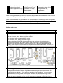
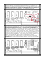
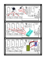
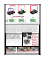
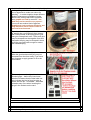
Apple 1 ROMcard
User manual
and
Installation
copyright by James Edward Harro Walsh
edited Spring 2013
General Information
The Apple 1 ROMcard was designed to not only expand the usage of the Apple 1 and it´s different
kinds of Replications like the MIMEO from Mike Willegal, the NEWTON from Michael NG, the
former Obtronix as well as the original Apple 1 from Apple Computers as it was designed from
Steve Wozniak, but it was also created to simplify the life of the users of this systems.
In normal operation all of this systems must immediately after the startup a programm or Basic
become loaded from tape if the user does not want to work in machinecode….
This is the result from the limited RAM memory on the mainboard and the also very limited
available ROM that only contains the very compressed WOZ-Monitor.
Using this ROMcard permits the user to make own EPROMS with content that must not be loaded
from tape and stays resident available in the system, like a BASIC in the Eprom or a editor or a
disassembler for the 6502 and disassembling tools or even if wanted some games that might be
started immediately after switching the systempower on. If the user has a set of different EPROMs
he/she might just even change instantly the use of the computer by exchanging the used EPROM.
In this case it´s strong recommended to supply the card with so called Zero-force sockets where
the used EPROM is locked into the socket with a lever. In such cases the EPROMS may just be
changed by switching off the power – and then just switching on the power again after the change
of the EPROM has been performed. Another use ( like it is the aim of the designer of the card ) is
to expand the Apple 1 with the ability of advanced graphicspower. The original Apple 1 only
performs graphics with ASCII and therefor is limited. If leaving machinecode-routines and graphicsymbols like sprites in an EPROM advanced graphics will become available.
At the other hand it was one of the goals of the design to keep the so called authenticity with the
basic system itself and use only parts that have also been available within the following 4 to 5
years after the introduction of the Apple 1 to the market. The designer is rather sure, that if the
Apple II would have not been introduced that fast into the market the amount of Apple 1 computers
would have participated from the same success as the Apple II.
Another goal of the card was to keep the design open as a multipurpose-card and to enable the
user to have freedom of choice how to use his card…. As library of different user programs in
EPROMs or as development system for own creations on the Apple 1.
In those years the 2708 ( sometimes also 2508 ) as well as the 2716 ( sometimes the 2516 ) have
been the common Eprom-chips. Besides also the 6116 as static RAM chip became available. This
chip is rather interesting because it is rather similar with the 2716 EPROM and it can be just called
a “instant-testing” version for that EPROM chips…. Therefore the use of this 6116 static-RAM
chips is permitted too…. This gives the user the power to first test the software planned to become
resident in a chip in the static RAM first and if the software runs well without mistakes – then
program the software in a EPROM and then use that software instantly from the EPROM.
Another advantage of the 6116 static Ram is that if it is buffered with a NiCAD battery – its content
becomes nearly really static for several days and the content is not lost after the computer is
powered off …. The user might switch on the computer several days later and continue the work
on the content in the RAM without the need to reload that contents from the tape…. Only if the
work on the software is interrupted for more than a week, it is recommended to save the content to
tape to preserve the contents.
Of course the same goal could have been solved using modern RAMchips with less power
consumption like NOVRAMs – but that would have not matched with the preliminary goal of
authenticity as explained above…. The user is forced to accept at least some kind of “disabilities”
given by the standards of those days….. but at the other hand there is no reason to not unleash
the full power the Apple 1 could have reached in that days, if more time would have been given to
the system before introducing its follow-up the Apple II.
To keep the multifunctionality of the card within the goal the card provides the ability to place up to
4 sockets on the card. Each of the 4 sockets has its own lines and the user may start by first just
working with one socket and later he might continue by inserting and soldering additional sockets
for expanded usage. Therefore on the card the parts related to each socket are indicated by their
labels printed on the card. Some further information is given later in this manual too…..
Another advantage of this concept is that each socket may be used with its own chip –
independently from the chip used in the neighbour socket. So every socket may be used
individually.
Respective to the fact that modern EPROM-programmers mostly don´t permit to program 2708 or
2716 chips ( neither 2508 or 2516 ) the design was also expanded to integrate also the ability to
program those chips on the card.
Within this summer 2013 a program will be released that permits to program the chips “in the card”.
To make the use for “non-technical” users easy I will release this program as EPROM-file and as
program to type in at the prompt. There will be instructions given, how to transfer this program into
an EPROM and there after it will be as simple as inserting that EPROM in one of the free sockets
and just starting with the programming sequence.
Another aspect of the multifunctionality is the fast that the 6502 Processor is able to handle all
adresses up to 65536 Bytes. On the mainboard only 2 rows are used with each normally 4 Kilobyte
of RAM ( together 8 kilobyte ) and another 4 kilobyte of ROM is used by the ROM in the system
that contains the WOZ-Monitor. So only 12 kB of the 64 kByte are used by the basic system with
up to 52 kByte of available space for free use. If the 4 kB which are requested from the Apple
Cassette Interface are subtracted from that amount, then still there are 48 kB free space are
available.
At the other hand its rather normal to expect that such a system will be expanded first with
additional memory and in those days the largest normal available chips have been the 4116 chips
and each row of such chips would have expanded the memory with additional 16kB of RAM.
Assuming that in the following years the follow-up system of the Apple II system was rather often
expanded with 2 rows of the available chips ( in that later days that have been the 4164 and the
common upgrade had been 128 kB of RAM ).
It therefore is not uncommon to guess that in Apple I days it would have only needed few more
months to introduce a card with additional 2 rows of 4116 chips and upgrading the computer with
additional 32 kB of RAM. In such a case the system would have had all together 40 kB of RAM
leaving the space from 40 kB to 60 kB still free. Subtracting again the 4 kB of the ACI ( Apple
Cassette Interface ) too and the 4 kB used by the WOZ-Monitor in the ROM on the mainboard
there still would have been the area from 44 kB to 60 kB free for other usage.
Therefore this ROMcard is designed to permit this entire space to be used. Each socket is
permitted to be set individually in 4 kB steps with 4 adresses within that area and interleaved in
that way that from socket 1 to socket 4 that each addressing range decreases by 4 kB.
So the addressing range from socket 1 is selectable from 60kB down to 48 kB and the socket 2
can be set from 56kB to 44 kB, socket 3 can be set from 52 kB to 40 kB and socket 4 can be set
from 48 kB to 36 kB. If using 6116 static RAM chips that addressing range can be set to just add
up directly after the normal RAM.
But instead of setting the adressing range like at the ACI with a wire bridge on the mainboard instead the ROMcard permits to select the addressing ranges with a own DIP-switch for each
socket on the ROMcard without touching the mainboard.
Installation
Displaying the sections of the Card
The light red to light violet areas are dependent to the
sockets and each section for the individual socket is
indicated by its own color. Be aware that each socket
has 2 sections: the socket section and the adressswitch section and both with same color. So you may
only populate one socketwith 2 sections – but with one
color.
The sections are
indicated
by the
individual
colors
The light yellow area is
requested to stabilize the
The dark green area is
only requested to control
The light blue area
is relevant to the adressing on the card
and must be populated
in any case.
The light
brown area
is related
to backup
power of
6116 RAM.
This section
must only
be populated if 6116
chips are
used.
The light green area is
only important if the card
voltages for the card
itself and therefore it
must be populated in any
case.
the programming voltage
by switching it on or off
by software – it must
only be populated if the
card is used for
programming chips.
will be used for
programming chips. This
area generates the
voltage requested for
programming.
Please recognize that there are sections that must be populated and some areas which must not
be populated. The precise infos are given in the table above.
Please recognize that in the picture above the colors are used in another way than in the graphic
displayed later, where the typ of components are indicated by color ( red for active components like
ICs or transisitors, brown for resistors, blue for capacitors and green for switches….. ).
Building up the Card
First step: Resistors
There are 4 kinds of resistors with the following explained colorcodes:
100 ohm = brown, black, brown and silver or gold
1k = brown, black, red and silver or gold
10 k = brown, black, orange and silver or gold
15 k = brown, green, orange and silver or gold
bend the wires carefully by 90 degrees and insert the resistors in the related holes –
cover the top of the card with carton and fix it with rubberrings to prevent resistors from
slipping out of their place and turn card to soldering side ( that’s the side without white
printing ) and solder the resistors with 300 degrees Celsius and solderinglead. Carefully cut
the wires above of the soldering spot.
Second step: Diodes
there are different kinds of diodes. All diodes have two important point to recognize: the
printing on the case that indicate the type of diode and a ring around the case that indicates
on which side the cathode is. You must pay attention to both markings. The typ must be
isentified before inserting in the correct place – but also very important the ring which
indicates in which kind of orientation the diode must be inserted in that place ! Inserting
diodes with wrong orientation of the ring will cause severe damage to the electronics so
please check twice the correct orientation before proceeding to the soldering task. Fix the
components again with carton and rubberrings to avoid slipping out of components when
turning card to the soldering side. Before soldering one very important additional remark: this
components are very temperature sensitive ! So it´s upmost important to keep temperature of
solderingiron in correct range and to NOT exceed soldering time more than neccessary ! The
solderpoint must be accurate and safe soldered - but the diode may not be fried!
Third step: sockets
When inserting the sockets please take a closer view to that components. Its impossible to list
here all different kinds of indicators that show at which side the pi1 should be located – that
differs from one manufacturer to the next one….. but in most cases the sockets have a
special marking to show where pin1 is located ( notch , arrow or similar ) – so please use that
marking and place the socket with correct orientation. After tha socket is soldered in place
there will be no other indication than the graphics in this manual. On the PCB pin 1 is always
indicated by a square soldering pad instead of the round soldering pad used at the other pins.
Remark to the choice of the sockets: if you want to have high reliability the choice will be to
use precesion-sockets with goldplating…. If you want the card to match the standards of old
cards you should at least check that all contacts are clean and without oxidation….
For the sockets used at the “Typselect” places it is recommended to use round precision
sockets because this plugs may often be changed and cheap sockets may soon get untight /
bad contact……
Forth step: switches
Insert switches on their proposed places. The picture shows different kinds of usable
switches. There is only one slide switch - which should be placed that way, that the slide can
be pushed up or down from the borderside of the card because later, when the NiCAD battery
is soldered in place, there will not be any chance to operate that switch from that other side !
Same is valid if the DIL-switches have sidelevers like in the left side of the picture ! Such
switches should be inserted that way that the levers show towards the side with printing and
with no components. Fix the position like done in the previous steps and turn card around and
solder the switches carefully.
Fifth step: capacitors
The assembly of the capacitors can be split in 2 tasks…. The first task is simple: adding the
ceramic capacitors with the value of 100nF is rather simple – there is no need to care about
the orientation…. The second task is more difficult: the electrolytic capacitors… the have
different values and the have different kinds of outwires – a minus-pol and a plus-pol…..
again the indicator for that pols are different from company to company – but in most cases
the are indicated by a stripe at the outside of the case with a minus-sign printed on it –like the
example picture blended in below. When inserting the 5 electrolytic-capacitors it is very
important to keep care about the polarity indicated by “+” and “-“ signs in the drawing below.
Be sure that the plus-pol wire is inserted at the correct side otherwise capacitors will blow up (
explode ) when power is connected – this will surely damage the electronics on the board.
After examining that capacitors are inserted correct – again the components should be fixed
in position like in earlier tasks , then turn around the card and carry out the duty to solder the
components carefully and cut off the remaining wires.
Sixth step: ICs and transistors
Seventh step: Zero force sockets
Eighth step: NiCAD Battery
Ninth step: Making the socketselection blocks
The pictures above show how the socketselectionplugs must be wired. It is highly
recommended to use precision sockets. They have round socketfeet that will fit perfectly
into the precisionsockets that are to be used on the card. The reason for using precision
sockets is not only good contact but also better changeability if the plugs are changed in
place because the IC´s on the card are changed. Of course you might leave the plugs
thereafter just as thay have been wired …. But then you must know which kind of plug is to
be used with which kind of IC. Alternate it might be more easy to treat the sockets as
shown in the following section and covering them with a 2k-glue top that might be signed to
indicate which type of plug it is.
First of all in that case a negativform will be
needed, where the plugs later after wiring
can be dumped in. I´ve used a part of a
storage tube for EPROM-ICs. Alternate
such a form may be made with model
plaster by just dunking 14 pin socket in the
hardening material. Remember that it later
will be important to cover each time the
form inside with oil or grease to prevent the
plug and glue from sticking to the form.
The pictures show examples of such plugs. Before dunking them in 2k glue the wires
should be flattened down like shown in the right picture.
Artist painting with oil are common with the
use of pigments to make own colors for
painting…. In artists supplies shops different
kinds of pigments are available to make
black color. Among that kind of pigments
also graphit and coal is common – but
both may not be used for our pupose !
You must use another kind of pigment.
Graphit and coal conducts electricity and
may therefore not be used in order to
prevent from shortcuts !
If you have found a pigment other than coal
or graphit then you might mix them among
the 2 components of the epoxyglue to give
that glue a deep black color. Then such glue
may be dumped into the negative form and
thereafter the plug may be dumped in there
to till the glue gets hard enough to extract
the hardened plug.
This task is shown in the right picture.
After the glue hardened the plug may be
extracted from the form easily, if you have
not forgotten to apply grease of oil to the
form before.
The next picture at the right side shows the
finished plugs – before they have been
labelled. Be aware that the label shall not
only indicate the kind of plug but also at
which side the pin 1 is located – otherwise
mistakes may occur when inserting the
plugs in the sockets on the card.
Tenth step: controlling soldering side
Eleventh step: Compare with pictures of examples
12th step: Testing voltages
Recommended settings for the Apple 1 ROMcard


![RTX4100 Wi-Fi Module User Guide WSAB Docking Station [UG7]](http://vs1.manualzilla.com/store/data/006886306_1-a44ab0f4a9043ebd3739376f36e6f1b4-150x150.png)