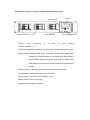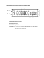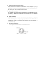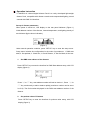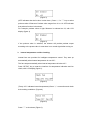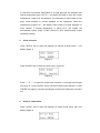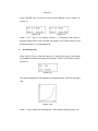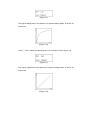
1
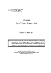
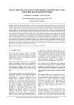
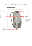
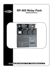
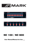
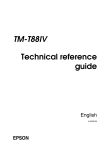
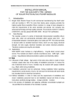
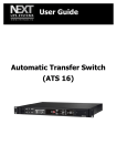
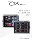
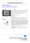
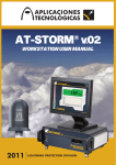
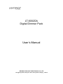
LT-6002DA
Digital Dimmer Pack
User’s Manual
BEIJING STARLIGHT ELECTRONICS CO.,LTD
7 Xingguang Road, Xihongmen Town, Daxing District, Beijing
100076
Transportation and Storage Conditions
Delivery - unpacking
Generalities - Safety
Important Notice for Cables
Product Features
Technique Parameters (Product Characteristics)
Installation Requirements
Instruction for front panel
Instruction for rear panel
Cable connection
Operation Instruction
Setup of dimmer parameters
Various check, protection and restore methods
Transportation and Storage Conditions
Severe vibration and collision should be avoided to prevent damage in transportation.
Protection against rain and snow should be provided in transportation and storage.
Storage place should be kept dry, without any conspicuous pollution by erosive,
flammable gas, or water vapor, etc.
Stack quantity should be kept within limit to prevent damage.
Temperature range for transportation and storage: 25℃~+55℃
Delivery – unpacking
®
Upon receipt of LIGHTSPACE products, make sure that the packaging is unopened,
and examine your equipment carefully for completeness;
Strict inspection shall be conducted to confirm perfect condition of any equipment
before leaving the factory.
If any damage is detected, contact relative parties and keep record.
Verify if delivered products are in conformity with delivery list and the specification of
the product series.
Check if the quantity and equipment model are in conformity with the delivery notice;
In the event of any error, contact the shipper immediately to clarify the situation until
receiving reply with satisfaction.
If no error is detected, put the product back in the packing and store it at a suitable
place for final installation.
Generalities – Safety
LT-6002DA six channels digital dimmer Pack is in compliance with Europe safety
standard EN60950-1:2006 and EN60204-1:2006. It is categorized as Class I
equipment, designed and produced in accordance with relevant safety standards,
and provided with compulsory safety grounding by local standards. To prevent any
risk of electric shock, do not remove any cover or part of the enclosure. Access to
internal parts is not required for normal operation. If damaged, equipment must be
repaired and maintained by professional service personnel exclusively. Disconnect
from external power supply prior to the opening for inspection or maintenance.
WARNING!
LETHAL VOLTAGES ARE PRESENT INSIDE! PAY ATTENTION TO
YOUR SAFETY! INSTALLATION, DEBUG, AND MAINTENANCE MUST
BE OPERATED BY PROFESSIONAL PERSONNEL!
EVERY USER SHOULD READ THE MANUAL CAREFULLY BEFORE
OPREATION AND COMPLY WITH THE REQUIREMENTS.
Important Notice for Cables
Power supply cables and connectors are important parts of the safety means for the
equipment.
z
A main circuit breaker, or fuses shall be provided at the power supply terminal of
the cables to cut off the power supply; never touch or contact the power cables;
z
Ensure the cable and the connectors are intact, confirm that no damage to the
cables exists at each installation and regular checks;
z
Do not connect the cables with the signal lines.
Product Features
Fully digital dimming, 6×2kW dimming output
With DMX-512 signal input in accordance with international universal
protocol, initial address can be set up at random (1 – 512).
LCD digital indication in English
Professional filter with a rising slope of 300us is provided for each
channel to reduce audio and video interference.
Provided with filaments preheating function, MCB overload and
short-circuit protection.
Intelligent control of fans and over-temperature alarming
Dimensions(mm): 483(width) ×88(height) ×375(depth)
Weight: 9kg
Integrated design, light weight, easy maintenance
Technique Parameters (Product Characteristics)
Control electronics: fully digital, microprocessor controlled;
Power Ratings: dimmers rated for continuous duty: 6 ×2 kW;
Max power of the whole dimmer Pack is 12kW;
Operation environment: places with temperature ranging from 0~40℃,
relative
humidity
at
25℃
less
than
90%,
no
condensation, atmospheric pressure less than 106kP,
no erosive or flammable gas and heavy dust, natural
ventilation.
Power supply: 3NPE 400V 50HZ TN-S three phase five wire system;
Power supply voltage range: 230V±10%;
Rated supply current: Supplied by star system 3N~ with PE; 20A per phase at
230V;
Dimmer protection: MCB mini breaker (Max. breaking capacity 6000A);
Control signal protocol: DMX-512/1990 USITT
Response time: DMX ≤50ms
Dimmer resolution: 256 steps
Power semiconductors: anti-parallel thyristors;
Min. load per dimmer: ≥60W
DC component in output voltage: below 1V in rated load range;
Types of load: incandescent lamps, tungsten halogen lamps, and transformer-led
low voltage lamps;
Color code for supply cable: brown and/or black for phases L1, L2, L3;
Blue for neutral N;
Yellow/green for earth PE;
EMC standard: EMC55015
Safety standard: EN60204-1:2006
EN60950-1:2006
Types of sockets: PHOENIX terminal, SOCEPEX 19 pin socket, Europe
SCHUCKO socket, and 32A three pin lighting dedicated socket
with earthing are available for client selection.
Protection:
Protection for each dimmer by MCB (breaking capacity 6kA ) to ensure safe
operation of system under rated conditions;
Cooling: intelligent temperature control fans, and ventilation outlets on both sides.
Installation requirements
Warning!!!
LETHAL VOLTAGES ARE PRESENT INSIDE! DISCONNECT FROM THE
POWER SUPPLY PRIOR TO INSPECTION OR MAINTENANCE!
INSTALLATION, DEBUG, AND MAINTENANCE MUST BE OPERATED BY
PROFESSIONAL PERSONNEL!
Operation environment of the dimmer Pack should meet the requirements to ensure
safe and reliable operation of the product.
Slight squeaks could be generated by dimmer operation. Please confirm if the noise is
allowed by the installation environment.
As professional equipment, LT-6002DA must be installed and debugged by professional
personnel.
Dimensions(mm): 483(width)×88(height)×375(depth)
Power supply: 3NPE 400V 50HZ TN-S three phase five wire system;
Signal protocol: DMX512/1990 USITT
Installation methods: independently or integrated in cabinet or flight case.
Configuration of the front panel is shown in the following figure.
Display
Function keys
MCB
Dimmer indicator
Function
keys:
consisting
DMX indicator
of
4
keys
Three phase indicators
in
total,
namely
“SETUP”,“ENTER”,“△”,“▽”.
Three phase indicators: indicating any phase loss of three phase power supply
DMX indicator: indicating DMX signal connection. Without DMX signal, DMX
indicator is off; DMX indicator is in red flash when DMX signal is
normal; DMX indicator turns green upon receipt of signal, while
initial address of this Pack is beyond control range of the dimmer
console.
Dimmer indicator: indicating lighting density of each dimmer channel.
Circuit breaker: overload and short-circuit protection.
Single control:
control of a single dimmer output.
Master control: control of all output.
Display: setup and status indication.
Configuration of the rear panel is shown in the following figure.
Load terminal:32A three pin lighting dedicated socket
DMX OUT
L
DMX IN
N
PE
L1 L2 L3 N PE
POWER INPUT
Load terminal: connecting luminaries.
DMX IN:DMX Signal input
DMX OUT:DMX Signal output
POWER INPUT:L1, L2, L3, N, PE correspond with three phase power input, neutral,
and protective earth respectively.
Power supply connection
Warning!!!
Please do not open the cover to prevent electric shock.
If damaged, equipment must be repaired and maintained by professional service
personnel exclusively. Disconnect from the power supply prior to the opening for
inspection or maintenance.
A.
Type of main supply network
⑴
The standard LT-6002DA is suitable for a three phase 3NPE 400V 50Hz , TN-S
system (three phase wires + Neutral wire + earth wire);
⑵
The rated voltage between phase and Neutral is 230V;
⑶
Power supply voltage range: 230V±10%;
⑷
LT-6002DA can be operated on a single phase supply.
⑸
For any doubt, consult relevant electrician or utility company;
B. Cable connection requirements
⑴
LT-6002DA and its supply cable must be adequately protected against overload
and short-circuit by the installation; verify the current edition of the applicable
wiring regulations.
⑵
All connections should be performed by qualified electricians;
⑶
Copper cable with minimum size of 10mm2 is recommended for power supply
connection;
⑷
The color code is blue for Neutral wire (N) and yellow/green for PE;
⑸
The diameter of the Neutral wire must be larger than that of the phases by one
order; reduction of the diameter of the Neutral wires is dangerous and strictly
prohibited;
⑹
The supply cable should be sized for the rating of LT-6002DA;
⑺
Cables under the current ratings are not allowed.
Warning!!!
BEFORE ENEGIZING, MAKE SURE THAT NO
SHORT-CIRCUIT AT LOAD SIDE IS FOUND, AND N AND PE
WIRE ARE RELIABLY CONNECTED!!!
C.
Input connection of main power supply
Three phase lines are connected to “POWR INPUT” on the rear panel, L1, L2, L3
terminal are connected with corresponding power source line, N with Neutral line, PE
with earthing wire. Refer to the figure of the rear panel.
D.
Signal cable connection:
The signal line from dimmer console or last dimmer is connected to XLR connector
“IN” labeled as “DMX512” on the rear panel, XLR connector “OUT" is for connection
of the next dimmer.
E.
Output connection:
Load terminals are for connection with luminaries (take 32A three pin dedicated
socket with earthing as an example, its upper pin is connected with the phase line of
luminaries, the middle pin is connected with the N line, and the bottom pin is
connected with PE).
F.
DMX interface Instruction
It is in compliance with international standard DMX512/1990.
Operation Instruction
LT-6002DA six channel digital dimmer Pack is a newly developed light-weight
dimmer Pack, compatible with dimmer console and computerized lighting control
console with DMX-512 interface.
Set-up of dimmer parameters
When power is turned on, LCD display on the rear panel indicates: (Figure 1)
initial address number of the dimmer, internal temperature, and lighting density of
each dimmer (light column indication).
(Figure 1)
Under normal operation condition, press “SETUP” key to enter the setup menu.
Setup menu includes six configurations in the order of precedence: 1. DMX start
addr; 2. Set preheat; 3. Check fan; 4. Check Dimmer; 5. Set Out Mode; 6 Set Law.
1.
Set DMX start address of the dimmer:
Press “SETUP” key to enter the interface for DMX Start address setup, with LCD
display (figure 2)
(Figure 2)
Press “△”or “▽” key, start address number will add or deduct 1; Press
“△”or
“▽” key continuously to add or deduct rapidly (maximum number can be set to
be 512). The final number displayed is the DMX start address number of the
dimmer.
2.
Set preheat value of filaments
Press “SETUP key to enter the interface for preheat value setup, with LCD
display (figure 3)
(Figure 3)
(OFF indicates that the function is shut down.) Press “△”or “▽” key to select
preheat value of filaments. Preheat value ranges from 01 to 10. OFF indicates
that preheat function is shut down.
For example: preheat value of light filaments is selected as 02, with LCD
display (figure 4)
(Figure 4)
If the preheat value is selected, the dimmer will provide preheat output
according to the preset value in case there is no control signal after turning on.
3.
Internal temperature and fan checking:
Internal fans are provided for intelligent temperature control. They start up
automatically when internal temperature is over 55℃.
The fans stop automatically when internal temperature is below 45℃.
Press “SETUP” key to enter the interface for temperature indication and fan
check, with LCD display (figure 5).
(Figure 5)
(Temp: 29℃ indicates internal temperature) Press “△” to start fans and check
their working conditions. (Figure 6)
(Figure 6)
Press "▽” to shut down (Figure 5);
In case that environment temperature is so high that fans are damaged and
internal temperature gets over 75℃, the display will flash to show the current
temperature. Under such circumstance, it is necessary to reduce load or shut
down some dimmers to prevent damage on the equipment; When the
temperature is below 75℃, the display returns back to normal indication of
Pack number. If internal temperature is above 80℃, the system will
automatically reduce output of each channel by 50% (Direct-through output
remains the same).
4.
Check channels:
Press "SETUP” key to enter the interface for dimmer channel check, LCD
display (figure 7)
(Figure 7)
Press “ENTER” key to enter the check menu. (Figure 8)
(Figure 8)
Press “△” or “▽” to adjust the output level of dimmer 1, the output level ranges
from 00 to FL. Press “ENTER” key to check the output level of dimmer 2. Press
“ENTER” key again to continue checking the output level of dimmers 3 to 6 and
ALL.
5.
Setup of output mode:
Press “SETUP” key to enter the interface for output mode setup, with LCD
display (figure 9)
(Figure 9)
Press “ENTER” key to enter the output mode selection menu. (Figure 10,
Figure 11)
(Figure 10)
( Figure 11)
Press “△”or“▽”key to set dimmer channel 1 to switching mode (SW) or
dimming mode (DIM). Press “ENTER” key again to set output mode for next
dimmer channel (2 ~ 6) and all dimmers.
6.
Set dimming law:
Press “SETUP” key to enter the interface for dimming law setup. Four modes
are available for different dimming requirements. When LCD indicates “Gently”
(figure 12)
(Figure 12)
The output voltage level of the dimmer is increasing slowly, as shown by Figure
12A.
(Figure 12A)
Press”▽” key to select next dimming law, LCD indicates “Square” (figure 13)
(Figure 13)
The output voltage level of the dimmer is at square working status, as shown by
Figure 13A
(Figure 13A)
Press”▽” key to select next dimming law, LCD indicates “Linear” (figure 14)
(Figure 14)
The output voltage level of the dimmer is at linear working status, as shown by
Figure 14A
(Figure 14A)
Press”▽” key to select next dimming law, LCD indicates “Normal” (figure 15)
(Figure 15)
The output voltage level of the dimmer is at S curve status, as shown by Figure
15A
(Figure 15A)
Various check, protection, restore methods
Warning!!!
HIGH VOLTAGES ARE PRESENT INSIDE! DANGER!!! PAY
ATTENTION TO YOUR SAFETY!
INSTALLATION, DEBUG, AND MAINTENANCE MUST BE
OPERATED BY PROFESSIONAL PERSONNEL!
A.
To prevent electric shock please do not open the cover. In case of any damage to
equipment, inspection or maintenance shall be conducted by professional
personnel. Make sure power supply is disconnected before inspection and
maintenance.
B. Check main supply voltage before connecting equipment. If above the rated
voltage, internal control module may be damaged.
C. If lighting density of a dimmer channel cannot return to zero, and can be increased
by dimmer console, please check if the preheat function are set zero.
D.
If luminaries are normally off without control, while dimmer indicator indicates
normal, please check if circuit breakers are in open position or overloaded.
E.
If luminaries is normally on without control,while dimmer indicator indicates normal,
rectifier or other control modules may be damaged.
F.
If DMX indictor indicates abnormal condition, please check if the communication
connection is correct and if the dimmer console is working normal.
G. If phase line indicator is off, please check if the three phase lines are connected
correctly.
H.
In case of abnormal switch-off of MCB: close the switch again to check if the circuit
is electrified. If not, a short circuit shall exist, and then check the circuit; If MCB trips
again after being closed for some time, please check if an overload exists.
Check working condition of fans regularly.
I.
Notice:
⑴
Contact our company for maintenance, which should be carried out following the
guidance of professional engineers;
⑵
Since lethal voltage is present in the equipment, repair shall be conducted by
trained professionals;
⑶
Disconnect external power supply before opening the cover;
⑷
Disconnect external power supply before changing fuses F1A (5 x 20 mm) on
power supply board; thorough check around fuses should be made to detect
damage to fuses and possible malfunction of other components.
⑸
Contact the supplier if components are to be changed.
User's Manual for LT-6002DA Digital Dimmer Pack, Second Edition, 2009
BEIJING STARLIGHT ELECTRONICS CO., LTD
Copy right of Starlight Electronics Co., subject to change without prior notice.
BEIJING STARLIGHT ELECTRONICS CO.,LTD
7 Xingguang Road, Xihongmen Town, Daxing District, Beijing 100076
Tel: 010-60259548
FAX:010-60259757
60259546
E-mail: [email protected]
http://www.lightspace.com.cn
please contacts our company for technique support.