1
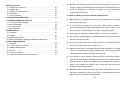
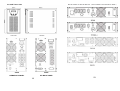
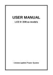
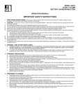
USER’S MANUAL
ON-LINE UPS
1-10KVA
Uninterruptible Power Supply
V2006-1.0
10-2 6K/10K
10-2-1 RS232 Interface
The following is the pin assignment and description of DB-9 connector.
Pin #
Description
I/O
2
TXD
Output
3
RXD
Input
5
GND
Input
10-2-2 AS400 Interface (For 6K/10K Optional)
Except for the communication protocol as mentioned above, this series UPS
has AS400 card (an optional accessory) for AS400 communication protocol .
Please contact your local distributor for details. The following is the pin
assignment and description of DB-9 connector in AS400 card.
Description
I/O
UPS Fail
Summary
Alarm
Output
3
GND
Input
4
Remote
Shutdown
Input
5
Common
Input
6
Bypass
7
Pin #
1
2
Output
Output
Figure 10.2: DB-9 Interface of AS400
Battery Low
Output
communication protocol
8
UPS ON
Output
9
Line Loss
Output
43
10. COMPUTER INTERFACE
CONTENTS
10-1 1k/2k/3k
10-1-1 Communication Interface
The communication interface (DB9 port) on the back of the UPS may be
connected to a host computer. The port provides RS-232 for monitoring
software.
The UPS communicates with the computer by sending out RS-232 data
streams to one of the serial ports. By this method the user is able to monitor the
following parameters.
Input Voltage
Indicates the present input voltage to the UPS
system when AC power is present.
Output Voltage
Indicates the present output voltage of the UPS.
AC Frequency
Indicates the actual output frequency of the UPS.
Battery Voltage
Temperature
Indicates the present DC voltage of the UPS
battery.
Indicates the actual temperature inside the UPS.
10-1-2 DB9 PIN Assignment
The PIN 2: RS232 RXD, PIN 3: RS232 TXD, and PIN 5: GND. The other PINs
have no function.
DB9 INTERFACE CONNECTOR
42
1. INTRODUCTION
1-1 General Description …………………………………………………..
1-2 Key Features ……………..……………………………………………
1-3 Important Notices ……………………………………………………..
1-4 The Meanings Of All The Initial Letter……..….……………………..
1-5 Operating Environment………………………………………………..
2. SAFETY
2-1 Transporting………. …………………………………………………..
2-2 Positioning….……………..……………………………………………
2-3 Installation……….……………………………………………………..
2-4 Operation……………………………………..….……………………..
2-5 Maintenance And Service……..………………………………….…..
3. CONNECT THE UPS AND ITS APPLICATION
3-1 1K/2K/3K………………………………………………………………..
3-1-1 Unpacking And Inspection For 1K/2K/3K………………………...
3-1-2 Input & Output Connection.………………………………………..
3-2 6K/10K………………………………………………………………….
3-2-1 Unpacking And Inspection For 6K(L)/10K(L)......…………………
3-2-2 Input & Output Connection…………………………………………
3-2-3 Connection Procedure For Long Backup Time Model…………..
3-2-4 Connection Procedure For Parallel Redundancy Mode………...
4. SYSTEM DESCRIPTION
4-1 Front Panel Description………………………………………….……
4-2 Outline Description…………………………………………………….
4-2-1 1K Tower Case.……………………………………………………..
4-2-2 2K Tower Case………………………………………………………
4-2-3 3K Tower Case………………………………………………………
4-2-4 1K/2K/3K Rack Mount Case………………………………………..
4-2-5 6K Tower Case………………………………………………………
4-2-6 10K Tower Case……….…………………………………………….
1
1
1
2
2
3
3
3
3
4
5
5
5
6
6
6
9
11
15
16
16
18
20
22
24
25
5. Starting The UPS
5-1 Check Prior To Start Up……………………………………………….
5-2 Step By Step……………………………………………………………
5-2-1 Before You Start The UPS………………………………………….
5-2-2 Operation…………………………………………………………….
5-3 The LCD Display……………………………………………………….
6. TROUBLE SHOOTING GUIDE ....................……...............................
7. OPERATION MODES OF THE UPS
7-1 UPS System Block Diagram …………………………………………
7-2 Normal Operation ……………………………………………………..
7-3 AC Utility Failure ………………………………………………………
7-4 Bypass Enable ………………………………………………………...
8. MAINTENANCE
9-1 Operation……………………………………………………………….
9-2 Storage………………………………………………………………….
9-3 Battery Maintenance…………………………………………………..
9-4 Notice About Battery Disposal And Battery Replacement…………
9. COMPUTER INTERFACE
9-1 1K/2K/3K………………………………………………………………
9-1-1 Communication Interface…………………………………………
9-1-2 DB9 PIN Assignment ……..……………………………………...
9-2 6K/10K………………………………………………………………...
9-2-1 RS-232 Interface…………………………………………………..
9-2-2 AS-400 Interface(For 6K/10K Optional)………………………....
Normally, the batteries should be charged and discharged once every 4 to 6
26
26
26
26
29
34
months. Charging should begin after the UPS shuts down automatically in the
course of discharging, the standard charging time for the standard UPS
should be at least 12 hours.
9-4 Notes for Battery Disposal and Battery Replacement
Before disposing of batteries, remove conductive jewelry such as necklace,
38
38
39
39
wrist watches and rings.
If it is necessary to replace any connection cables, please purchase the
original materials from the authorized distributors or service centers, so as to
avoid overheat or spark resulting in fire due to insufficient capacity.
40
40
40
41
42
42
42
43
43
43
Do not dispose of batteries or battery packs in a fire, they may explode.
Do not open or mutilate batteries, released electrolyte is highly poisonous and
harmful to the skin and eyes.
Do not short the positive and negative terminal of the battery electrode,
otherwise, it may result in electric shock or fire.
Make sure that there is no voltage before touching the batteries. The battery
circuit is not isolated from the input potential circuit. There may be hazardous
voltage between the battery terminals and the ground.
Even though the input breaker is disconnected, the components inside the
UPS are still connected with the batteries, and there are potential hazardous
voltages. Therefore, before any maintenance and repairs work is carried out,
switch off the breaker of the battery pack or disconnect the jumper wire of
connecting between the batteries.
Batteries contain hazardous voltage and current. All jobs aintenance such as
the battery replacement must be carried out by qualified personnel who are
familiar with. No other persons should handle
41
1. INTRODUCTION
9. MAINTENANCE
9-1 Operation
1-1 General Description
The UPS system contains no user-serviceable parts. If the battery service life
The continuity of electrical power is an essential requirement for critical load
(3 - 5 years at 25°C ambient temperature) has been exceeded, the batteries
operations .The Uninterruptible Power System (UPS) is designed to meet the
must be replaced. In this case please contact your dealer.
user‘s need of present computer, server and the equipment of office automation
that make the UPS more compact and less noisy.
9-2 Storage
If the batteries are stored in temperate climatic zones, they should be charged
To choose the UPS as your equipment protector is a wise investment because it
every three months for 1-2 hours. You should shorten the charging intervals to
supplies reliable, pure and stable power at affordable price.
two months at locations subject to high temperatures.
1-2 Key Features
1. Multiple microprocessor and double-conversion design base.
9-3 Battery Maintenance
This series UPS only requires minimal maintenance. The battery used for
standard models are value regulated sealed lead-acid maintenance free
battery. These models require minimal repairs. The only requirement is to
charge the UPS regularly in order to maximize the expected life of the battery.
When being connected to the utility power, whether the UPS is turned on or
not, the UPS keeps charging the batteries and also offers the protective
function of overcharging and over-discharging.
2. Wide input range designed to operate under harsh environment.
3. High input power factor and DC-start function.
4. LCD display for detail status and data; real-time alarm silence.
5. Enhanced protections against light, surges, and disturbance etc.
6. Remote monitoring with SNMP intelligent slot and RS-232 interface.
7. Light weight and compact size, easy to transport and place.
1-3 Important Notices
To be sure that the UPS will be operated correctly, the following items should
The UPS should be charged once every 4 to 6 months if it has not been used
for a long time.
be noticed:
1. Read instructions carefully before operating the UPS.
In the regions of hot climates, the battery should be charged and discharged
2. UPS power connect instruction should be followed.
every 2 months. The standard charging time should be at least 12 hours.
3. Please don‘t open the case to prevent danger.
Under normal conditions, the battery life lasts 3 to 5 years. In case if the
battery is found in bad condition, earlier replacement should be made. Battery
replacement should be performed by qualified personnel.
4. If the UPS will be stored for long period, the battery must be charged once every 90 days.
5. Retain the load within the rating of UPS to prevent faults.
6. Handle unusual events according to the trouble-shooting guide.
7. Keep the UPS clean and dry.
Replace batteries with the same number and same type of batteries.
Do not replace the battery individually. All the batteries should be replaced at
the same time following the instructions of the battery supplier.
40
1
1-4 Visual Inspection Of All The Model
7-3 AC Utility Failure
The AC output comes from battery, passing through DC/AC inverter and static
Model
Type
Model No.
1KVA
2KVA
Type
1KVA(L)
Standard Tower
Standard Tower
2KVA(L)
Long backup time
3KVA
3KVA(L)
1KVA(R)
1KVA(R)
(L)
2KVA(R)
Rack Series
3KVA(R)
6KVA
10KVA
2KVA(R)
(L)
3KVA(R)
(L)
6KVA(L)
Standard
switch within the battery backup time.
Rack Series
Long backup time
Long backup time
10KVA(L)
“L” after the model name: adding long backup time function
“R” after the model name: rack mount type
7-4 Bypass Enable
Under the following conditions, the bypass will be enabled:
1.Overload.
2.Inverter failure.
1-5 Operating Environment
3.Over-temperature
Temperature
Humidity
Altitude
Storage temperature
0°C-40°C
<95%
<1000m
0°C-40°
Note: if the UPS is installed or used in a place where the altitude is above than
1000m, the output power must be derated in use. Please refer to the following:
Altitude (M)
1000 1500 2000 2500 3000 3500 4000 4500 5000
82% 78% 74% 70% 67%
Output Capacity 100% 95% 91% 86%
2
39
7. OPERATION MODES OF THE UPS
7-1 UPS System Block Diagram
2. SAFTY INSTRUCTION
2-1 Transporting
1. Disconnect all power cables if necessary.
2. Be careful not to damage the UPS while transporting.
3. Don‘t move the UPS upside down.
4. Please transport the UPS system only in the original packaging (to protect
against shock and impact).
2-2 Positioning
1.Keep at least 20cm(8 inches) clearance from the rear panel of the UPS to the
wall.
2.Do not block the air-flow to the ventilation openings of the unit.
3.Do not place the UPS in an environment near dust, corruptive or salty material
7-2 Normal Operation
There are two main loops when AC utility is normal: the AC loop and the battery
charging loop. The AC output power comes from AC utility input and passes
through AC/DC rectifier, DC/AC inverter and static switch to support power to
load. The battery charging voltage comes from AC utility input and converted
by AC/DC charger to support battery-charging power.
or flammable objects.
4.Do not expose the UPS to outdoors.
5.Do not put the UPS on rugged or declined surface.
6.Do not install the UPS system near water or in damp environments.
2-3 Installation
1. Connect the UPS system only to an earthed shockproof socket outlet.
2. Do not connect domestic appliances such as hair dryers or office equipment
which would overload the UPS system (e.g. laser printers) to UPS output
sockets.
3. Place cables in such a way that no one can step on or trip over them.
2-4 Operation
1. Do not disconnect the mains cable on the UPS system or the building wiring
socket outlet during operations since this would cancel the protective earthing
of the UPS system and of all connected loads.
2. The UPS has its own internal power source (batteries). The output terminals
may be live even when the UPS is not connected to the AC supply.
3. Ensure that no fluids or other foreign objects can enter the UPS system.
38
3
2-5 Maintenance and Service
No.
1. Caution - risk of electric shock.
LCD STATUS
ACTION
Even after the unit is disconnected from the mains power supply (building
wiring socket outlet), components inside the UPS system are still connected
to the battery and are still electrically live and dangerous. Before carrying out
any kind of servicing and/or maintenance, disconnect the batteries and verify
UPS will shut down
that no current is present.
2. Only persons adequately familiar with batteries and with the required
precautionary measures may exchange batteries and supervise operations.
automatically.
7
Please save data
soon.
Unauthorised persons must be kept well away from the batteries.
3. Batteries may cause electric shock and have a high short-circuit current.
AC utility fails. The load is supplied by UPS in
backup mode and battery power is
approaching low level. Buzzer alarm beeps
every second.
Please take the precautionary measures specified below and any other
measures necessary when working with batteries:
- remove wristwatches, rings and other metal objects
- use only tools with insulated grips and handles.
4. When changing batteries, install the same number and same type of batteries.
UPS will restart up
5. Do not attempt to dispose of batteries by burning them. This could cause
when AC utility
battery explosion.
power is restored.
6. Do not open or destroy batteries. Escaping electrolyte can cause injury to the
skin and eyes.
In case AC utility
8
power fails more
than 6 hours,
please follow
AC utility power fails and battery runs out.
UPS has shut down automatically.
4
37
storage instruction.
No.
LCD STATUS
ACTION
3. CONNECT THE UPS AND ITS APPLICATION
3-1 1K/2K/3K
3-1-1 Unpacking And Inspection For 1K/2K/3K
1. The system may be installed and wired only by qualified electricians in
accordance with applicable safety regulations.
2. When installing the electrical wiring, please note the nominal amperage of
Please reduce the
critical load to
5
POWER(%)<100%.
your incoming feeder.
3. Inspect the packaging carton and its contents for damage. Please inform the
transport agency immediately should you find signs of damage. Please keep
the packaging in a safe place for future use.
4. Please ensure that the incoming feeder is isolated and secured to prevent it
AC utility power is normal, but the load is
supplied by AC utility power via bypass. Output
power is more than 150% (referring to the
Output Power Menu). Warning LED lits up and
buzzer beeps continuously.
from being switched back on again.
3-1-2 Input And Output Connection
1. UPS Input Connection
If the UPS is connected via the power cord, please use a proper socket with
If AC utility power
protection against electric current, and pay attention to the capacity of the
fails, reduce the
socket.
less critical load in
6
2. UPS Output Connection
order to extend
The output of this model is with socket-types only (NEMA or IEC). Simply
backup time. If it is
plug the load power cord to the output sockets to complete connection.
not abnormal power
failure, please
check the rated
AC utility power fails .The full load is supplied
by battery power in UPS. Buzzer alarm sounds
every 4 seconds.
36
input or connected
line.
5
3-2 6K/10K
No.
LCD STATUS
ACTION
**The 6K/10K system should be installed and wired only by
qualified electrician in accordance with applicable safety
3-2-1 Unpacking and Inspection for 6K(L)/10K(L)
1. Unpack the packaging and check the package contents. The shipping
package contains:
A UPS
Please reduce the
critical load to
3
POWER(%)<100%.
An user manual
A RS-232 communication cable
An extend battery cable (option: For long backup model only)
AC utility power is normal but UPS is
overloaded. Warning LED lits up and buzzer
beeps per second.
A parallel redundant cable(option: **Read 3-2-4 for further
more info)
2. Inspect the appearance of the UPS to see if there is any damage during
transportation. Do not turn on the unit and notify the carrier and dealer
immediately if there is any damage or lacking of some parts.
3-2-2 Input And Output Connection
1. Notes for installation
1) The UPS must be installed in a location with good ventilation, far away
from water, inflammable gas and corrosive agents.
Please reduce the
critical load to
4
POWER(%)<100%.
2) Ensure the air vents on the front and rear of the UPS are not blocked.
Allow at least 0.5m of space on each side.
3) Condensation to water drops may occur if the UPS is unpacked in a very
low temperature environment. In this case it is necessary to wait until the
UPS is fully dried inside out before proceeding installation and use.
Otherwise there are hazards of electric shock.
AC utility power is normal but UPS is
overloaded up to 125%. Warning LED does not
fade out and buzzer beeps per 0.5 second.
2. Installation
Installation and wiring must be performed in accordance with the local electric
code and the following instructions by professional personnel.
6
35
6. TROUBLE SHOOTING GUIDE
The following guideline may be helpful for basic problem solving.
No.
LCD STATUS
ACTION
For safety, please cut off the mains power switch before installation. The
battery breaker also needs to be cut off if it is a long backup time model (“L”
model).
1) Open the terminal block cover located on the rear panel of the UPS,
please refer to the appearance diagram.
2) For 6K(L) , it is recommended to select the UL1015 10AWG(6mm2) wire
or other insulated wire which complies with AWG Standard for the UPS
input and output wirings.
Charger may break
down. Please
1
replace charger
board.
AC utility power is normal. UPS is running
normally, but battery capacity is low (referring
to Battery Status Menu). Buzzer beeps once
every second for battery low.
3) For 10K (L), it is recommended to select the UL1015 8AWG(10mm2) wire
or other insulated wire which complies with AWG Standard for the UPS
input and output wirings.
**Note: Do not use the wall receptacle as the input power source for 6K/10K, as
its rated current is less than the UPS’s maximum input current. Otherwise the
receptacle may be burned and destroyed.
4) Connect the input and output wires to the corresponding input and output
terminals according to the following diagram.
Note: you must make sure that the input and output wires and the input and output
terminals are connected tightly.
Please contact
2
AC utility power is normal. The output load is
supplied through bypass of AC utility. Fault
LED lits up and buzzer beeps continuously.
34
5) The protective earth ground wire refers to the wire connection between
the equipment which consumes electric equipment and the ground wire.
The wire diameter of protective earth ground wire should be at least as
above mentioned for each model and green wire or green wire with yellow
ribbon wire is used.
your agent for
6) After having completed the installation, make sure the wiring is correct.
service.
7) Please install the leak current protective breaker at the output power
distribution panel of the UPS if necessary.
8) To connect the load with the UPS, please turn off all the loads first, then
perform the connection and finally turn on the loads one by one.
9) No matter the UPS is connected to the utility power or not, the output of
the UPS may have electricity. The parts inside the unit may still have
7
hazardous voltage after turning off the UPS. To make the UPS have no
output, power off the UPS, and then disconnect the utility power supply.
10) Suggest charging the batteries for 8 hours before use. After connection,
turn the input breaker in the “ON” position, the UPS will charge the
batteries automatically. You can also use the UPS immediately without
charging the batteries first, but the backup time may be less than the
standard value.
D. Once the correct voltage is
selected, press Enter-key again to
save the selection.
11) If it is necessary to connect the inductance load such as a monitor or a
laser printer to the UPS, the start-up power should be used for calculating
the capacity of the UPS, as its start-up power consumption is too big
when it is started.
Input Ground
Output Ground
Output Neutral
Output Line
Input Neutral
Input Line
JP1
JP2
Input and output Terminal Block wiring diagram of
6K(L) /10K(L)
Important notes: If the UPS is used in single mode, JPI and JP2 must be
connected by 10AWG(6mm2). If the UPS is used in parallel mode, the Jumper
between JP1 and JP2 must be removed.
8
33
D. Once the value is confirmed, press
Enter-key again to save the data.
3-2-3 Connection Procedure For Long Backup Time Model
1. The nominal DC voltage of external battery pack is 240VDC. Each battery
pack consists of 20 pieces of 12V maintenance free batteries in series. To
achieve longer backup time, it is possible to connect multi-battery packs, but
the principle of “same voltage, same type” should be strictly followed.
2. The connector of the external battery cable is used to plug into the external
battery socket of the UPS, the other end of the external battery cable is made
Output Voltage & Frequency Adjust
of three open wires with ring terminals to connect with the external battery
A. In this screen, press Enter-key to
pack(s). The procedure of installing battery bank should be complied with
enter the following steps for output
strictly. Otherwise you may encounter the hazardous of electric shock.
voltage and frequency adjustment.
1) A DC NFB must be connected between the battery pack and the UPS.
The capacity of breaker must be not less than the data specified in the
general specification.
2) Set the battery pack NFB in “OFF” position and connect the 20 pieces of
batteries in series.
3) You must connect the external battery cable to the battery first, if you
connect the cable to the UPS first, you may encounter the hazardous of
electric shock. The positive pole of the battery is connected to the 10K(L)
in parallel with blue and brown wires; the negative pole of the battery is
connected to the 10K(L) in parallel with black and white wires; the green
and yellow ribbon wire is connected to the ground of the battery cabinet.
B. The cursor (→) will pop up to
indicate the output voltage and
frequency newly selected.
C. Use Up or Down-key to adjust the
output voltage (220V, 230V, and
240V ). Press Enter-key to confirm
voltage and then the cursor will
move to frequency selection. The
output frequency (50Hz or 60Hz)
can be adjusted by the same key
operation.
32
9
3. To complete the connection by plugging the connector of the external battery
cable into the external battery socket of the UPS. Do not attempt to connect
any loads to the UPS now. You should connect the input power wire to the
right position first. And then set the breaker of the battery pack in the ON
position. After that set the input breaker in the ON position. The UPS begins
to charge the battery packs at the time.
History Record Menu
The blue & brown wires for connection to the
Positive terminal of the battery pack output
Bypass Range Set
The black & white wires for
connection to the Negative
terminal of the battery pack
output
A. To protect the load, the function of
bypass auto-transfer is activated
only when the AC main voltage is
within the range of LO (low) and
The receptacle for
connecting the UPS
The green and yellow ribbon wire
for connection to the Ground of the
battery cabinet
HI(high). In this screen, press
Enter-key to enter the following
steps for LO/HI voltage setting.
B. The cursor (→) will pop up to
indicate the item newly selected.
Press Enter-key to get the item of
LO or HI range the user want to
adjust.
C. Use Up or Down-key to adjust the
voltage (changing 1V by every
press). LO (low rang):176V+/20V, HI(high range):253V+/- 20V)
10
31
Battery Status Menu-- 1K / 2K / 3K
3-2-4 Connection Procedure For Parallel Redundancy Mode
1. Brief introduction of the redundancy
N+X is currently the most reliable power supply structure. N represents the
minimum UPS number that the total load needs; X represents the redundant
UPS number, i.e. the fault UPS number that the system can handle
simultaneously. The bigger the X is, the higher reliability of the power system
is. For occasions where reliability is highly depended on, N+X is the optimal
mode.
As long as the UPS is equipped with parallel cables, up to 3 UPSs can be
Battery Status – 6K / 10K
connected in parallel to realize output power sharing and power redundancy.
2. Parallel installation
1) Users need to opt a standard 25-pin communication cable, which should
have 25 cores, corresponding stitches and shield, as the UPS parallel
cable. The length of the parallel cable is appropriate to be less than 3 m.
2) Strictly follow the stand-alone wiring requirement to perform the input
wiring of each UPS.
Temperature Menu
Output Power Menu
3) Connect the output wires of each UPS to an output breaker panel.
4) Disconnect the Jumper on JP1 and JP2 of the terminal block first, and
connect each output breaker to a main output breaker and then to the
loads.
* The requirement of the output wiring is as follows:
When the distance between the UPSs in parallel and the breaker
panel is less than 20 meters, the difference between the wires of input
& output of the UPSs is required to be less than 20%.
30
11
When the distance between the UPSs in parallel and the breaker
panel is greater than 20 meters, the difference between the wires of
input & output of the UPSs is required to be less than 10%.
5-3 The LCD Display Menu
Use Up/Down key to select menu-displays of the LCD described below. This
screen will refresh once the system power is enabled.
Status Menu
Rated Spec Menu
3. Parallel Machine Maintenance
This UPS system has parallel machine function, if you want to add single
machine to parallel system, please follow operational process of joining new
machine; if because of cutting down load or attainting UPS, and you must
remove UPS, please follow operational processes of removing parallel
machine.
4. Join new UPS process:
1) Before joining new UPS, user should prepare input & output line, switch
and combine line.
Voltage Menu
2) New UPS input & output switch should be turned off, according to port
sign, link
Input & output line and batteries; synchronously, remove the connection
between JP1 and JP2.
3) Turn off UPS system, when all UPS work at bypass model, please take
apart every UPS repaired board, turn all UPS repaired switches from
‘UPS’ to ‘BPS’ and then turn off all UPS input switch.
4) If UPS system works at single UPS model, then have to remove the
Frequency Menu
connection of JP1 and JP2.
5) Take apart the board of parallel ports, insert one end of combine line into
parallel card’s slot and screw down its pin; and then lock up the board of
parallel ports over again; at the same time, take apart the maintain board
of new UPS.
6) Turn on the battery switch of new UPS and line input connection switch
outside; measure voltage difference between output live wire of
12
29
4. Turn off the UPS with no utility power supplied (in Battery mode)
1) Press the LCD Select Up-key and the LCD Select Down-key
simultaneously continuously for more than 3 second to power off the
UPS.
2) When being powered off, the UPS will perform self-diagnosis. Finally not
any display is shown on the display panel and no voltage is available from
the UPS output.
Suggestions: Please turn off the connected loads before turning on the
UPS and turn on the loads one by one after the UPS is working in INV
mode. Turn off all of the connected loads before turning off the UPS.
6. Backup time for the standard model
The backup time of the long backup time model is dependent on the external
battery pack capacity and the load level as well as other factors.
The backup time of standard model may vary from different models and load
level. Please refer to the following:
new UPS and output live wire of parallel system. If the voltage difference
<1V, please close output live wire’s witch of new UPS.
7) Take apart the board of parallel ports when UPS has turned to bypass
mode, insert the other end of combine line into parallel card’s slot and
screw down its pin; and then lock up the board of parallel ports over again
8) Close line input switch of all UPS(include new UPS) in the parallel system;
lock up maintain board, unless all UPS turn to bypass mode; press the
open key in turn, observe whether the display state of every UPS is
normal; at the same time, observe whether all UPS all together turn to
inverter model; and measure the voltage difference of every UPS ports’
JP2.
9) Turn off all UPS, take apart maintain board of all UPS unless they all have
turned to bypass mode. Turn all the maintain switches from “BPS” to
“UPS” and lock up every maintain board.
10) Turn on UPS, make all UPS changed into line inverter mode to work
parallel.
Note: If the state of UPS is abnormal in step 8, please follow operational
process of removing single UPS to maintain.
5. Operational process of removing single UPS:
1) If want to remove UPS which is running normally, please press the close
key of the removing one continuously for 2 times
2) Shut off the UPSs’ own line switch, line output switch outside and battery
switch, when this UPS need to remove out.
Load level
Back Up time of 6K
Load level
Back Up time of 10K
28
3) Turn off other UPS which are running, take apart the maintain cover of
13
every UPS and turn all UPS maintain switch from “UPS” to “BPS” until
3) When being powered on, the UPS will perform self-diagnosis. A few
all running UPS turn to BPS mode. Then turn off every UPS own input
seconds later, the Normal LED is turned on, the UPS is already running in
switch.
Utility Power mode. If the utility power is abnormal, the UPS will operate
4) After removing single UPS, if leaving UPS system is changed to single
running, please connect the short line between JP1 and JP2 of this UPS
output port.
in battery mode without output interruption of the UPS.
2. Turn on the UPS with no utility power supplied (in Battery mode)
1) Press the on/off Control Key and the LCD Select Down-key
5) Take apart another UPS parallel cover and combine line connected with
the UPS which need to remove until all UPS panels become black, then
lock up the cover of parallel ports again.
6) Take apart UPS parallel cover and combine line when the UPS have to
remove, then lock up the cover of parallel ports again.
7) Shut input line switch of leaving UPS system, turn maintain switch from
“BPS” to “UPS” until all UPS turn to BPS mode and lock up the maintain
cover, then turn on the machine and turn all UPS to line inverter mode
simultaneously continuously for more than 3 second to power on the
UPS.
2) For long back up time model (“L” model), please make sure that the
battery breaker is in “ON” position.
3) During the course of starting up, the UPS has the same action as if it is
connected to utility power except that the Normal LED is not turned on
and the Warning LED is turned on instead.
3. Turn off the UPS with utility power supplied (in Line mode/AC mode)
running.
1) Press the LCD Select Up-key and the LCD Select Down-key
simultaneously continuously for more than 3 second to turn off the
6. Combine machine warning:
1) When UPS combine system work at inverter mode, make sure that all
UPS maintain switches at the same place, that is to say, be at the position
of “UPS”, or be at the position of “BPS”.
2) When turning on the UPS combine system before enter into inverter
mode, UPS output switch must at “OFF” model.
3) When UPS combine system work at inverter model, please do not
operate any UPS maintain switch.
inverter of the UPS immediately.
2) When being powered off, the UPS will perform self-diagnosis, the Normal
LED will flash to indicate that the UPS is working in Bypass mode.
3) Upon completion of the above to turn it off, output of electric current of the
UPS is still present. In order to cut off the output from the UPS, simply cut
off the utility power supply and the UPS will perform self-diagnosis, finally
not any display is shown on the display panel and no voltage output is
available from the UPS output.
14
27
4. SYSTEM DESCRIPTION
5. STARTING THE UPS
5-1 Check Prior to Start Up
1. Ensure the UPS is in a suitable positioning.
2. Check input cord is secured.
3. Make sure the load is disconnected or in the “OFF” position.
4. Check if input voltage meets the UPS rating required.
4-1 Front Panel Description
(1)
5-2 Step By Step
5-2-1 Before You Start The UPS
1. To perform the general operation, follow the stand-alone operating
requirement.
(6)
(7)
(5)
2. Startup: The units transfer to Normal mode simultaneously as they start up
sequentially in utility power mode.
Shutdown: the units shut down sequentially in INV mode. When the last one
completesthe shutdown action, each unit will shut down the inverter
simultaneously and transfer to bypass mode.
It is easy to operate the equipment, with no previous training. You just need to
read through this manual and operate according to the instructions in it.
(2)
(3)
(4)
1. LCD Display: This indicates the UPS operation information, including UPS
status, input/output voltage, input/output frequency, battery voltage, battery
capacity left, output load, inside temperature, and the times of history
5-2-2 Operation
events.
1. Turn on the UPS with utility power supplied (in Line mode/AC mode)
1) After you make sure that the power supply connection is correct, set the
bypass breaker and the input breaker in the “ON” position first. At this
time the fan rotates and the UPS supplies power to the load via the
bypass. The UPS operates in Bypass mode.
2. Up-key: Use to select upward the UPS status on LCD Display.
3. Down-key: Use to select downward the UPS status on LCD Display. Beside,
press it simultaneously with the Up-key to switch off the UPS.
4. Enter-Key: It is pressed with the Down-key to turn on the UPS. In battery
operation mode, press it with Up-key at the same time to disable the buzzer.
Beside, it is pressed to confirm and enter the item selected.
2) By pressing the UPS on/off Control Key and the LCD Select Down-key
simultaneously for 3 seconds until the buzzer beeps twice, the UPS will
start up and Normal LED lights up to indicate the power is from its inverter
to the load.
5. Fault LED (red): To indicate the UPS is in fault condition because of inverter
shutdown or over-temperature.
6. Warning LED (yellow): To indicate the UPS is in the status of overload,
bypass and battery back-up.
26
7. Normal LED (green): To indicate the UPS is operating normally.
15
4-2 Outline Description
4-2-6 10KVA Tower Case
4-2-1 1K Tower Case
NEMA BACK PANEL
IEC BACK PANEL
16
25
4-2-5 6KA Tower Case
LONG BACKUP TIME NEMA
24
LONG BACKUP TIME IEC
17
BACK PANEL OF RACK MOUNT(INCLUDING LONG BACKUP TIME )
4-2-2 2K Tower Case
2KVA
2KVA
NEMA BACK PANEL
IEC BACK PANEL
18
23
4-2-4 1K/2K/3K Rack Mount Case
LONG BACKUP TIME NEMA
22
LONG BACKUP TIME IEC
19
4-2-3 3K Tower Case
NEMA LONG BACKUP TIME
NEMA BACK PANEL
IEC LONG BACKUP TIME
IEC BACK PANEL
20
21