1
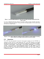
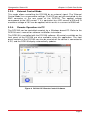
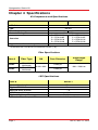
OGK2 and OGK2
Optogenetics Starter Kits
User Guide
Optogenetics Starter Kit
Table of Contents
Chapter 1
Warning Symbol Definitions ........................................... 2
Chapter 2
Safety ................................................................................. 3
Chapter 3
Quick-Start Guide ............................................................. 3
3.1. Setup ............................................................................ 3
3.1.1.
3.1.2.
LED and Driver ......................................................................... 3
Patch Cable and Cannula ......................................................... 3
3.2. Operation ..................................................................... 4
3.2.1.
3.2.2.
3.2.3.
3.2.4.
Constant Current Mode ............................................................. 5
Pulse Width Modulation (PWM) Mode ....................................... 5
External Control Mode .............................................................. 6
Remote Operation via PC ......................................................... 6
Chapter 4
Specifications ................................................................... 7
Chapter 5
Further Reading ................................................................ 8
Chapter 6
Regulatory ......................................................................... 9
6.1. Waste Treatment is Your Own Responsibility ................. 9
6.2. Ecological Background .................................................. 9
Chapter 7
Page 1
Thorlabs Worldwide Contacts....................................... 10
Rev A, June 11, 2012
Optogenetics Starter Kit
Chapter 1: Warning Symbol Definitions
Chapter 1 Warning Symbol Definitions
Below is a list of warning symbols you may encounter in this manual or on your
device.
Symbol
Description
Direct Current
Alternating Current
Both Direct and Alternating Current
Earth Ground Terminal
Protective Conductor Terminal
Frame or Chassis Terminal
Equipotentiality
On (Supply)
Off (Supply)
In Position of a Bi-Stable Push Control
Out Position of a Bi-Stable Push Control
Caution: Risk of Electric Shock
Caution: Hot Surface
Caution: Risk of Danger
Warning: Laser Radiation
Caution: Spinning Blades May Cause Harm
Page 2
Optogenetics Starter Kit
Chapter 2 Safety
SHOCK WARNING
Before applying power to your DC2100 system, make sure that the protective
conductor of the 3-conductor main power cord is correctly connected to the
protective earth contact of the socket outlet!
Improper grounding can cause electric shock with damages to your health or
even death!
WARNING
Optical Power Density out of the output connector or fiber tip may be
hazardous to the human eye – do not look into the connector or fiber
aperture.
See the individual operating manuals for the M470F1 LED and DC2100 LED
Driver for complete warnings and safety information.
Chapter 3 Quick-Start Guide
3.1.
3.1.1.
Setup
LED and Driver
The OGK2 and OGK4 Optogenetics Starter Kits include an M470F1 FiberCoupled LED, and a DC2100 LED Driver. The LED can be operated by
connecting it to the “LED” jack in the back of the DC2100. The power supply for
the DC2100 should be plugged into the unit as well. The DC2100 can then be
powered on using the rocker switch on the back of the unit.
After the device is powered up, the display will show a “Welcome” screen for a
few seconds. The DC2100 is immediately ready for use after turning on.
However, the rated accuracy is reached after a warm-up period of 10 minutes.
3.1.2.
Patch Cable and Cannula
Insert the M51L01 (for OGK2) or M54L01 (for OGK4) patch cable’s SMA
connector into the LED unit by threading the rotating barrel on the connector onto
the LED unit’s housing. Then, place the ADAF1 mating sleeve onto the ferrule
end of the patch cable, leaving approximately one third of the mating sleeve
length exposed for the cannula connection. Then, connect the mating sleeve to
the cannula. Note: To disconnect the cannula, grip the patch cable by the ferrule
and mating sleeve (not the heat shrink tubing) and use a twisting motion.
Page 3
Rev A, June 11, 2012
Optogenetics Starter Kit
Chapter 3: Quick-Start Guide
Figure 1 Insert the Mating Sleeve 1/2 to 2/3 of the way onto the Ferrule End of the
Patch Cable
It is very important that the ends of the patch cable’s ferrule and the cannula’s
ferrule are in physical contact. If they are not, the output power at the cannula tip
will decrease significantly.
Figure 2 The cannula and patch cable must be in physical contact inside the mating
sleeve (left) to avoid light losses at this connection (right).
3.2.
Operation
The LED can be operated using the front panel controls of the DC2100, or
remotely via PC. Use the scroll wheel and “OK” and “ESC” buttons to navigate
through the DC2100’s menus. The DC2100 can operate in three different modes,
‘Constant Current Mode’, ‘PWM Mode’ (Pulse-Width Modulation), or ‘External
Control’. The DC2100 can also be operated remotely via USB. Note: The LED
must be switched off when switching between modes. Use the “ESC” button to
display the main menu, and then use the scroll wheel and “OK” button to select
an operating mode.
Page 4
Optogenetics Starter Kit
Figure 3 Main Menu
3.2.1.
Constant Current Mode
While operating in constant current mode, the scroll wheel controls the LED’s
power (limited to 1 A by the LED unit), and the “LED” button toggles the LED
on/off.
Figure 4 Constant Current Mode
3.2.2.
Pulse Width Modulation (PWM) Mode
In Pulse Width Modulation mode, the frequency, amplitude, duty cycle (pulse
width), and number of pulses can all be defined. The main Pulsed Mode screen
(see figure below) displays each parameter. To edit the parameters, highlight that
line with the scroll when, press “OK”, edit using the scroll wheel, and press “OK”
again to save that parameter. Again, the “LED” button toggles the LED on/off.
With the LED switched off, press “ESC” to return to the main menu.
Figure 5 Pulse Width Modulation Mode
Page 5
Rev A, June 11, 2012
Optogenetics Starter Kit
3.2.3.
Chapter 3: Quick-Start Guide
External Control Mode
This mode allows controlling the DC2100 by an external signal. The 'External
Control Mode' has no parameter settings. The LED can only be controlled via the
BNC connector at the rear panel of the DC2100. The applied voltage
corresponds to the LED current. 1 V is equivalent to a LED current of 200 mA. A
maximum voltage of 10V can be applied, which results in a current of 2000 mA.
3.2.4.
Remote Operation via PC
The DC2100 can be controlled remotely by a Windows-based PC. Refer to the
DC2100 user’s manual for software installation instructions.
The DC2100 is controlled with the DC2100 software. All controls available on the
front panel of the DC2100 are also available using this application. The front
panel controls of the DC2100 can also be used when the device is connected to
a PC, and the DC2100 display automatically updates.
Figure 6 DC2100 PC Remote Control Software
Page 6
Optogenetics Starter Kit
Chapter 4 Specifications
Kit Components and Specifications
Item #
OGK2
LED Driver
LED
Fiber Patch Cable
Cannula Mating Sleeve
OGK4
DC2100
M470F1
M51L01
Cannulae
Approximate Cannula Output Power*
M51L01
5 x ADAF1
5 x CFM12L02
5 x CFM12L02
5 x CFM12L05
5 x CFM12L05
5 x CFM12L10
5 x CFM12L10
5 x CFM12L20
5 x CFM12L20
2.6 mW
2.6 mW
*Tested with the LED driven at maximum current (1 A).
Fiber Specifications
Item #
OGK2
OGK4
Fiber Type
NA
FT200EMT
Multimode
FT400EMT
Multimode
0.39 ± 0.02
Wavelength
Range
Core Diameter
∅200 µm
400 – 2200 nm
∅400 µm
LED Specifications
Item #
M470F1
Center Wavelength
470 nm
Typical FWHM
15 nm
Max CW Drive Current
1A
LED Forward Voltage
3.6 V
Typical Lifetime
>50,000 hours
Refer to the Fiber-Coupled LEDs manual or web presentation for full specifications.
Page 7
Rev A, June 11, 2012
Optogenetics Starter Kit
Chapter 5: Further Reading
LED Driver Specifications
Item #
LED Current Range
LED Current Resolution
LED Current Accuracy
LED Forward Voltage
Modulation Frequency Range
Duty Cycle Range
DC2100
0–2A
1 mA
±20 mA
24 V
0 – 100 kHz, Sine Wave
1 – 100%
Refer to the DC2100 manual or web presentation for full specifications.
Chapter 5 Further Reading
1.
Aravanis A, Wang LP, Zhang F, Meltzer L, Mogri M, Schneider MB,
Deisseroth K. An optical neural interface: in vivo control of rodent
motor cortex with integrated fiberoptic and optogenetic technology. J.
Neural Eng. 2007 Sept; 4:S143-S156.
2.
Gradinaru V, Thompson KR, Zhang F, Mogri M, Kay K, Schneider MB,
Deisseroth K. Targeting and readout strategies for fast optical neural
control in vitro and in vivo. J Neurosci. 2007 Dec 26;27(52):14231-8.
3.
Zhang F, Gradinaru V, Adamantidis AR, Durand R, Airan RD, de Lecea L,
Deisseroth K. Optogenetic interrogation of neural circuits: technology
for probing mammalian brain structures. Nat Protoc. 2010;5(3):439-56.
Epub 2010 Feb 18.
4.
Yizhar O, Fenno LE, Davidson TJ, Mogri M, Deisseroth K. Optogenetics in
Neural Systems. Neuron. 2011 July;72:9-34.
5.
http://www.stanford.edu/group/dlab/optogenetics/
6.
http://www.openoptogenetics.org/index.php?title=Main_Page
Page 8
Optogenetics Starter Kit
Chapter 6 Regulatory
As required by the WEEE (Waste Electrical and Electronic Equipment Directive)
of the European Community and the corresponding national laws, Thorlabs offers
all end users in the EC the possibility to return “end of life” units without incurring
disposal charges.
•
•
•
•
•
•
This offer is valid for Thorlabs electrical and electronic equipment:
Sold after August 13, 2005
Marked correspondingly with the crossed out
“wheelie bin” logo (see right)
Sold to a company or institute within the EC
Currently owned by a company or institute
within the EC
Still complete, not disassembled and not
contaminated
As the WEEE directive applies to self-contained
Wheelie Bin Logo
operational electrical and electronic products, this end of
life take back service does not refer to other Thorlabs products, such as:
•
•
•
•
Pure OEM products, that means assemblies to be built into a unit by the
user (e.g. OEM laser driver cards)
Components
Mechanics and optics
Left over parts of units disassembled by the user (PCB’s, housings etc.).
If you wish to return a Thorlabs unit for waste recovery, please contact Thorlabs
or your nearest dealer for further information.
6.1.
Waste Treatment is Your Own Responsibility
If you do not return an “end of life” unit to Thorlabs, you must hand it to a
company specialized in waste recovery. Do not dispose of the unit in a litter bin
or at a public waste disposal site.
6.2.
Ecological Background
It is well known that WEEE pollutes the environment by releasing toxic products
during decomposition. The aim of the European RoHS directive is to reduce the
content of toxic substances in electronic products in the future.
The intent of the WEEE directive is to enforce the recycling of WEEE. A
controlled recycling of end of life products will thereby avoid negative impacts on
the environment.
Page 9
Rev A, June 11, 2012
Optogenetics Starter Kit
Chapter 7: Thorlabs Worldwide Contacts
Chapter 7 Thorlabs Worldwide Contacts
USA, Canada, and South America
Thorlabs, Inc.
56 Sparta Avenue
Newton, NJ 07860
USA
Tel: 973-300-3000
Fax: 973-300-3600
www.thorlabs.com
www.thorlabs.us (West Coast)
Email: [email protected]
Support: [email protected]
Europe
Thorlabs GmbH
Hans-Böckler-Str. 6
85221 Dachau
Germany
Tel: +49-(0)8131-5956-0
Fax: +49-(0)8131-5956-99
www.thorlabs.de
Email: [email protected]
UK and Ireland
Thorlabs Ltd.
1 Saint Thomas Place, Ely
Cambridgeshire CB7 4EX
Great Britain
Tel: +44 (0)1353-654440
Fax: +44 (0)1353-654444
www.thorlabs.com
France
Thorlabs SAS
109, rue des Côtes
78600 Maisons-Laffitte
France
Tel: +33 (0) 970 444 844
Fax: +33 (0) 825 744 800
www.thorlabs.com
Email: [email protected]
Scandinavia
Thorlabs Sweden AB
Mölndalsvägen 3
412 63 Göteborg
Sweden
Tel: +46-31-733-30-00
Fax: +46-31-703-40-45
www.thorlabs.com
Email: [email protected]
Japan
Thorlabs Japan, Inc.
Higashi-Ikebukuro Q Building 1F
2-23-2, Higashi-Ikebukuro,
Toshima-ku, Tokyo 170-0013
Japan
Tel: +81-3-5979-8889
Fax: +81-3-5979-7285
www.thorlabs.jp
Email: [email protected]
China
Thorlabs China
Room A101, No. 100
Lane 2891, South Qilianshan Road
Putuo District
Shanghai
China
Tel: +86 (0) 21-60561122
Fax: +86 (0)21-32513480
www.thorlabs.hk
Email: [email protected]
Email: [email protected]
Support: [email protected]
Page 10
www.thorlabs.com