1
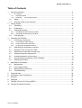
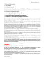
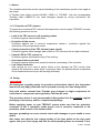
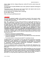
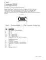
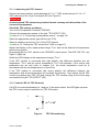
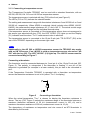
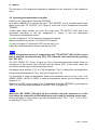
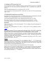
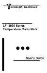
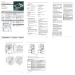
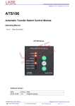
Thermoelectric Temperature Controller TED200C Operation Manual 2011 2 TED200C Version: Date: 3.06 18. Mar. 2011 © 2011 Thorlabs © 2011 Thorlabs General Information 3 Table of Contents 1 General Information................................................................................................................... 5 1.1 1.1.1 1.1.2 2 Safety ................................................................................................................................ 6 1.3 Ordering codes and accessories....................................................................................... 8 Getting started ........................................................................................................................... 8 2.1 Unpacking ......................................................................................................................... 8 2.2 Preparation........................................................................................................................ 8 2.3 Operating Elements........................................................................................................... 9 2.4 Operating elements at the front panel ......................................................................................... 9 Operating elements at the rear panel ........................................................................................ 10 First operation ................................................................................................................. 11 Operating the TED200C .......................................................................................................... 12 3.1 3.1.1 3.1.2 3.1.3 4 General remarks .......................................................................................................................... 5 Protection for the TEC element ............................................................................................. 6 1.2 2.3.1 2.3.2 3 At a Glance........................................................................................................................ 5 Connecting components.................................................................................................. 12 Connecting the TEC element..................................................................................................... 13 Control LED for TEC ON mode.................................................................................................. 13 Connecting a temperature sensor ............................................................................................. 14 3.2 Operating the temperature controller .............................................................................. 16 3.3 Setting the TEC current limit "ILIM"................................................................................. 17 3.4 Adjusting the temperature control loop............................................................................ 17 3.5 Analog tuning of the temperature .................................................................................... 18 3.6 Analog temperature control output .................................................................................. 19 3.7 Over-temperature-protection of the TED200C ................................................................ 19 3.8 Disabling the beeper ....................................................................................................... 19 Maintenance and Repair ......................................................................................................... 20 4.1 Maintenance.................................................................................................................... 20 4.2 Line Voltage Setting ........................................................................................................ 20 4.3 Replacing the mains fuses .............................................................................................. 21 4.4 Troubleshooting............................................................................................................... 22 5 Technical Data......................................................................................................................... 24 6 Certifications and Compliances ............................................................................................... 26 7 Warranty .................................................................................................................................. 27 8 Copyright ................................................................................................................................. 27 9 Thorlabs “End of Life” Policy (WEEE) ..................................................................................... 28 10 Thorlabs Worldwide Contacts.................................................................................................. 29 © 2011 Thorlabs 4 TED200C We aim to develop and produce the best solution for your application in the field of optical measurement technique. To help us to come up to your expectations and develop our products permanently we need your ideas and suggestions. Therefore, please let us know about possible criticism or ideas. We and our international partners are looking forward to hearing from you. Thorlabs WARNING Sections marked with this heading explain dangers that might result in personal injury or death. Always read the associated information carefully before performing the indicated procedure. ATTENTION Paragraphs preceded by this symbol in the manual explain hazards that could damage the instrument and connected equipment or may cause loss of data. NOTE This manual also contains "NOTES" and "HINTS" written in this form. © 2011 Thorlabs General Information 5 1 General Information 1.1 At a Glance 1.1.1 General remarks The thermoelectric Temperature Controller TED200C by Thorlabs is an extremely precise temperature controller for laser diodes and detectors. The TED200C is excellently suited for: wavelength stabilization of laser diodes noise reduction of detectors wavelength tuning by regulating the temperature modulation of wavelength by tuning the temperature The unit is easy to use due to the clearly arranged operating elements on the front panel. The operating parameters are shown by a 5-digit LED display, the measurement value shown is selected via keys. The gain (P-share), the integral share and the derivative share of the PID temperature control loop can be set independent of each other. Different temperature sensors can be used with the temperature controller TED200C, thermistors, or temperature IC sensors: AD590, AD592, LM135, LM 335. With a thermistor the temperature display is shown as resistance value in k, if the TED200C is operated with a temperature sensor IC the temperature is shown in C. The output for the TEC current can be switched on or off via key from the front panel. The temperature sensor and the TEC element are connected by a 15-pin D-sub jack at the rear of the unit. At the output jack a control signal is available to drive an external LED to indicate TEC ON mode when the TEC current loop is activated. The set value of the temperature can be changed with a knob at the front panel or via an analog input at the rear of the unit. An analog voltage proportional to the actual value of the temperature is available at the rear of the unit for monitoring purposes. The unit has been designed for safe operation with environmental temperatures of more than 40 C provided that a free air circulation through the ventilation slots at the rear and at both sides of the unit is maintained. Attention Do not obstruct the air-ventilation slots in the housing! In case of overheating caused by too high environmental temperatures or closed ventilation slots the unit automatically switches the output off to avoid damages. The LED "OTP" (over-temperature-protection) indicates the over-temperature. After temperature drop of about 10 C the LED "OTP" extinguishes and the output current can be switched on again by pressing the key "ON". If an error occurs (OTP or OPEN) the corresponding LED lights up and a beeper gives a short warning signal. © 2011 Thorlabs 6 TED200C The installed mains filter and the careful shielding of the transformer provide a low ripple at the output. If Thorlabs laser diode mounts LM14S2, LDM21 or TCLDM9 with the corresponding Thorlabs cable CAB420-15 are used damages caused by wrong connections are impossible. 1.1.2 Protection of TEC element To protect the connected TEC element the temperature control system TED200C includes the following protective circuits: Limit of the TEC current in all operating modes Protection against thermal destruction. Protection of the sensor Protection against use of incorrect temperature sensors / protection against line interruption of the temperature sensor. Contact protection of the TEC element (open circuit) Protection against cable damage, bad contact or TEC element with too high resistance. Control LED for TEC current on Protection against accidental turning off the cooling. Over-temperature protection Protection against malfunction caused by internal overheating of the controller. Line failure protection After turning on or in case of power failure or line damage the TEC current must explicitly be switched on anew since it cannot be taken for granted that all components of the measurement set-up are still working faultlessly. 1.2 Safety Attention All statements regarding safety of operation and technical data in this instruction manual will only apply when the unit is operated correctly as it was designed for. Only with written consent from Thorlabs may changes to single components be carried out or components not supplied by Thorlabs be used. This precision device is only transportable if duly packed into the complete original packaging. If necessary, ask for a replacement package. Before applying power to your TED200C system make sure that the protective conductor of the 3 conductor mains power cord is correctly connected to the protective earth contact of the socket outlet! Improper grounding can cause electric shock with damages to your health or even death! Also make sure that the line voltage setting of the fuse holder at the rear panel agrees with your local supply and that the corresponding fuses are inserted. If not, © 2011 Thorlabs General Information 7 please change the line voltage setting (see section 4.2) and the mains fuses (see section 4.3). The temperature controller TED200C must not be operated in explosion endangered environments! Temperature sensor, TEC element and control inputs and outputs must only be connected with duly shielded connection cables. Do not obstruct the air ventilation slots in housing! Do not remove covers! Refer servicing to qualified personnel! Attention The following statement applies to the products covered in this manual, unless otherwise specified herein. The statement for other products will appear in the accompanying documentation. Note: This equipment has been tested and found to comply with the limits for a Class B digital device, pursuant to Part 15 of the FCC Rules and meets all requirements of the Canadian Interference-Causing Equipment Standard ICES-003 for digital apparatus. These limits are designed to provide reasonable protection against harmful interference in a residential installation. This equipment generates, uses, and can radiate radio frequency energy and, if not installed and used in accordance with the instructions, may cause harmful interference to radio communications. However, there is no guarantee that interference will not occur in a particular installation. If this equipment does cause harmful interference to radio or television reception, which can be determined by turning the equipment off and on, the user is encouraged to try to correct the interference by one or more of the following measures: Reorient or relocate the receiving antenna. Increase the separation between the equipment and receiver. Connect the equipment into an outlet on a circuit different from that to which the receiver is connected. Consult the dealer or an experienced radio/T.V. technician for help. Thorlabs GmbH is not responsible for any radio television interference caused by modifications of this equipment or the substitution or attachment of connecting cables and equipment other than those specified by Thorlabs GmbH. The correction of interference caused by such unauthorized modification, substitution or attachment will be the responsibility of the user. The use of shielded I/O cables is required when connecting this equipment to any and all optional peripheral or host devices. Failure to do so may violate FCC and ICES rules. Mobile telephones, cellular phones or other radio transmitters are not to be used within the range of three meters of this unit since the electromagnetic field intensity may then exceed the maximum allowed disturbance values according to IEC61326-1. This product has been tested and found to comply with the limits according to IEC61326-1 for using connection cables shorter than 3 meters (9.8 feet). © 2011 Thorlabs 8 TED200C 1.3 Ordering codes and accessories Ordering code Short description TED200C thermoelectric Temperature Controller, TEC current 0 ... 2 A, working with thermistors and temperature IC sensors (AD 590, AD 592, LM135 and LM 335) as temperature sensor, 5-digit LED-display Shielded cable: CAB420-15 Cable to connect the temperature controller TED200C to a Thorlabs Laser Diode Mount. Please visit our homepage http://www.thorlabs.com for further information. 2 Getting started 2.1 Unpacking Inspect the shipping container for damage. If the shipping container seems to be damaged, keep it until you have inspected the contents and you have inspected the TED200C mechanically and electrically. Verify that you have received the following items: 1. 1 TED200C 2. 1 power cord, connector according to ordering country 3. 1 operation manual 4. 1 connection cable CAB420-15 2.2 Preparation Prior to starting operation with a temperature controller TED200C, check if the line voltage set with the voltage selector at the rear panel agrees with your local supply and if the appropriate fuses are inserted. (See chapter 4.2 on page 20 to change the line voltage and chapter 4.3 on page 21 to exchange the mains fuses.) Connect the unit to the line with the provided mains cable. Turn the unit on by means of the line switch (F11). Via the connector jack of the chassis ground (R4) the external optical build-up can be connected to ground potential, if required. © 2011 Thorlabs Getting started 9 2.3 Operating Elements 2.3.1 Operating elements at the front panel F1 F11 F12 Figure 1 F1 F2 F3 F4 F5 F6 F7 F8 F9 F10 F11 F12 F13 F14 F15 F16 F17 F18 F19 F20 F21 F22 F23 F24 F25 F2 F3 F4 F5 F6 F7 F8 F9 F10 F13 F14 F15 F16 F17F18F19F20 F21F22 F23F24 F25 Display and operating elements at the front panel 5-digit LED display LED "°C" Temperature display in C LED "kΩ" Resistance display in k LED "OPEN" Current display in A LED "OTP" Over temperature protection is active LED "OPEN" TEC element is not connected or too high resistance LED "NO SENSOR" Temperature sensor is wrong or not connected LED "TEC ON" TEC output is switched on Key "TEC ON" On / Off switch for the TEC output Knob for adjusting the set temperature / resistance Line switch (ON / OFF) LIM I Potentiometer for setting the TEC current limit Display shows the actual temperature / resistance LED "TACT" LED "ITEC" Display shows the TEC current Display shows the set temperature / resistance LED "TSET" LED "ILIM" Display shows the current limit Key “DOWN” Select the parameter to be displayed Key “UP” Select the parameter to be displayed LED "AD590" Selected sensor is AD 590, AD 592, LM 135 or LM 335 LED "TH 200kΩ" Selected sensor is thermistor in the 200 kΩ range LED " TH 20kΩ " Selected sensor is thermistor in the 20 kΩ range P Potentiometer for setting P- (gain) share of control loop I Potentiometer for setting I- (integral) share of control loop D Potentiometer for setting D- (derivative) share of control loop Key “SENSOR” Select sensor / disable I-share (press for more than 1 sec.) © 2011 Thorlabs 10 TED200C 2.3.2 Operating elements at the rear panel R1 R2 R3 R4 R8 R5 R6 Figure 2 R1 R2 R3 R4 R5 R6 R7 R8 R7 Operating elements at the rear panel Analog temperature control input "TUNE IN", -10 ... +10 V Analog temperature control output "CTL OUT", -10 … +10 V Fan 4 mm banana jack for chassis ground 15-pin D-sub jack for the TEC element and the temperature sensor “TE OUTPUT” Serial number of the unit Indicator / switch for line voltage (included in fuse holder) Mains connector and fuse holder © 2011 Thorlabs Getting started 11 2.4 First operation Attention Prior to switching on your TED200C please check if the line voltage set with the voltage selector at the rear panel corresponds to your mains voltage! If the selected voltage is not appropriate, refer to 4.2, “Line Voltage Setting” Turn on the unit by means of the line switch (F11). After switching on the unit, the LED display (F1) must get visible and a LED must light up to indicate the selected measurement value (F13 … F16). If no display is shown, please check the line voltage (see chapter 4.2 on page 20) and the mains fuses (see chapter 4.3 on page 21). By using the keys (F17) and (F18) you can select the desired measurement value to be displayed at any time. The unit TED200C is immediately ready to use after turning on. The rated accuracy is reached, however, after a warming-up time of approx. 10 minutes. © 2011 Thorlabs 12 TED200C 3 Operating the TED200C 3.1 Connecting components Connecting TEC element and temperature sensor If Laser Diode Mounts by Thorlabs are used, just connect the 15-pin D-Sub jack "TE OUTPUT" (R5) of the Temperature Controller TED200C to the 9-pin plug "TEC DRIVER" of the Laser Diode Mount with a shielded cable CAB420-15. With other equipment connect the TEC element and the temperature sensor according to Figure 3. 8 7 6 5 4 3 2 1 15 14 13 12 11 10 9 Figure 3 Pin assignment of the “TE OUTPUT” jack (female, rear panel view) Pin Connection 5 6 7 13 14 15 1 TEC element, status indication: TEC (+) TEC (+) TEC (+) TEC (-), status-LED (-) TEC (-), status-LED (-) TEC (-), status-LED (-) Status-LED (+) (for TEC ON/OFF indication) 4 3 10 11 2 9 12 8 Temperature sensor: Thermistor (+) Thermistor (-), ground Transducer AD 590/592 (-), LM 135/335 (+) Transducer AD 590/592 (+), LM135/335 (+) N.C. N.C. N.C. AGND LM 135/335 (-) © 2011 Thorlabs Operating the TED200C 13 3.1.1 Connecting the TEC element Connect the thermoelectric cooler between pin 5, 6, 7 (TEC anode) and pin 13, 14, 15 (TEC cathode) of the 15-pin D-sub jack (R5, see Figure 2). Attention A reverse poled TEC element may lead to thermal runaway and destruction of the connected components. Check the TEC polarity as follows: Turn on the Temperature Controller TED200C Connect the temperature sensor to the jack "TE OUTPUT" (R5) (refer to 3.1.3, "Connecting a temperature sensor " on page 14). Select the appropriate sensor type with the key (F25). Select a suitable current limit "ILIM" for the TEC element (refer to 3.3, “Setting the TEC current limit "ILIM" on page 17). Switch the Display to the measurement range "TSET" and set the desired set temperature with the tuning knob. By pressing the key "ON" switch on the TED200C output current. The LED "ON" (F8 , see Figure 1) lights up. Switch the LED display to the measurement range "TACT". If the TEC module is connected with right polarity, the difference between the set temperature "TSET" and the actual temperature "TACT" will decrease. If the control loop parameters are set well (refer to chapter 3.4), the actual temperature must be in accordance with the set temperature in a short time. If the TEC module is connected with wrong polarity, the difference between set temperature and actual temperature will increase continuously. Then switch off the TEC current by pressing key "ON" (F9) and change the TEC module wiring at the D-sub plug connected to the jack “TE OUTPUT” (R5). 3.1.2 Control LED for TEC ON mode If a LED is connected between pin 1 and pin 15 as shown below, this LED lights up when the TEC current output is switched on (TEC ON mode). 1 15 Figure 4 © 2011 Thorlabs TEC ON monitoring 14 TED200C 3.1.3 Connecting a temperature sensor The Temperature Controller TED200C can be used with a standard thermistor, with an AD 590, AD 592, LM 135 or an LM 335 as temperature sensor. The temperature sensor is selected with key (F25) at the front (see Figure 2). The LED’s (F19 to F21) indicate the selected sensor. The setting and measurement range with thermistors is between 0 and 20.000 k or 0 and 200.00 k, respectively. When AD590 is selected (which includes also AD592, LM135, LM335), the measurement range is between -45 C and +145 C. The actual control range depends on the sensor ratings and the individual thermal setup. If no temperature sensor is connected or if the temperature sensor does not correspond to the sensor type selected with key (F25), the LED “OPEN” (F6) lights up and the Display (F1) indicates overflow when "TACT" measurement value is selected. The temperature sensor is connected to the 15-pin D-sub jack "TE OUTPUT" (R5) at the rear of the TED200C depending on the sensor type used. NOTE Additionally to the AD 590 or AD592 temperature sensor the TED200C also works with an LM 335 sensor. If an LM 335 is used as temperature sensor also select "AD 590" with the key (25). The LED "AD 590" (19) lights up. The LM 335 sensor must be connected according to Figure 7. Connecting a thermistor The thermistor must be connected between pin 3 and pin 4 of the 15-pin D-sub jack (R5, Figure 2). The polarity is unimportant if the thermistor is floating. If one pin of the thermistor is grounded (for example in a laser module), this pin has to be connected to pin3. If the Temperature Controller TED200C is operated with a thermistor as temperature sensor the thermistor resistance is set in k (select "TSET" for display). Figure 5 Connecting a thermistor When the actual temperature "TACT" is chosen for display the thermistor resistance is shown. The key (F25, Figure 2) selects the resistance range of the thermistor between a maximum thermistor resistance of 20 k (measurement current is 100 A) and a maximum thermistor resistance of 200 k (measurement current is 10 A). The dependency of resistance on temperature and vice versa of an NTC-thermistor is described by the formula: © 2011 Thorlabs Operating the TED200C 15 R(T ) R 0 e 1 1 Bval ( ) T T0 T ( R) Bval * T0 R T0 * ln( ) Bval R0 with: R0: Thermistor nominal resistance at temperature T0 T0: Nominal temperature (typ. 298.15 K = 25°C) Bval: Energy constant (temperatures in Kelvin) For R0 and Bval refer to the data sheet of the thermistor. Evaluate the thermistor resistance for the desired set temperature. If the thermistor characteristic R(T) is given in the data sheet the thermistor resistance can be read directly. Select the display value "TSET" with the key (F18, Figure 1) or (F19) to show the resistance set value. Adjust the value with the tuning knob (F10). Temperature sensor AD 590 or AD 592 If the temperature/current transducer AD 590 or AD 592 is used as temperature sensor it is connected between pin 10 (-) and pin 11 (+) of the 15-pin D-sub jack "TE OUTPUT" (R5, Figure 2) at the rear of the unit. The accuracy of the displayed temperature depends on the tolerance of the transducer used. 10 11 Figure 6 Connecting a temperature sensor AD 590 or AD 592 Temperature sensor LM 135 or LM335 If the temperature/voltage transducer LM135 or LM335 is used as temperature sensor it is connected to pin 10 (+), pin 11 (also +) and pin 8 (AGND) of the 15-pin D-sub jack "TE OUTPUT" (R5, Figure 2) at the rear of the unit. 10 11 8 Figure 7 © 2011 Thorlabs Connecting a temperature sensor LM 135 or LM 335 16 TED200C The accuracy of the displayed temperature depends on the tolerance of the transducer used. 3.2 Operating the temperature controller Switch on the Temperature Controller TED200C Use cable CAB420-15 to connect the input "TEC DRIVER" of the Thorlabs Laser Diode Mount to the jack "TE OUTPUT" (R5, Figure 2) at the rear of the Temperature Controller TED200C. If other laser diode sockets are used, the output jack “TE OUTPUT” (R5) has to be connected according to the pin assignment in Figure 3 and the description ”Connecting a temperature sensor” (refer to chapter 3.1.3 Connecting a temperature sensor). Select a suitable current limit "ILIM" for the TEC element (refer to chapter 3.3 Setting the TEC current limit "ILIM"). Select the used temperature sensor with the key (F25). NOTE Only if a temperature sensor is connected to jack "TE OUTPUT" (R5) and the sensor type is selected correctly with key (F25), TEC ON mode can be selected by pressing key "ON" (R1). The LED "OPEN" (F6, Figure 1) lights up if the connected temperature sensor does not correspond to the sensor type selected with the switch (R6). In this case check the connection and the type of the temperature sensor. Set display value with key (F17) or (F18) into position "TSET" to display the set temperature. Set the desired temperature "TSET" with the tuning knob (F10). If a thermistor is used as temperature sensor the resistance has to be set in k. If an AD590, AD592, LM135 or LM335 is used as temperature sensor the set temperature is entered in °C. Switch on the TEC current output of the Temperature Controller TED200C by pressing key "ON" (F9). With the output switched on the LED "ON" (F8) lights up. NOTE When the LED "OPEN" (F6) lights up the controller cannot be switched on. In this case check the connection of the temperature sensor and the selected sensor type. During operation you can chose at any time the display value "TSET", "TACT", "ILIM" or "ITEC" by pressing (F17) or (F18). © 2011 Thorlabs Operating the TED200C 17 3.3 Setting the TEC current limit "ILIM" The Temperature Controller TED200C delivers a maximum TEC current of 2 A. The TEC current limit "ILIM" can be set with the potentiometer "LIM I" according to the used TEC element. Select the display parameter "ILIM" with the key (F17) or (F18). Use a screwdriver to set the desired TEC current limit "ILIM" with the 12-turn potentiometer "LIM I" (F12). 3.4 Adjusting the temperature control loop By setting the control loop parameters of the PID control loop the temperature controller TED200C can be adapted optimal to the most different thermal loads. The P-share (proportional, gain) can be adjusted with potentiometer "P" (F22). The I-share (integral, offset control) can be adjusted with potentiometer "I" (F23). The D-share (derivative, rate control) can be adjusted with potentiometer "D" (F24). Execution: Switch with key (F17) or (F18) into the position "TACT" to display the actual temperature or thermistor resistance. Turn the three potentiometers "P" (F22), "I" (F23) and "D" (F24) completely counterclockwise. NOTE The settling behavior may be additionally observed at the "CTL OUT" output (R2, Figure 2) at the rear of the unit by means of an oscilloscope or chart recorder. Switch off the I-share to make the setting of the gain (P-share) and the D-share easier. Press key (F25) for at least one second to switch off the I-share. The sensor indicator LED is flashing to indicate the I-share off state. Set the temperature "TSET" to about room temperature and switch on the TEC current output with the switch " ON" (F9). P-Share Repeatedly increase and decrease the set temperature about 1 …2 C around room temperature with knob (F10, see Figure 1) or by applying a suited slow square wave signal to the analog control input "TUNE IN" (R1, see Figure 2) at the rear of the unit. Watch the settling behavior of the actual temperature "TACT". Increase the P-share gradually by turning potentiometer (F22) clockwise. Higher values will increase the settling speed. Too high values will increase the amplitude and number of overshoots or will even make the system instable (continuous oscillation). The P-share has been set correctly when the actual temperature remains stable near the set temperature after only 2 … 3 overshoots. © 2011 Thorlabs 18 TED200C D-share Change again repeatedly between set temperatures ± (1...2)°C around room temperature while observing the settling behavior of the actual temperature. Increase the D-share gradually by turning potentiometer (F23) clockwise. Higher values will decrease the amplitude and number of overshoots. Too high values will increase again the amplitude and number of overshoots or will even make the system instable. The D-share is set correctly when the actual temperature remains stable at a value near the set temperature after a minimum of overshoots. I-share Turn on the I-share again (if disabled) by pressing key (F25) for at least one second. The sensor indicating LED stops flashing when the I-share is enabled. Change again repeatedly between set temperatures ± (1...2)°C around room temperature. Increase the I-share gradually by turning potentiometer (F24) clockwise. Higher values will accelerate the settling to the set temperature. Too high values will increase the amplitude and number of overshoots. The I-share is set correctly when the actual temperature reaches the set temperature in short time with at most one overshoot. 3.5 Analog tuning of the temperature The set temperature "TSET" can be tuned by an analog voltage via an independent grounded input "TUNE IN" (R1, Figure 2) at the rear panel of the Temperature Controller TED200C. The temperature set value is proportional to the sum of the signal at the input "TUNE IN" (R1) and the value set with the adjust knob (F10, Figure 1). The tuning range for the analog control input "TUNE IN" (R1) is: range voltage operation mode 0 ... 20 k 0 ... 10 V thermistor, TH 20kΩ range 0 ... 200 k 0 ... 10 V thermistor, TH 200kΩ range -45 °C...+145 °C - 2.25 V...+7.25 V AD 590/592, LM 135/335 Execution: Connect the temperature sensor and the TEC element to jack "TE OUTPUT" (R5) and switch on the Temperature Controller TED200C. Select an adequate TEC current limit "ILIM". Select the sensor type with key (F25) and set the desired set temperature "TSET" with the tuning knob. Switch on the TEC current output of the Temperature Controller TED200C by pressing key "ON" (F9). TEC ON mode is indicated by LED (F8) next to the key "ON". Apply an analog voltage to jack "TUNE IN" (R1) at the rear panel of the Temperature Controller TED200C. © 2011 Thorlabs Operating the TED200C 19 NOTE Only slow variations of the temperature set value (<< 1 Hz) are possible via the analog control input "TUNE IN" (R1). At the analog temperature control output "CTL OUT" (R2) the actual temperature "TACT" can be supervised. 3.6 Analog temperature control output An analog output "CTL OUT" (R2, see Figure 2) is provided at the rear of the Temperature Controller TED200C. Here a voltage proportional to the actual temperature "TACT" is applied for monitoring purposes e.g. to supervise the settling behavior of the temperature control loop. range voltage operation mode 0 ... 20 k 0 ... 10 V thermistor, TH 20kΩ range 0 ... 200 k 0 ... 10 V thermistor, TH 200kΩ range -45 °C...+145 °C - 2.25 V...+7.25 V AD 590/592, LM 135/335 E.g. a strip chart recorder may be connected to this output to see if certain temperature limits of the device under test are exceeded. The output "CTL OUT" (R2) is grounded. Thus standard measurement equipment can be connected directly. Devices connected to these outputs should have an input resistance of 10 k. 3.7 Over-temperature-protection of the TED200C The temperature controller TED200C has an automatic over-temperature protection. If the unit is internally overheated by operating errors or high ambient temperatures the current output is switched off automatically. LED "OTP" (F5, see Figure 1, “Over Temperature protection”), lights up and the beeper gives a short warning signal. The current through the TEC element is switched off (TEC OFF mode). Pressing key "ON" (F9) has no effect in this case. When the temperature within the unit has dropped for about 10 °C the LED "OTP" (F5) extinguishes and the TEC current output can be switched on again. 3.8 Disabling the beeper If audible signals are unwanted, the beeper can be disabled in this way: Press the key “Up” (F18). While holding it, press the key “Down” (F17). Now the beeper state is displayed: “Sd.On” “Sd.OFF” Sound ON Sound OFF Repeating to press the key “Down” while still holding the key “Up” toggles the beeper state. © 2011 Thorlabs 20 TED200C 4 Maintenance and Repair 4.1 Maintenance Protect the TED200C from adverse weather conditions. The TED200C is not water resistant. Attention To avoid damage to the TED200C, do not expose it to spray, liquids or solvents! The unit does not need a regular maintenance by th user. If necessary the unit and the display can be cleaned with a cloth dampened with water. You can use a mild 75% Isopropyl Alcohol solution for more efficient cleaning. The TED200C does not contain any modules that could be repaired by the user himself. If a malfunction occurs, the whole unit has to be sent back to Thorlabs. Do not remove covers! To guarantee the specifications given in chapter Technical Data over a long period it is recommended to have the unit calibrated by Thorlabs every two years. 4.2 Line Voltage Setting The temperature controller TED200C operates at fixed line voltages of: 100 V +15% -10% (90 V … 115 V), 115 V +15% -10% (104 V … 132 V) or 230 V +15% -10% (207 V … 264 V), line frequency 50 … 60 Hz. The line voltage setting can be changed from the rear without opening the unit. 1. Turn off the TED200C and disconnect the mains cable. 2. The fuse holder (R9, see Figure 8) is located below the 3-pole power connector of the mains jack (R8). Release the fuse holder by pressing its plastic retainers with the aid of a small screwdriver. The retainers are located on the right and left side of the holder and must be pressed towards the center. 3. Unplug the white line voltage switch / indicator (R7, containing the left fuse) from the fuse holder (R9), rotate it until the appropriate voltage marking (100V, 115V, or 230V) is on target for the cutout (R11) of the fuse holder, and plug it back into the fuse holder. Press in the fuse holder until locked on both sides. The appropriate line voltage marking must be visible in the cutout (R11) of the fuse holder. Attention If you have changed to or from 230 V, change the mains fuse to the value shown in section 4.3 of this manual! © 2011 Thorlabs Maintenance and Repair 21 4.3 Replacing the mains fuses The two power input fuses are externally accessible. If they have opened due to line distortions, incorrect line voltage or other causes, they can be replaced from the rear without opening the unit. Attention To avoid risk of fire only the appropriate fuses for the corresponding line voltage must be used. 1. Turn off the TED200C and disconnect the mains cable. 2. The fuse holder (R9, see Figure 8) is located below the 3-pole power connector of the mains jack (R8). Release the fuse holder by pressing its plastic retainers with the aid of a small screwdriver. The retainers are located on the right and left side of the holder and must be pressed towards the center. 3. Replace the defective fuses (R10) and press in the fuse holder until locked on both sides. Take care to maintain the correct rotation of the white line voltage indicator / switch (R7) which contains the left fuse and is plugged into the fuse holder. The appropriate line voltage marking must be visible in the cutout (R11) of the fuse holder. Fuse types 100 V 500 mA, time-lag, 250V T0.5A250V 115 V 500 mA, time-lag, 250V T0.5A250V 230 V 250 mA, time-lag, 250V T0.25A250V All fuses must meet IEC specification 60127-2/III, time characteristic: time-lag (T), 250V AC, size 5 x 20 mm. R8 R7 R10 R9 R11 Figure 8 © 2011 Thorlabs Setting the line voltage or changing the mains fuses 22 TED200C 4.4 Troubleshooting In case that your TED200C shows malfunction please check the following items: Unit does not work at all (no display at the front): TED200C connected properly to the mains? Check the mains cable and the line voltage setting (please refer to section 4.2 on page 20) TED200C turned on? Turn on your TED200C with the key mains-switch. Check the fuses at the rear panel (see chapter 4.3 on page 21). If blown replace the fuses by the correct type. (refer to chapter 4.3 on page 21 to select the appropriate fuse type) The display works but you don’t get the desired operation temperature Is the hardware current limit ILIM set to 0? Adjust the hardware limit ILIM by means of the potentiometer "LIM I" (F12) on the TED200C front panel to an appropriate value. Is the TEC connected properly to the D-SUB connector? Check all cables. Check the correct polarity (see chapter 3.1.1 Connecting the TEC element on page 13) Is the temperature sensor connected properly and is the sensor type selected correctly? Check the corresponding connections and polarities of the temperature sensor. (refer to chapter 3.1.3 Connecting a temperature sensor on page 14) Select the corresponding temperature sensor by pressing key (F25, Figure 2). Adjust the right set value for TSET After pressing “TEC ON” the unit beeps and the error LED “OPEN” lights up Is the TEC connected properly to the D-SUB connector? Check all cables. (see chapter 3.1.1 Connecting the TEC element on page 13) The operation temperature is oscillating Are the control loop parameters of the PID control loop adjusted correctly ? Set the P share, D share and I share appropriate to the thermal load (see chapter 3.4 Adjusting the temperature control loop on page 17) © 2011 Thorlabs Maintenance and Repair 23 The unit switches on, but display shows error message (e.g., “Err06”) This indicates a malfunction of the TED200C. In such case, the controller needs to be returned to Thorlabs for maintenance. Please contact a Thorlabs office (see chapter 10 Thorlabs Worldwide Contacts on p. 29) with the information of the error code number and the serial number of your TED200C in order to receive the RMA (Return Material Authorization) instructions accordingly. If you don’t find the error source by means of the trouble shooting list please contact Thorlabs for advise and/or return instructions. © 2011 Thorlabs 24 TED200C 5 Technical Data (All technical data are valid at 23 ± 5°C and 45 ±15% humidity) Temperature sensor: Type of sensor Thermistor, AD590, AD592, LM135, LM335 100 A / 10 A Thermistor sensing current (TH 20k / 200k) Control range (AD590, LM135) -45 C ... +145 C Control range (AD592) -25 C ... +105 C Control range (LM 335) -40 C ... +100 C Control range (Thermistor 20k / 200k) 10 ... 20.000 k / 100 ... 200.00 k Resolution (AD590, AD592, LM135, LM 335) Resolution (Thermistor 20k / 200k) Accuracy (AD590, AD592, LM135, LM 335) Accuracy (Thermistor 20k / 200k) 0.01 C 1 / 10 0.1 C 10 / 100 Temperature stability 24 hours (AD590, AD592, LM135, LM 335) < 0.002 C Temperature stability 24 hours (Thermistor 20k / 200k) 1) < 0.5 / 5 TEC output: Control range of the TEC current Measurement resolution TEC current Measurement accuracy TEC current - 2 A ... + 2 A 1 mA ± 10 mA Max. output voltage >6V Max. output power 12 W Noise and ripple (typ.) < 1 mA TEC current limit: Setting range Resolution Setting accuracy 1) 0 ... 2 A 1 mA 20 mA Due to the nonlinear conversion from Ω to °C the stability in °C depends on the operating conditions and the characteristics of the thermistor. E.g. for a typical thermistor at a set point of 10kΩ (25°C), a 0.5Ω stability translates into about 1mK temperature stability. At a set point of 5kΩ (38°C), the stability is about 2mK. © 2011 Thorlabs Technical Data 25 Temperature control input (TUNE IN): Input resistance 10 k Control voltage -10 ... +10 V Transmission coefficient (AD590, AD592, LM135, LM 335) Transmission coefficient (Thermistor 20k / 200k) 20 C/V ± 5% 2 k/V, 20 k/V ± 5% Temperature control output (CTL OUT): Minimum load resistance 10 k Output voltage (AD590, AD592, LM135, LM 335) -10 … +10 V Output voltage (Thermistor 20k / 200k) 0 … +10 V / 0 … +10 V Transmission Coefficient (AD590, AD592, LM135, LM 335) Transmission Coefficient (Thermistor 20k / 200k) 50 mV/C ± 5% 0.5 V/k / 50 mV/k ± 5% Connectors: Temperature sensor, TEC element, TEC ON signal 15-pin D-sub jack (female) Control input, TUNE IN BNC Control output, CTL OUT BNC Chassis ground 4 mm banana jack Mains input IEC 60320 General data: Line voltage (selectable) 100 V / 115 V / 230 V (-10%, +15 %) Line frequency 50 ... 60 Hz Power consumption (max.): 60 VA Supply mains over voltage Category II (Cat II) Operating temperature 1) 0 ... +40C Storage temperature Relative Humidity -40C ... +70C Max. 80% up to 31 °C, decreasing to 50% at 40 °C Pollution Degree (indoor use only) Operation altitude 2 < 2000 m Warm-up time for maximum accuracy <10 min Weight < 3.1 kg Dimensions (W x H x D) without operating elements 146 x 66 x 290 mm³ Dimensions (W x H x D) with operating elements 146 x 77 x 320 mm³ 1) non condensing © 2011 Thorlabs 26 TED200C 6 Certifications and Compliances Certifications and compliances Category Standards or description EC Declaration of Conformity EMC Meets intent of Directive 89/336/EEC for Electromagnetic Compatibility. Compliance was demonstrated to the following specifications as listed in the Official Journal of the European Communities: EN 61326:1997 Electrical equipment for measurement, control and laboratory use – EMC requirements: +A1:1998 +A2:2001 Immunity: complies with immunity test requirements for +A3:2003 equipment intended for use in industrial locations 1,2. Emission: complies with EN 55011 Class B Limits 1,2,3, IEC 61000-3-2 and IEC 61000-3-3. IEC 61000-4-2 Electrostatic Discharge Immunity (Performance criterion A) IEC 61000-4-3 Radiated RF Electromagnetic Field Immunity (Performance Criterion A) 5 IEC 61000-4-4 Electrical Fast Transient / Burst Immunity (Perf. Criterion A) IEC 61000-4-5 Power Line Surge Immunity (Performance Criterion A) IEC 61000-4-6 Conducted RF Immunity (Performance Criterion A) IEC 61000-4-8 Power Frequency Magnetic Field Immunity (Perf. Criterion A) IEC 61000-4-11 Voltage Dips, Short Interruptions and Voltage Variations Immunity (Performance Criterion A / B 6) IEC 61000-3-2 AC Power Line Harmonic Emissions IEC 61000-3-3 Voltage Fluctuations and Flicker FCC EMC Emissions comply with the Class B Limits of FCC Code of Federal Regulations 47, Compliance Part 15, Subpart B 1,2,3. EC Declaration Compliance was demonstrated to the following specification as listed in the Official of Conformity Journal of the European Communities: Low Voltage Low Voltage Directive 73/23/EEC, amended by 93/68/EEC EN 61010-1:2001 Safety requirements for electrical equipment for measurement, control and laboratory use. U.S. Nationally UL 61010-1 2nd ed. Safety requirements for electrical Recognized equipment for measurement, control, and Testing laboratory use. Laboratory ISA-82:02.01 Safety requirements for electrical Listing equipment for measurement, control, and laboratory use. Canadian CAN/CSA C22.2 No. 61010-1-04 Safety requirements for electrical Certification equipment for measurement, control, and laboratory use. Additional IEC 61010-1:2001 Safety requirements for electrical Compliance equipment for measurement, control, and laboratory use. Equipment Type Test and measuring Safety Class Class I equipment (as defined in IEC 60950-1:2001) 1 Compliance demonstrated using high-quality shielded interface cables shorter than 3 meters. 2 Compliance demonstrated with CAB420-15 cable installed at the TE OUTPUT port with TCLDM9 Laser Diode Mount attached at other end. 3 Emissions, which exceed the levels required by these standards, may occur when this equipment is connected to a test object. 5 TUNE IN port capped at IEC 61000-4-3 test. 6 Performance Criterion B was reached at additional test levels according to EN 61326-1:2006 table 2 © 2011 Thorlabs Warranty 27 7 Warranty Thorlabs warrants material and production of the TED200C for a period of 24 months starting with the date of shipment. During this warranty period Thorlabs will see to defaults by repair or by exchange if these are still entitled to warranty. For warranty repairs or service the unit must be sent back to Thorlabs Germany or to a place determined by Thorlabs. The customer will carry the shipping costs back to Thorlabs, in case of warranty repairs Thorlabs will carry the shipping costs back to the customer. If no warranty repair is applicable the customer will also carry the costs for back shipment. If the unit is sent back to Thorlabs from abroad the customer will carry all shipping costs, duties etc. which should arise for sending the goods back to Thorlabs. Thorlabs warrants the hardware and software determined by Thorlabs for this unit to operate without fault provided that they are handled according to our statements. However, Thorlabs does not warrant a fault free or uninterrupted operation of the unit, of the software or firmware for special applications nor this operation manual to be fault free. We will not carry responsibility for ensuing damages. Restriction of warranty The aforementioned warranty does not cover errors and defects being the result of improper treatment, software and interface not supplied by us, modification, misuse or operation outside the defined ambient conditions stated by us or unauthorized maintenance. Further claims will not be consented to and will not be acknowledged. Thorlabs does explicitly not warrant the usability or the economical use for certain cases of application. Thorlabs reserves the right to change this operation manual or the technical data of the described unit at any time. 8 Copyright Thorlabs GmbH has taken every possible care in preparing this Operation Manual. We however assume no liability for the content, completeness or quality of the information contained therein. The content of this manual is regularly updated and adapted to reflect the current status of the software. We furthermore do not guarantee that this product will function without errors, even if the stated specifications are adhered to. Under no circumstances can we guarantee that a particular objective can be achieved with the purchase of this product. Insofar as permitted under statutory regulations, we assume no liability for direct damage, indirect damage or damages suffered by third parties resulting from the purchase of this product. In no event shall any liability exceed the purchase price of the product. Please note that the content of this User Manual is neither part of any previous or existing agreement, promise, representation or legal relationship, nor an alteration or amendment thereof. All obligations of Thorlabs GmbH result from the respective contract of sale, which also includes the complete and exclusively applicable warranty regulations. These contractual warranty regulations are neither extended nor limited by the information contained in this User Manual. Should you require further information on this product, or encounter specific problems that are not discussed in sufficient detail in the User Manual, please contact your local Thorlabs dealer or system installer. All rights reserved. This manual may not be reproduced, transmitted or translated to another language, either as a whole or in parts, without the prior written permission of Thorlabs GmbH. Status: 2010 © Thorlabs GmbH. All rights reserved. © 2011 Thorlabs 28 TED200C 9 Thorlabs “End of Life” Policy (WEEE) As required by the WEEE (Waste Electrical and Electronic Equipment Directive) of the European Community and the corresponding national laws, Thorlabs offers all end users in the EC the possibility to return “end of life” units without incurring disposal charges. This offer is valid for Thorlabs electrical and electronic equipment th sold after August 13 2005 marked correspondingly with the crossed out “wheelie bin” logo (see below) sold to a company or institute within the EC currently owned by a company or institute within the EC still complete, not disassembled and not contaminated As the WEEE directive applies to self contained operational electrical and electronic products, this “end of life” take back service does not refer to other Thorlabs products, such as pure OEM products, that means assemblies to be built into a unit by the user (e. g. OEM laser driver cards) components mechanics and optics left over parts of units disassembled by the user (PCB’s, housings etc.). If you wish to return a Thorlabs unit for waste recovery, please contact Thorlabs or your nearest dealer for further information. Waste treatment on your own responsibility If you do not return an “end of life” unit to Thorlabs, you must hand it to a company specialized in waste recovery. Do not dispose of the unit in a litter bin or at a public waste disposal site. Ecological background It is well known that WEEE pollutes the environment by releasing toxic products during decomposition. The aim of the European RoHS directive is to reduce the content of toxic substances in electronic products in the future. The intent of the WEEE directive is to enforce the recycling of WEEE. A controlled recycling of end of live products will thereby avoid negative impacts on the environment. Crossed out “wheelie bin” symbol © 2011 Thorlabs Thorlabs Worldwide Contacts 29 10 Thorlabs Worldwide Contacts USA, Canada, and South America Thorlabs, Inc. 435 Route 206 Newton, NJ 07860 USA Tel: 973-579-7227 Fax: 973-300-3600 www.thorlabs.com www.thorlabs.us (West Coast) Email: [email protected] Support: [email protected] Europe Thorlabs GmbH Hans-Böckler-Str. 6 85221 Dachau Germany Tel: +49-8131-5956-0 Fax: +49-8131-5956-99 www.thorlabs.de Email: [email protected] France Thorlabs SAS 109, rue des Côtes 78600 Maisons-Laffitte France Tel: +33-970 444 844 Fax: +33-811 381 748 www.thorlabs.com Email: [email protected] Japan Thorlabs Japan, Inc. Higashi Ikebukuro Q Building 1st Floor 2-23-2 Toshima-ku, Tokyo 170-0013 Japan Tel: +81-3-5979-8889 Fax: +81-3-5979-7285 www.thorlabs.jp Email: [email protected] © 2011 Thorlabs UK and Ireland Thorlabs Ltd. 1 Saint Thomas Place, Ely Cambridgeshire CB7 4EX Great Britain Tel: +44-1353-654440 Fax: +44-1353-654444 www.thorlabs.com Email: [email protected] Support: [email protected] Scandinavia Thorlabs Sweden AB Box 141 94 400 20 Göteborg Sweden Tel: +46-31-733-30-00 Fax: +46-31-703-40-45 www.thorlabs.com Email: [email protected] China Thorlabs China Oasis Middlering Centre 3 Building 712 Room 915 Zhen Bei Road Shanghai China Tel: +86-21-32513486 Fax: +86-21-32513480 www.thorlabs.hk Email: [email protected]