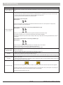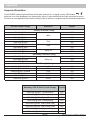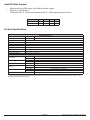
1
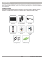
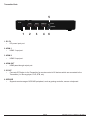
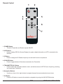
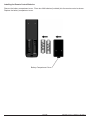
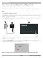
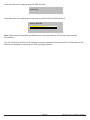
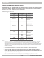
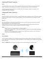
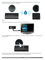
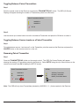
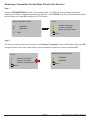
User Manual and Installation Guide
WIRELESS HD
MULTIMEDIA TRANSMIT TER
®
Models:
HDS-WHDI100T
ISSUED: 01-09-13 SHEET #: 180-9045-1
Contents
Safety Precautions ...........................................................................................................................................4
Important Information ......................................................................................................................................5
Unit Care Recommendations ..........................................................................................................................5
Introduction.......................................................................................................................................................6
Package Contents ..........................................................................................................................................6
Product Overview .............................................................................................................................................7
Transmitter .....................................................................................................................................................7
Remote Control ..............................................................................................................................................9
Installation.......................................................................................................................................................11
Pairing The Transmitter To An Existing Wireless HD Multimedia Kit ............................................................ 11
Alternate Pairing Option ...............................................................................................................................13
AV Device Setup...........................................................................................................................................15
IR Flasher Setup ..........................................................................................................................................15
Wall Mounting the HDS-WHDI100T (Optional) ............................................................................................16
Operation.........................................................................................................................................................17
Powering up the Multiple Transmitter System ..............................................................................................17
Indicator Lights Decoded ..............................................................................................................................17
Checking IR Flasher Frequency ...................................................................................................................18
Changing IR Flasher Frequency ..................................................................................................................18
Toggling Between Paired Transmitters .........................................................................................................20
Toggling Between Source Inputs on a Paired Transmitter ...........................................................................20
Renaming Paired Transmitter .......................................................................................................................20
Removing a Transmitter that Has Been Paired to the Receiver ..................................................................22
Troubleshooting .............................................................................................................................................23
Appendix .........................................................................................................................................................24
Supported Resolution ...................................................................................................................................24
Audio Bit Rate Support .................................................................................................................................25
Product Specifications ..................................................................................................................................25
Limited Warranty ............................................................................................................................................30
Wireless HD Multimedia System Offering ....................................................................................................31
Contact Information .......................................................................................................................................32
3 of 34
ISSUED: 01-09-13 SHEET #: 180-9045-1
Safety Precautions
WARNING!
RISK OF
ELECTRICAL
SHOCK
DO NOT OPEN
WARNING:
TO REDUCE THE RISK OF ELECTRICAL
SHOCK DO NOT REMOVE THE COVER.
NO USER-SERVICEABLE PARTS
ARE INSIDE. REFER SERVICING TO
QUALIFIED PERSONNEL
• Power to the units must be switched off before any work is undertaken, such as any AV device connection
or TV connection.
• To prevent electric shock, make sure to use the supplied DC adapters as power supply to the Transmitter
and Receiver.
• Be sure the power cord is routed so that it will not be stepped on or pinched by heavy items.
• Avoid overloading electrical outlets or extension cords which otherwise could result in electric shock or fire.
• Disconnect the product from the power source if it is left unattended for an extended period of time, and to
protect the product from lightning.
• To reduce the risk of electric shocks or fire, always disconnect the power cord from the power outlet when
you are not using the product for an extended period of time.
• This product should not be exposed to dripping or splashing liquids. No object filled with liquids, such as
vases, should be placed on the product.
• To avoid electric shock, never stick anything in the slots on the case or remove the cover.
• Place the product on a flat, hard and stable surface.
• Do not block the ventilation slots on the product or place any heavy object on the top cover. Blocking the
airflow could damage the product. Arrange components so that air can flow freely around the product.
Ensure that there is adequate ventilation if the product is placed in a cabinet. Put the products in a properly
ventilated area, away from direct sunlight or any source of heat.
• To reduce the risk of fire or electric shock, do not expose the product to water or moisture.
• This product is intended for indoor use only.
• This document may be modified without any notice.
4 of 34
ISSUED: 01-09-13 SHEET #: 180-9045-1
Important Information
• Never use this product in an aircraft or a medical facility as it can cause interference or an undesirable
effect.
• The use of this product in the following locations may result in abnormal video and audio output (noise,
blocked image...etc,).
• When the product is placed near a refrigerator or metal structure.
• When the environment consists of walls made of concrete.
• A cluttered room where the wireless signals may be blocked.
• This product has been tested and manufactured to comply with each country’s safety rules. However, there
is no guarantee that interference will not occur in some installations. If interference happens, decrease the
distance between the Transmitter and Receiver (Receiver not included).
• This product may interfere with 5GHz wireless devices.
• Optimal use of this product is for in-room/multi-room applications.
• Any changes or modifications not expressly approved by the manufacturer of this device could void the
product warranty.
• This equipment must be installed and operated in accordance with the provided instructions. The
Transmitter must be installed to provide a separation distance of at least 8” (20cm) from all persons and
must not be operating near or in conjunction with any other Transmitter. End users and installers must
be provided with installation instructions and Transmitter operating conditions for satisfying RF exposure
compliance.
• This device should be used only as specified within this manual to meet RF exposure requirements. Use of
this device in a manner inconsistent with this manual could lead to excessive RF exposure conditions.
Unit Care Recommendations
To clean, use a soft, dry cloth only. Do not use water or other cleaning products as they may cause electrical
failure or damage the surface of the product.
5 of 34
ISSUED: 01-09-13 SHEET #: 180-9045-1
Introduction
The PeerAir™ Wireless HD Multimedia Transmitter expands your current Wireless HD Multimedia System to
deliver uncompressed Full HD 1080p, as well as all 3D content to your existing HDTV wirelessly from additional
source components.
Package Contents
Ensure that the following items are present in the package. If any items are missing or damaged, please call
Peerless-AV Customer Care at 1-800-865-2112. (available 7:00am - 7:00pm (CST) Monday - Friday).
Transmitter
DC Power Adapter
IR Flasher
User Manual and Installation Guide
Quick Start Guide
WIRELESS HD
Model No. HDS-WHDI100
MULTIMEDIA SYSTEM
®
What’s in the Box
WIRELESS HD
- DC power adapter
- Mini USB power adapter
- Quick start guide
- User manual
- Transmitter
- Receiver
- IR Flasher, 3ft (1m)
- HDMI cable, 5ft (1.5m)
- Remote control (battery included)
TRANSMIT TER
Hardware Identification
Transmitter (rear view)
1
DC 5V
Receiver (rear view)
2
3
4
HDMI 1
HDMI 2
HDMI OUT
5
1
2
3
HDMI
IR OUT
SERVICE
6
1. DC 5V
2. HDMI 1
3. HDMI 2
1. Mini USB DC IN
2. HID USB
3. HDMI OUT
4. HDMI OUT
5. IR OUT
6. HID USB / SERVICE
Installation and Setup
OK
1
Transmitter
Step 1
Blu-ray Disc™ Player
Connect one end of an HDMI cable (not included) into the HDMI 1 port on the
Transmitter and the other end into the HDMI port on your AV device. Repeat the
above step to connect an additional AV device to the HDMI 2 port.
Step 2 (Optional pass-through connection)
Connect one end of an HDMI cable (not included) into the HDMI OUT port on the
Transmitter and the other end into the HDMI port on your HDTV.
®
3
2
Step 3
1
Connect one end of the DC power adapter into the DC 5V port on the Transmitter
and plug into a power outlet.
HD Media Player
Receiver
1
Step 1
Connect one end of the HDMI cable (1) to the HDMI OUT port on the
Receiver and connect the other end of the HDMI cable (1) to the HDMI port
on the HDTV.
Models:
HDS-WHDI100T
Step 2
HDTV
ISSUED: 01-09-13 SHEET #: 180-9045-1
Remote Control
Manual
Mounting Hardware
Connect the mini USB end of the of the DC power adapter (2) into the Mini
USB DC IN on the Receiver and plug into a power outlet.
2
Quick Start
Guide
AAA Batteries (2)
6 of 34
ISSUED: 01-09-13 SHEET #: 180-9045-1
Product Overview
Transmitter
Transmitter Top
2
3
1
1
2
1. POWER Button
•
Press to turn the Transmitter ON/OFF. The indicator light in the power button will be illuminated blue
when the power is on, glows red in standby mode, and glows purple in pairing mode.
2. SOURCE Selection Button
•
Press to toggle AV device inputs.
3. Source Indicator Lights
•
The source indicator lights will be illuminated to show current input selected.
7 of 34
ISSUED: 01-09-13 SHEET #: 180-9045-1
Transmitter Back
5
DC 5V
HDMI 1
HDMI 2
HDMI OUT
IR OUT
SERVICE
1
2
3
4
6
1. DC 5V
•
DC power input port.
2. HDMI 1
•
HDMI 1 input port.
3. HDMI 2
•
HDMI 2 input port.
4. HDMI OUT
•
HDMI pass-through output port.
5. IR OUT
•
Connects IR Flasher to the Transmitter for remote control of AV devices which are connected to the
Transmitter (i.e. Blu-ray player, DVD, STB, etc).
6. SERVICE
•
Supports remote usage of USB HID peripheral, such as gaming controller, mouse or keyboard.
8 of 34
ISSUED: 01-09-13 SHEET #: 180-9045-1
Remote Control
1
2
5
3
4
OK
6
7
1. POWER Button
•
Turns the Transmitter and Receiver power ON/OFF.
2. INFO Button
•
Press to display OSD (On Screen Display) for system related information on HDTV connected to the
Receiver.
3. IR Button
•
Press to change the IR Flasher frequency to meet the AV device’s requirement.
4. SOURCE Button
•
Press to toggle between AV devices connected to the Transmitter.
5. TRANSMITTER NO. Button
•
Press to select the transmitter selection menu, and allows access to SETUP menu for pairing, removing
and renaming a Transmitter.
6. Navigation Buttons
•
Use the up, down, left or right buttons to navigate through the menus and select menu items.
7. OK Button
•
Press the OK button to execute the selection navigated to by using the NAVIGATION buttons.
9 of 34
ISSUED: 01-09-13 SHEET #: 180-9045-1
Installing the Remote Control Batteries
Remove the battery compartment cover. Place two AAA batteries (included) into the remote control as shown.
Replace the battery compartment cover.
Battery Compartment Cover
10 of 34
ISSUED: 01-09-13 SHEET #: 180-9045-1
Installation
Pairing The Transmitter To An Existing Wireless HD Multimedia Kit
Note: The system will allow up to 4 Transmitters to be paired to 1 Receiver.
Note: If the following steps are not followed in the order listed, the Transmitter will not enter pairing mode.
Step 1
A. Plug the power adapter into a wall outlet.
B. Press and hold the POWER button on the Transmitter. While holding the Transmitters POWER button, plug
the power adapter into the Transmitter.
C. Hold the POWER button until the Transmitters power LED is illuminated purple (about 10-12 seconds). The
source LED will be blinking blue.
A
C
B
DC 5V
2
1
Step 2
A. Using the remote control provided with the Transmitter, point the remote control at the Receiver and press
the ON button to turn on the Receiver.
B. Press the TRANSMITTER NO. button on the remote control. The OSD (On Screen Display) will appear
showing the number of Transmitters paired to the Receiver.
Select TransmiƩer Number:
WHD200-1
WHD200-2
SETUP
Note: The OSD will only show Transmitters (denoted by WHD200-1, 2...) that are paired to the Receiver.
11 of 34
ISSUED: 01-09-13 SHEET #: 180-9045-1
C. Select SETUP using the up or down buttons on the remote control and Press OK to display the SETUP
screen.
SETUP:
Select TransmiƩer Number:
Add New TransmiƩer
Remove TransmiƩer
Modify TransmiƩer Name
WHD200-1
WHD200-2
SETUP
Return
D. Ensure that the LED light on the Transmitter that is being paired is illuminated purple then Select Add New
Transmitter from the OSD menu and press OK on the remote control.
SETUP:
2
Add New TransmiƩer
Remove TransmiƩer
Modify TransmiƩer Name
1
Return
E. At this time the Receiver will search for a Transmitter to pair to. When the Receiver finds and pairs to a
Transmitter, the system will reboot. When the power light is solid blue and the source light is blinking blue, the
system is paired (this process takes about 60 seconds).
NOTE: When both the Transmitter and Receiver are in pairing mode they will find each other and pair
automatically.
12 of 34
ISSUED: 01-09-13 SHEET #: 180-9045-1
Alternate Pairing Option
You can use this alternate method as a way to pair the Transmitter to the Receiver without using the Remote
Control.
Note: If the following steps are not followed in the order listed, the unit will not enter pairing mode.
Step 1
Follow Step 1 under Pairing and Installing the Transmitter to Already Existing Wireless HD Multimedia
Kit.
Step 2
Enter paring mode on the Receiver side by using the following method:
A. Plug the power adapter into a wall outlet.
B. Press and hold the POWER button on the Receiver. While holding the Receivers POWER button, plug the
power adapter into the Receiver unit.
C. Hold the POWER button until the Receiver POWER LED is illuminated purple (about 5 seconds).
A
C
B
SOURCE
1
2
13 of 34
ISSUED: 01-09-13 SHEET #: 180-9045-1
When the Receiver is in pairing mode the OSD will show:
Searching….
When both units are in pairing mode, and have found each other the OSD will show:
Adding WHD200
Note: When both the Transmitter and Receiver are in pairing mode they will find each other and pair
automatically.
The new Transmitter and the current Receiver units are now paired. Ensure that both the Transmitter and the
Receiver are powered on and the power LED is glowing solid blue.
14 of 34
ISSUED: 01-09-13 SHEET #: 180-9045-1
AV Device Setup
Step 1
A. Connect HDMI cable (not included) from AV device's HDMI out port to Transmitter's HDMI 1 port. Repeat for
HDMI 2 port if a second AV device is to be connected.
B. (Optional) If connecting to HDTV using wired connection, plug HDMI cable (not included) from Transmitter's
HDMI OUT port to HDTV's HDMI in port.
C. (Optional) If connecting to PC for remote usage of USB HID peripheral, such as gaming controller, mouse
or keyboard, plug mini USB-to-USB Type A cable (not included) from Transmitter's SERVICE port to PC's USB
OUT port.
Note: Ensure power adapter is plugged in.
DC 5V
HDMI 1
HDMI 2
HDMI OUT
IR OUT
SERVICE
A
C
B
PC
HDTV
A
HD Media Player
HD Projector
Blu-ray Player
IR Flasher Setup
Step 2
Connect the IR Flasher into the IR OUT port of the Transmitter. Find the IR window on the AV device and
adhere the IR Flasher eye on top of the IR window.
When the IR Flasher is connected, up to two AV devices can be controlled from Receiver location.
DC 5V
HDMI 1
HDMI 2
HDMI OUT
IR OUT
SERVICE
15 of 34
ISSUED: 01-09-13 SHEET #: 180-9045-1
Wall Mounting the HDS-WHDI100T (Optional)
The Transmitter can be mounted to a wall using the keyhole mounting slots located on the back of the unit.
Note: Wall mounting the Transmitter will reduce IR functionality.
Step 1
Transfer the dimensions shown below to the desired mounting location on the wall and mark with a pencil.
5.55" (141mm)
Step 2
Using the marks as a guide, drill two 7/32" (5mm) holes. Insert the supplied anchors into the holes. Using a
screwdriver, install the mounting screws into the anchors, leaving 1/4" (6mm) of space between the head of the
screw and the wall. Place the Transmitter over the screws and slide down into position.
Anchor
Wall
Screw
1/4" (6mm)
Wall
16 of 34
ISSUED: 01-09-13 SHEET #: 180-9045-1
Operation
Powering up the Multiple Transmitter System
When powering up a multi-Transmitter system, the Transmitter that will turn ON when using the remote pointing
at the Receiver will be the Transmitter that the Receiver is set too. When the source Transmitter is changed on
the Receiver unit, the new Transmitter will turn on automatically.
Indicator Lights Decoded
Power Indicator
Light
Source Indicator
Light
Solid Red
Off
Blinking Blue
Blinking
Description
Power saving mode.
Transmitter and Receiver
start up times are between
15 to 20 seconds.
During warm-up, if link is
not established after 80
seconds, see Notes below.
Blinking Blue
Blinking
Solid Blue
Blinking
(Quickly)
No input from selected
source
(see Notes below)
Solid Blue
Blinking
(Slowly)
Video format not
recognized
(see Notes below)
Solid Blue
Solid Blue
Video format is recognized
Blinking Purple
Blinking - Transmitter
Solid - Receiver
Pairing Mode
Notes:
•
If wireless connection is not established after 80 seconds, the Transmitter is out of range. Verify that
the range between the Transmitter and Receiver is within specifications and adjust or shorten the
distance between your Transmitter and Receiver. The maximum transmission range for 1080p HD and
3D content is up to 100 ft. (30m) line of sight and 30 ft. (9m) through one structure. The ideal minimum
range is 6.5 ft. (2m).
•
Ensure that the source device is powered on and the Transmitter is set to the proper input.
•
If there is no video showing on the output device and the on screen display states "Not Supported
Format", this is an indication that the video frame rate from the AV device is not supported. Refer to the
Supported Resolutions section of the Appendix.
•
Each Transmitter and Receiver should ideally be at least 6.5 ft. (2m) away from one another.
17 of 34
ISSUED: 01-09-13 SHEET #: 180-9045-1
Checking IR Flasher Frequency
Step 1
Using the remote control for your AV device, point the remote control at the Receiver and press the Power
button. If the power on the AV device turns ON/OFF, the remote frequency is set for the AV device.
If the power on the AV device does not turn ON/OFF, the remote frequency needs to be changed. See
Changing IR Flasher Frequency.
Changing IR Flasher Frequency
Step 1a
Using the remote provided with this system, press the IR button once to display the active IR Flasher frequency.
Press the IR button again to change to the next frequency. The IR Flasher frequency will change with each
button press.
Step 1b
After changing to the next frequency, press the Power button on your AV device’s remote control. If the AV
device turns ON/OFF, the remote frequency is set.
If there is no action from your AV device, use the remote provided with this system to change to the next
frequency and repeat the above steps until a proper IR frequency is located.
Notes:
•
One IR Flasher eye is to be used for one component device.
•
The IR sensor supports 35KHz - 58KHz carrier frequencies. Therefore, it is possible that some devices
may not be supported.
•
Most often, the IR window is easier to locate with direct light shining on sections of the front panel of
your AV device (a small flashlight works well).
Step 2
Stand -By Mode
If the Transmitter and Receiver are in Standby mode (both Power indicator lights of Transmitter and Receiver
are lit in red), press the Power button on either the Receiver or on the remote control to wake up the Transmitter
and the Receiver.
Note: The HDMI OUT pass through port is always on even if the Transmitter is in standby mode.
18 of 34
ISSUED: 01-09-13 SHEET #: 180-9045-1
During warm-up, the Power indicator light will blink blue until the signal link between the Transmitter and
Receiver is established, between 15 - 20 seconds.
Step 3
Check that your output device is turned on and set to the proper HDMI input.
Y/Pb/Pr
Video
HDMI
HDMI
RGB
S-Video
HDTV
Press the SOURCE button on the remote control, or on the top of Transmitter or Receiver, to select the desired
AV device input.
2 1
If all operation is normal, the Power and SOURCE indicator lights will be illuminated blue. Refer to the table
containing detailed indicator light and OSD description of Transmitter/Receiver.
19 of 34
ISSUED: 01-09-13 SHEET #: 180-9045-1
Toggling Between Paired Transmitters
Step 1
Point the remote control at the Receiver and press the TRANSMITTER NO. button. The OSD (On Screen
Display) will appear showing the number of Transmitters paired to the Receiver.
Select TransmiƩer Number:
WHD200-1
WHD200-2
SETUP
Step 2
Use the remote up or down button to scroll to the desired Transmitter and press the OK button to select it.
Toggling Between Source Inputs on a Paired Transmitter
Step 1
To toggle between source 1 and source 2 on the Transmitter, point the remote at the Receiver and press the
SOURCE button on the remote control or on the unit.
Renaming Paired Transmitter
Step 1
Press the TRANSMITTER NO. button on the remote control. The OSD (On Screen Display) will appear
showing the number of Transmitters paired to the Receiver. Select SETUP using the up or down buttons on the
remote control and Press OK to display the SETUP screen.
SETUP:
Select TransmiƩer Number:
Add New TransmiƩer
Remove TransmiƩer
Modify TransmiƩer Name
WHD200-1
WHD200-2
SETUP
Return
Note: The OSD will only show Transmitters (denoted by WHD200-1, 2...) that are paired to the Receiver.
20 of 34
ISSUED: 01-09-13 SHEET #: 180-9045-1
Step 3
Use the up or down buttons on the remote to select Modify Transmitter Name from the OSD options then
press OK.
SETUP:
Add New TransmiƩer
Remove TransmiƩer
Modify TransmiƩer Name
Return
Step 4
Using the up or down buttons on the remote select the desired Transmitter to rename and press OK.
Step 5
Use the left or right buttons on the remote to move the cursor. Use the up or down buttons on the remote to
scroll through the letters of the alphabet. Press the IR button to delete/move the cursor back.
Step 6
When the name has been set press OK.
Step 7
To exit the menu, press the Transmitter NO. button.
21 of 34
ISSUED: 01-09-13 SHEET #: 180-9045-1
Removing a Transmitter that Has Been Paired to the Receiver
Step 1
Press the TRANSMITTER NO. button on the remote control. The OSD (On Screen Display) will appear
showing the number of Transmitters paired to the Receiver. Select SETUP using the up or down buttons on the
remote control and Press OK to display the SETUP screen.
SETUP:
Select TransmiƩer Number:
Add New TransmiƩer
Remove TransmiƩer
Modify TransmiƩer Name
WHD200-1
WHD200-2
SETUP
Return
Step 2
Use the up or down buttons on the remote to select Remove Transmitter from the OSD options then press OK.
Using the remote control up or down buttons, select the desired Transmitter to remove and press OK.
Remove Recoded TransmiƩer:
SETUP:
WHD200-1
WHD200-2
Add New TransmiƩer
Remove TransmiƩer
Modify TransmiƩer Name
Return
Return
22 of 34
ISSUED: 01-09-13 SHEET #: 180-9045-1
Troubleshooting
Problem
Solution
The power indicator light • Check the power connections on the Transmitter and Receiver to ensure they are properly inserted into a functioning power
does not light up.
outlet.
• Verify that the proper cables have been selected and installed between the Transmitter input and your AV device output.
• On the TV side (connected to the Receiver), select the HDMI as the input source.
• Verify the state of the Power and Source as indicated below:
Power Indicator Light Flashing Blue
OSD displayed:
* Ensure the transmission range between the Transmitter and Receiver is NOT over 100 ft. (30m) line of sight (LOS).
* Move the Transmitter closer to the Receiver.
Power Indicator Light Solid Blue + Slow Flashing SOURCE Indicator Light
OSD displayed :
No video is displayed on
your TV screen.
l ti and
d frame
f
* Ensure your video resolution
rate is supported and within the transmission range.
* Connect the AV device to your TV to check and modify the video format compatibility.
* Check that the resolution of your device is set to 1080p, 1080i, 720p,or 480p. Refer to the Supported Resolution section of
the Appendix.
Power Indicator Light Solid Blue + Fast Flashing SOURCE Light
OSD displayed :
Poor picture quality or
intermittent video.
No audio.
IR Flasher can’t control
AV device.
No 3D video output
es are connected
conn
* Ensure the proper cables
between the Transmitter and your AV devices.
* Ensure your AV devices connected to the Transmitter are powered on.
* Ensure the proper cables are connected between the Receiver and your HDTV.
• Check that the resolution of your device is set to 1080p, 1080i, 720p, or 480p. Please refer to the Supported Resolution
section of the Appendix.
• Ensure the transmission distance is less than 100 ft. (30m) line of sight (LOS).
• Check your HDTV’s volume is properly set and not set in "MUTE" mode.
• Check if your AV device’s audio volume has been turned up.
• Ensure the audio bit rate of the AV device can be supported. Refer to the Audio Bit Rate Support section of the Appendix.
• Check the location and position of the IR Flasher on the AV device. Refer to IR Flasher Set Up in the Setup and Operation
section of this manual.
• Change the IR Flasher frequency to meet the AV device’s requirement. Refer to On Screen Display (OSD) Functions in the
Setup and Operation section of this manual.
OSD displayed : Transmitter
and/or Receiver
* Check that both TVs support 3D video format. If either TV only supports 2D format, then 3D output will not be supported.
* If displaying 3D video on the HDTV which supports 3D video, turn off the 2D HDTV and cycle the power on 3D HDTV (turn
OFF, then ON). Set the AV player to 3D video format output for the 3D display.
* Check that the 3D AV device is set to 24p
23 of 34
ISSUED: 01-09-13 SHEET #: 180-9045-1
Appendix
Supported Resolution
If the SOURCE indicator light continues to blink blue (slower than “no signal” mode); OSD display:
,
and there is no video displayed or the video quality is poor, it may indicate that the video frame rate
e from your
you
AV device is not supported. Ensure that the timing of the AV device is compliant with the standards listed below:
2D Video Format Timings
Resolution
Support
Primary CEA Video Timing
640x480p @ 60Hz
YES
480p
720x480p @ 60Hz
1280x720p @ 50Hz
1280x720p @ 60Hz
1920x1080i @ 50Hz
1920x1080i @ 60Hz
1920x1080p @ 50Hz
1920x1080p @ 60Hz
YES
YES
YES
YES
YES
YES
YES
720p
1080i
1080p / 60
Secondary CEA Video Timing
1920x1080p @ 24Hz
1920x1080p @ 25Hz
1920x1080p @ 30Hz
640x480 @ 60 / 72.809Hz
800x600 @ 60 / 72.188Hz
1024x768 @ 60 / 70.069Hz
1280x768 @ 60 Hz
1280x1024 @ 60 Hz
1600x1200 @ 60Hz
YES
YES
YES
1080p / 24
VESA Timing (DVI only)
VGA
SVGA
XGA
WXGA
SXGA
UXGA
YES
YES
YES
YES
YES
YES
Mandatory CEA 3D Video Format Timings
Support
1280x720p @ 50Hz Top-and-Bottom
YES
1280x720p @ 50Hz Frame packing
YES
1280x720p @ 60Hz Top-and-Bottom
YES
1280x720p @ 60Hz Frame packing
YES
1920x1080i @ 50Hz Side-by-Side (Half)
YES
1920x1080i @ 60Hz Side-by-Side (Half)
YES
1920x1080p @ 24Hz Top-and-Bottom
YES
1920x1080p @ 24Hz Frame packing
YES
24 of 34
ISSUED: 01-09-13 SHEET #: 180-9045-1
Audio Bit Rate Support
•
•
•
Digital audio from HDMI inputs: Up to 6Mbit/s bit-rate support.
Supports 5.1 digital audio.
2-channel PCM: 16 - 24 bits audio sampling with 32 - 96KHz sampling rate as below:
2 Channel PCM 32KHz 44.1KHz 48KHz 96KHz
16 bits
YES
YES
YES
YES
24 bits
YES
YES
YES
YES
Product Specifications
HDS-WHDI100T
Supported Video Resolutions
Supported Audio Formats
Transmission Distance
Antenna
Latency
Operating Frequencies
Power Supply
Operating Temperature
Operating Relative Humidity
Storage Temperature
Interface
AV Interface
IR Control
Power Interface
Buttons
LEDs
Dimensions (W) x (L) x (H)
1080p, 1080i, 720p, 480p
AC3 and DTS
HDMI Input
Digital Audio
Up to 100 feet line of sight (LOS)*
High Performance Internal Antennas
Zero Latency (.001sec)
4.9-5.9 GHz (Includes DFS and NON-DFS)
100-240V AC in, 5V DC power adapter
32F -104F (0 - 40°C)
10% - 80%
14°F – 131°F (10 - 55°C)
Transmitter
HDMI Input
HDMI Output
IR Sensor
IR Flasher
Power Input
Power Button
Source Button
Power LED
Source LED
2 x Type A
1 x Type A
Yes
Yes
5V DC
Yes (1 x tact switch)
Yes (1 x tact switch)
1 X LED (two tone: Blue/Red)
2 x LED (Blue)
7.17" x 3.80" x 1.24" (182 x 96.5 x 31.5mm)
* Transmission distance will depend on actual environment. Distance based on line-of-sight. Structures constructed of steel, wood, concrete, or/and
brick may decrease transmission distance.
25 of 34
ISSUED: 01-09-13 SHEET #: 180-9045-1
Federal Communication Commission Interference Statement
This device complies with Part 15 of the FCC Rules. Operation is subject to the following two conditions: (1)
This device may not cause harmful interference, and (2) this device must accept any interference received,
including interference that may cause undesired operation.
This equipment has been tested and found to comply with the limits for a Class B digital device, pursuant
to Part 15 of the FCC Rules. These limits are designed to provide reasonable protection against harmful
interference in a residential installation. This equipment generates, uses and can radiate radio frequency
energy and, if not installed and used in accordance with the instructions, may cause harmful interference to
radio communications. However, there is no guarantee that interference will not occur in a particular installation.
If this equipment does cause harmful interference to radio or television reception, which can be determined
by turning the equipment off and on, the user is encouraged to try to correct the interference by one of the
following measures:
- Reorient or relocate the receiving antenna.
- Increase the separation between the equipment and receiver.
- Connect the equipment into an outlet on a circuit different from that to which the receiver is connected.
- Consult the dealer or an experienced radio/TV technician for help.
FCC Caution: Any changes or modifications not expressly approved by the party responsible for compliance
could void the user's authority to operate this equipment. This transmitter must not be co-located or operating
in conjunction with any other antenna or transmitter. Transmitter (TX) operations in the 5.15-5.25GHz band are
restricted to indoor usage only. Receiver operation within 5.15 ~ 5.25GHz / 5.47 ~ 5.725GHz frequency range,
it is restricted to indoor environment. The band from 5600-5650MHz will be disabled by the software during the
manufacturing and cannot be changed by the end user. This device meets all the other requirements specified
in Part 15E, Section 15.407 of the FCC Rules.
Radiation Exposure Statement:
The product comply with the FCC portable RF / radiation exposure limit set forth for an uncontrolled
environment and are safe for intended operation as described in this manual. The further RF exposure
reduction can be achieved if the product can be kept as far as possible from the user body or set the device to
lower output power if such function is available.
The USB dongle transmitter is approved for use in typical laptop computers. To comply with FCC RF exposure
requirements, it should not be used in other devices or certain laptop and tablet computer configurations
where the USB connectors on the host computer are unable to provide or ensure the necessary operating
configurations intended for the device and its users or bystanders to satisfy RF exposure compliance
requirements. Receiver should be installed and operated with minimum distance 20cm between the radiator &
your body. Note: The country code selection is for non-US model only and is not available to all US model. Per
FCC regulation, all WiFi product marketed in US must fixed to US operation channels only.
26 of 34
ISSUED: 01-09-13 SHEET #: 180-9045-1
Declaration of Conformity
This device complies with Part 15 of the FCC Rules. Operation is subject to the following two conditions:
1. This device may not cause harmful interference, and
2. This device must accept any interference received, including interference that may cause undesired
operation.
EMI (Electro Magnetic Interference) tested.
EN 55022 Information technology equipment---Radio disturbance characteristics--- Limits and methods of measurement
EN 61000-3-2 Electromagnetic compatibility (EMC)--Part 3-2: Limits---Limits for harmonic current emissions (equipment input current up to and including 16 A per
phase)
EN 61000-3-3 Electromagnetic compatibility (EMC)--Part 3: Limits---Section 3: Limitation of voltage changes, voltage fluctuations and flicker in public low-voltage
supply systems, for equipment with rated current <16 A per phase and not subject to conditional connection
EN 55024 Information technology equipment---Equipment---Immunity characteristics---Limits and methods of measurement
EN 301 489-1
Electromagnetic compatibility and Radio spectrum Matters (ERM); Electro Magnetic Compatibility (EMC)
standard for radio equipment and services;
Part 1: Common technical requirements
EN 301 489-17
Electromagnetic compatibility and Radio spectrum Matters (ERM); Electro magnetic Compatibility(EMC)
standard for radio equipment;
Part 17: Specific conditions for 2.4GHz wideband transmission systems, 5GHz high performance RLAN
equipment and 5.8GHz Broadband Transmitting Systems
EN 60065 Audio, video and similar electronic apparatus—Safety requirements
27 of 34
ISSUED: 01-09-13 SHEET #: 180-9045-1
Industry Canada Statement
This device complies with RSS-210 of the Industry Canada Rules. Operation is subject to the following two
conditions: (1) This device may not cause harmful interference, and (2) this device must accept any interference
received, including interference that may cause undesired operation.
Ce dispositif est conforme à la norme CNR-210 d'Industrie Canada applicable aux appareils radio exempts de
licence. Son fonctionnement est sujet aux deux conditions suivantes: (1) le dispositif ne doit pas produire de
brouillage préjudiciable, et (2) ce dispositif doit accepter tout brouillage reçu, y compris un brouillage susceptible
de provoquer un fonctionnement indésirable.
Caution :
(i) the device for operation in the band 5150-5250 MHz is only for indoor use to reduce the potential for harmful
interference to co-channel mobile satellite systems;
(ii) the maximum antenna gain permitted for devices in the bands 5250-5350 MHz and 5470-5725 MHz shall
comply with the e.i.r.p. limit; and
(iii) the maximum antenna gain permitted for devices in the band 5725-5825 MHz shall comply with the e.i.r.p.
limits specified for point-to-point and non point-to-point operation as appropriate.
(iv) Users should also be advised that high-power radars are allocated as primary users (i.e. priority users) of
the bands 5250-5350 MHz and 5650-5850 MHz and that these radars could cause interference and/or damage
to LE-LAN devices.
Avertissement:
Le guide d’utilisation des dispositifs pour réseaux locaux doit inclure des instructions précises sur les
restrictions susmentionnées, notamment :
(i) les dispositifs fonctionnant dans la bande 5 150-5 250 MHz sont réservés uniquement pour une utilisation à
l’intérieur afin de réduire les risques de brouillage préjudiciable aux systèmes de satellites mobiles utilisant les
mêmes canaux;
(ii) le gain maximal d’antenne permis pour les dispositifs utilisant les bandes 5 250-5 350 MHz et 5 470-5 725
MHz doit se conformer à la limite de p.i.r.e.;
(iii) le gain maximal d’antenne permis (pour les dispositifs utilisant la bande 5 725-5 825 MHz) doit se conformer
à la limite de p.i.r.e. spécifiée pour l’exploitation point à point et non point à point, selon le cas.
(iv) De plus, les utilisateurs devraient aussi être avisés que les utilisateurs de radars de haute puissance sont
désignés utilisateurs principaux (c.-à-d., qu’ils ont la priorité) pour les bandes 5 250-5 350 MHz et 5 650-5 850
MHz et que ces radars pourraient causer du brouillage et/ou des dommages aux dispositifs LAN-EL.
28 of 34
ISSUED: 01-09-13 SHEET #: 180-9045-1
Radiation Exposure Statement:
The product comply with the Canada portable RF / IC radiation exposure limit set forth for an uncontrolled
environment and transmitter are safe for intended operation as described in this manual. The further RF
exposure reduction can be achieved if the product can be kept as far as possible from the user body or set
the device to lower output power if such function is available. Receiver should be installed and operated with
minimum distance 20cm between the radiator & your body.
Déclaration d'exposition aux radiations:
Le produit est conforme aux limites d'exposition pour les appareils portables RF pour les Etats-Unis et le
Canada établies pour un environnement non contrôlé.
Le produit est sûr pour un fonctionnement tel que décrit dans ce manuel. La réduction aux expositions RF peut
être augmentée si l'appareil peut être conservé aussi loin que possible du corps de l'utilisateur ou que le
dispositif est réglé sur la puissance de sortie la plus faible si une telle fonction est disponible.
Cet équipement est conforme aux limites d'exposition aux rayonnements IC établies pour un environnement
non contrôlé. Cet équipement doit être installé et utilisé avec un minimum de 20 cm de distance entre la source
de rayonnement et votre corps.
29 of 34
ISSUED: 01-09-13 SHEET #: 180-9045-1
Limited Warranty
Peerless Industries, Inc. (“Peerless-AV®”) warrants to original end-users of Peerless-AV® products that
Peerless-AV® products will be free from defects in material and workmanship, under normal use, for the periods
listed below, from the date of purchase by the original end-user. At its option, Peerless-AV® will repair or replace
with new or refurbished products or parts, or refund the purchase price of, any Peerless-AV™ product which
fails to conform with this warranty.
In no event shall the duration of any implied warranty of merchantability or fitness for a particular
purpose be longer than the period of the applicable express warranty set forth above. Some states do not
allow limitations on how long an implied warranty lasts, so the above limitation may not apply to you.
This warranty does not cover damage caused by (a) service or repairs by the customer or a person who is not
authorized for such service or repairs by Peerless-AV®, (b) the failure to utilize proper packing when returning
the product, (c) incorrect installation or the failure to follow Peerless-AV®’s instructions or warnings when
installing, using or storing the product, or (d) misuse or accident, in transit or otherwise, including in cases
of third-party actions and force majeure. This warranty also does not cover corrosion or rust resulting from
damaged, scratched or chipped paint or other surfaces.
In no event shall Peerless-AV® be liable for incidental or consequential damages or damages arising
from the theft of any product, whether or not secured by a security device which may be included with
the Peerless-AV® product. Some states do not allow the exclusion or limitation of incidental or consequential
damages, so the above limitation or exclusion may not apply to you.
This warranty is in lieu of all other warranties, express or implied, and is the sole remedy with respect to product
defects. No dealer, distributor, installer or other person is authorized to modify or extend this Limited Warranty
or impose any obligation on Peerless-AV® in connection with the sale of any Peerless-AV® product.
This warranty gives specific legal rights, and you may also have other rights which vary from state to state.
Product
Mounts
Furniture
Cables
Cleaning Products
Electronic Products and components
30 of 34
Warranty Period
5 years
1 year
25 years
1 year
1 year
ISSUED: 01-09-13 SHEET #: 180-9045-1
Wireless HD Multimedia System Offering
Model
Description
HDS-WHDI100
Wireless HD Multimedia System
HDS-WHDI100T
Wireless HD Multimedia Transmitter
HDS-ASR1
Shelf for use with HDS-WHDI100 Receiver
HDS-PSR1
Projector Support for use with HDS-WHDI100
Receiver
EC-HD015F
1.5ft. (.5m) High speed HDMI Cable with
Ethernet
EC-HD025F
2.5ft. (.75m) High speed HDMI Cable with
Ethernet
EC-HD03F
3ft. (1m) High speed HDMI Cable with
Ethernet
DE-HD0075B
Delta 2.5ft (.75m) Premium High Speed
HDMI Cable with Ethernet
DE-HD01B
Delta 3ft (1m) Premium High Speed HDMI
Cable with Ethernet
31 of 34
ISSUED: 01-09-13 SHEET #: 180-9045-1
Contact Information
Customer Care
Need help with set up? Call Peerless-AV Customer Care
1-800-865-2112 (available 7:00am- 7:00pm CST, Monday - Friday), or email us at [email protected].
Peerless -AV
2300 White Oak Circle
Aurora, IL 60502 USA
www.peerless-av.com
peerair.peerless-av.com
32 of 34
ISSUED: 01-09-13 SHEET #: 180-9045-1
Notes
Notes
Notes
2300 White Oak Circle,
Aurora, IL 60502 USA
1-800-865-2112
www.peerless-av.com
peerair.peerless-av.com
©2013 Peerless-AV. All rights reserved. Peerless-AV is a trademark of Peerless Industries, Inc.
Other parties’ marks are the property of their respective owners.