1
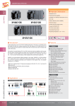
The i-7531 CAN Repeater
Quick Start User Guide
1. Introduction
This user guide describes how to implement the i-7531 module into
users’ applications in a quick and easy way. Therefore, it only provides the
basic concepts. If users want to know more detail information about the i7531, please refer to the user manual of i-7531 in the product CD or visit
our website as follow:
http://www.icpdas.com/products/Remote_IO/can_bus/i-7531.htm
The purpose of this document is focused on helping users to quickly
familiarize themselves with the i-7531 module. For example, users can
apply the i-7531 module as follow figure:
Backbone use
Backbone of CAN bus
i-7531
i-7531
CAN branch
i-7531
CAN branch
CAN branch
Electronic isolation
Extended use
i-7531
Original
CAN bus
i-7531
Extended
CAN bus
Extended
CAN bus
Electronic isolation
i-7531 CAN Repeater Quick Start User Guide (ver. 1.1, 2008/01/10) -----1
2. Hardware Structure
CAN Port 2
Status LED of Power
& Communication
CAN Port 1
Power Input
When the i-7531 is turned on, the status LED will be display with red
light. Moreover, when a message passes through i-7531, the status LED
will be twinkle once with yellow light while the red light is still on.
Note: Twinkling rate correlates with baud rate of CAN bus. Users may
see no twinkling when the twinkling period is too short because of
the higher baud rate of CAN bus. Besides, the yellow LED could
look like always on when bus loading is heavy.
i-7531 CAN Repeater Quick Start User Guide (ver. 1.1, 2008/01/10) -----2
3.
Terminator Resistor Setting
According to the ISO 11898 specifications, the CAN bus network must
be terminated by one terminal resistor (120Ω) on each end of CAN bus for
proper operation.
The JP2 of i-7531 is used for adjusting terminal resistor on CAN Port 1,
and the JP3 of i-7531 is used for adjusting terminal resistor on CAN Port 2.
Before setting terminal resistor of i-7531, user needs to open the
cover of i-7531 first. Those locations of JP2 and JP3 are shown as
following figure:
The following connection statuses present the condition if the terminal
resistor is enabled (default) or disabled.
Disable
(Deactivate)
4.
Enable
(Activate)
Configuration Installation
Step1: Modify JP2 and JP3 of i-7531 according to user’s application.
Step2: Connect two different CAN buses using i-7531 as follow figure:
i-7531 CAN Repeater Quick Start User Guide (ver. 1.1, 2008/01/10) -----3
FG (CAN_Shield)
CAN Bus 1
CAN_GND
CAN_H
CAN DEVICE
CAN_L
5
9
6
1
3
CAN Bus 2
CAN_L
Ground
CAN_H
+10V ~ +30V
CAN_GND
FG (CAN_Shield)
Note: Roughly speaking, wiring of CAN_GND and FG between CAN
devices can improve the capability of anti-interference of CAN
bus system in harsh environment, but this is not necessary.
For more Information about CAL_L, CAN_H, CAN_GND and FG
(CAN_Shield), please refer to user manual of i-7531.
i-7531 CAN Repeater Quick Start User Guide (ver. 1.1, 2008/01/10) -----4