1
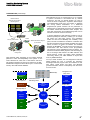
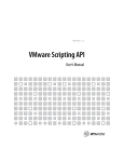
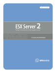
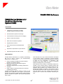
VM600 CMS Software
VM600 Series Software for
Condition Monitoring
System (CMS)
FEATURES
]
Configuration and operation of VM600
hardware (CMC16 and IOC16T cards)
]
Automatic data acquisition and storage
]
Limit exceedance checking and event logging
]
Online or offline data analysis
]
ANSI SQL 92 standard compatible
]
Graphical User Interface
]
Runs under Windows NT/2000/XP/2003
Server
]
Optional Air Gap Module for hydro-turbines
]
Optional Diagnostics Rule Box module
DESCRIPTION
t
f
a
r
d
t
s
r
i
F
Condition-based maintenance is a predictive methodology
that can be used to improve your asset/machinery
effectiveness. It enables you to:
]
]
]
]
CMS Software has a truly modular architecture that adapts
to your specific needs. It comprises of several software
modules for use with the VM600 series hardware. The steps
to follow are the configuration of parameters, data
acquisition and finally display the results for advanced
analysis and diagnosis of your machinery.
Improve equipment reliability through the effective
prediction of equipment failures
Minimise downtime through the planning and
scheduling of overhauls
Maximise component life by avoiding critical known
conditions
Utilise condition monitoring techniques to maximise
equipment performance
CMS Software has the ability to automatically adapt to the
criticality of the machine status by applying specific data
logging scenarios. The background mode is continuous lowresolution data acquisition. The scheduled mode is predefined high-resolution acquisition. The transient mode is
automatically detected and then transient data are acquired
when the speed is out of the "steady" state. Finally, the
manual mode is real-time data acquisition initiated by the
user.
Condition Monitoring Software (CMS) is based on this
principle and is dedicated to the support of technicians,
operators and engineers, enabling them to rapidly identify a
problem, evaluate the situation and determine appropriate
action to take.
© Vibro-Meter SA / 268-106 / 04.06 / E
1/7
Condition Monitoring System
VM600 CMS Software
DESCRIPTION (Continued)
VM600 Hardware
Protection and Condition
Monitoring Racks
CMS Software can run on a single host PC or on a number
of systems connected to the VM600 rack by network
connections. This lets you decide whether you need to
perform the entire configuration, acquisition, data analysis
and troubleshooting tasks from one location or distribute
them among several workstations. In a distributed
configuration,all specific functions can be performed on
dedicated PCs by appropriate personnel. This classification
also enables remote data collection and/or analysis, and
means that configuration and troubleshooting tasks can be
performed via remote access if necessary.
Interpretation & DIagnostics
Intranet
Ethernet
Hub
Modem
Host PC
Running CMS Software
Data Storage &
Management
t
s
ir
CMS Software takes advantage of the industry standard
platforms to allow total adaptability of the system. It runs
under Windows NT, 2000, XP or 2003 Server and has a
fully graphical interface for ease of use. Moreover, the SQLbased data management server allows you to communicate
with any other SQL-based database.
Key:
a
r
d
VM600 CMS Remote Support
by Vibro-Meter
F
On top of these modules, the new Diagnostics Rule Box
(DRB) enables the user to integrate his machinery
knowledge within the program rules, set conditions on realtime values, create alarms and alerts, and ultimately
generate automatic actions to adequately warn the user if
an event occurs.
Standard
(Basic Package)
VM600 Rack(s)
Optional Add-on
Modules
External Systems:
Turbine Control
System etc.
t
f
For further applications, CMS software provides a suite of
standard import/export interfaces, enabling you to transfer
data to/from any third party system. Your installation
benefits are thus the full flexibility and scalability of the
system, because it enables the correlation of vibration data
with other parameters that are already available from other
devices, so there is no need to re-measure. The available
interfaces are MODBUS® and OPC (Open Connectivity) for
communication with field devices, PLDs (Programable
Logic Devices), DCSs (Distributed Control Systems), etc.
The Microsoft standard DDE (Dynamic Data Exchange) is
used to exchange data between the CMS Software and
external devices. Finally, the ODBC (Open Database
Connectivity) allows your CMS database to import data
from any ODBC database.
Configuration and
Setup Tools:
Configuration
Editor
Communications and
Data Storage Tools:
VM600
Administrator
VMCom
Communications
Handler
Display and
Analysis Tools:
Mimic
Data Import/Export:
Data
Analyser
ODBC
Keyboard
Interface
Database
Server
Database
Browser
MODBUS
Event
Viewer
DDE
Diagnostics
Rule Box
OPC
© Vibro-Meter SA / 268-106 / 04.06 / E
Database
Air Gap
Module
2/7
Condition Monitoring System
VM600 CMS Software
DIMENSIONS
VM600 Administrator
The VM600 Administrator program is a "portal" providing quick and convenient access to all of the
CMS Software tools, as well as to a number of useful Windows system tools.
Mimic
The Mimic provides the operator with a customised, graphical view of the machinery being
monitored by the CMS Software system.
The types of data you can visualise directly from the Mimic are "live" data, i.e. current values and
current status of both the VM600 hardware and the "offline" systems, as well as user-requested
high-resolution data such as waveforms, spectra and orbit plots.
Data Analyser
The Data Analyser is used to display measurement data from the SQL database.
It takes data from selected data points defined in the database, applies user- or system-defined
filters to the data, and displays the data as a variety of graphs, plots and charts.
Typical filters that can be applied to data are time, alarm status, machine status, or a userconfigurable filter based on any speed, analog or digital data.
Database Browser
t
f
a
r
d
t
s
r
i
F
The Database Browser is used to display the content of the SQL database in graphical form.
It can display stored datasets, such as events, spectra, waveforms and orbits as intuitive time-line
representations, thus providing an effective overview of the measurement data that have been
collected. You can then quickly navigate to the dataset of interest using a set of independent
criteria (by point, type of data set, time or alarm state).
Event Viewer
Configuration Editor
The Event Viewer is used to view the events in the SQL database that may have been created
automatically by the system or as defined by users. It displays the available events in list form,
using colour coded, intuitive icons. The window shows either all events present in the database, or
you can choose to set and activate filter criteria in order to limit the displayed events.
The Configuration Editor is used to set up the required configuration of all aparameters of the
system, including the configuration details of each single output band, machine-specific
parameters for data logging or transient data and complete VM600 rack configurations.
It stores the system configuration inside the SQL database, from where it can be viewed or
changed by users with sufficient access rights.
It is also a starting point for the advanced configuration of the database, such as preparing the
database to accept "offline" data imported from external systems.
VMCom
The VMCom program handles the flow of data between VM600 racks and SQL databases. It
communicates with the CMS hardware and the SQL database.
This program can either be launched manually or configured as a system service; for this purpose
a special service setup utility is included that allows you to configure, create or delete a Windows
system service. This is the preferred way of communicating with VM600 hardware for permanent
system installations and dedicated on-line condition monitoring applications.
Table 1: CMS Software Application Modules (Sheet 1 of 2)
© Vibro-Meter SA / 268-106 / 04.06 / E
3/7
Condition Monitoring System
VM600 CMS Software
DIMENSIONS (Continued)
Diagnostics Rule Box
(optional)
The optional Diagnostics Rule Box is a powerful, fully automated, decision support system for
operators and machinery experts. Any information in a SQL database, including measurement
data and imported "offline" data, can be used to generate complex diagnostics rules. You can also
develop templates for standard diagnostics procedures and activate them for any item of
machinery.
This tool is based on the concept of fully customisable rules and scripts:
• Rules are composed of three elements:
- Input Level: Any number of customisable input criteria, such as exceedance checks, points' status and
counters, which are associated with either individual measurement points or groups of measurement
points.
- Logical Level: A freely-configurable assembly of logical combinations of Input Level elements.
- Action Level: Any number of user-defined actions that are executed based upon results from the Logical
Level.
t
f
• Scripts are assemblies of rules that are ready to be executed according to user-defined
parameters. Scripts can contain sequences, loops and branches, and allow you to customise
their execution according to the particular needs of the diagnostics rules.
a
r
d
• These three elements are interconnected using a user-friendly and intuitive graphical editor.
Simulation tools are provided to allow easy visual verification and testing of the rules, using
simple colour-coding techniques.
t
s
ir
Diagnostics rules are easy to adapt and enhance without affecting normal system operation.
The Diagnostics Server subsequently runs independently and performs the tasks defined in the
Diagnostics Rule Box, working in parallel with the normal data acquisition tasks of the system.
Air Gap Module
(optional)
F
The optional Air Gap Module (based on using VM600 CMS Hardware in a special configuration
with post-processing) allows you to monitor the gap between the rotor and stator in large hydrogenerator groups, thereby avoiding potentially destructive and costly failures of machinery.
The main functions of this module are to:
• Allow the long-term monitoring of the rotor/stator air-gap
• Measure rotor profile in one or more layers
• Generate alarms and alerts for each sensor installed on the machine
• Continue to process and interpret data in the event of one or more sensors becoming nonoperational
• Detect critical deformation of the rotor
• Perform long-term trend measurements
• Calculate the basic values that characterise the position and shape of the rotor and stator
The Air Gap Module can produce a variety of dedicated graphs, in addition to those produced by
the standard VM600 CMS Software (see Table 3).
Table 1: CMS Software Application Modules (Sheet 2 of 2)
© Vibro-Meter SA / 268-106 / 04.06 / E
4/7
Condition Monitoring System
VM600 CMS Software
DIMENSIONS (Continued)
With its optional add-on set of open-standard data interfaces, the CMS Software is capable of processing "offline data", i.e.
data that are not originally acquired using a VM600 Hardware but from other third party systems like field devices, PLD's, DCS,
etc.
The following data protocols are supported:
Keyboard
The Keyboard interface allows you to manually set the values of "offline" data points by entering
their values using a keyboard.
ODBC
The ODBC interface is a module for importing data from databases supporting the ODBC
standard.
It enables data from ODBC data sources to be imported into the SQL database. To export data
from the SQL database, no special interface is required, since the SQL database is already ODBC
compliant.
DDE
(optional)
t
f
a
r
d
t
s
r
i
F
The DDE interface allows the exchange of data between the CMS Software and external devices
that support the Dynamic Data Exchange (DDE) interface, a Microsoft standard for data exchange
between software applications.
The DDE interface tool allows data to be imported from external DDE data sources into the SQL
database, and online values (current values and their current status) to be exported from the SQL
database to external devices. The DDE interface can act as client and/or server, depending on the
configuration.
MODBUS
(optional)
The MODBUS interface, a Modicon standard protocol for data exchange between software
applications, allows data to be exchanged between the CMS Software system and external
devices that support the MODBUS interface. Both MODBUS RTU (for serial line connections) and
MODBUS TCP (for Ethernet connections) are supported.
The MODBUS interface tool imports data from MODBUS data sources directly into the CMS
database and exports online values (current values and current status) from the CMS database to
external devices. The MODBUS interface can act as client and/or server, depending on the
configuration.
OPC
(optional)
The OPC interface allows the exchange of data between the CMS Software and external devices
that support the Open Connectivity (OPC) interface, a Microsoft standard for exchange between
software applications.
The OPC interface tool allows data to be imported into the SQL database, and online values
(current values and their current status) to be exported from the SQL database to external
devices. The OPC interface can act as client and/or server, depending on the configuration.
Table 2: CMS Software Interfaces
© Vibro-Meter SA / 268-106 / 04.06 / E
5/7
Condition Monitoring System
VM600 CMS Software
DIMENSIONS (Continued)
Different plots are available depending on the mode of acquisition (historic, transient or real-time).
Historic Plotsa
Transient Plotsa
Real-time Plots
• Waveform
• Trend
• Bar graph
• Spectrum
• Cascade
• Trend
• Orbit
• Shaft Centerline
• Waveform
• Shaft Centerline
• Bode
• Spectrum
• Trend
• Polar
• Orbit
• Average Trend
• Multi-Polar
• Polar
• Polar
a
r
d
t
f
• Long Waveform
• Waterfall
• Correlation Plot
• Long Waveform
• Rotor Shape Plotb
• Rotor Signature Plot
b
• Rotor Polar Plotb
• Pole Trend Plotb
F
t
s
ir
Table 3: CMS Software Display Plots
a
b
stored in the database
available with the Air Gap Module
HARDWARE REQUIREMENTS
Minimum Computer Configuration
Recommended Computer Configuration
•
•
•
•
•
•
•
•
•
•
•
•
•
•
•
233 MHz Pentium
128 MB RAM
1 GB hard disk
CD-ROM drive
VGA monitor
Any Windows-compatible pointing device
Standard Ethernet card (TCP/IP)
© Vibro-Meter SA / 268-106 / 04.06 / E
1.2 GHz Pentium III
512 MB RAM
10 GB hard disk
CD-ROM drive
17” SVGA compatible (19” is preferable)
2-button mouse
High-speed Ethernet card (TCP/IP)
20/40 GB DAT backup tape drive, or larger (optional)
6/7
Condition Monitoring System
VM600 CMS Software
ORDERING INFORMATION
To order please specify:
Type
CMS
Designation
Condition Monitoring Software for VM600 series
Ordering Number
209-500-600-SSs
Note: “SSs” represents the software version.
Specify your order options using the format 209-500-600-SSs/Code 1/Code 2/Code 3/Code 4/Code 5/Code 6/Code 7/Code 8, as follows:
CODE NO.
FEATURE
VALUE
DESCRIPTION
Code 1
Language
01
English
Code 2
Hard copies of user manual
00
None
01
1 set
0x
x = number of sets
00
Undetermined
01
1 user (single host)
02
5 concurrent users + server
Code 3
System size
t
f
03
15 concurrent users + server
Code 4
DB synchronisation
00
None
Code 5
DB server web-enabled
00
None
Code 6
Performance monitoring plug-in
00
None
Code 7
Data exchange interfaces
00
None
01
Data import and export for DDE (Server and Client)
02
Data import and export for MODBUS (Server and Client)
03
Data export for OPC (Server)
04
Data import for OPC (Client)
05
Data import and export for OPC (Server and Client)
00
None
02
Basic Air Gap Module
04
Diagnostics Rule Box
a
r
d
t
s
r
i
F
Code 8
Advanced post-processing
In this publication, a dot (.) is used as the decimal separator and thousands are separated by spaces. Example : 12 345.678 90. Although care has been
taken to assure the accuracy of the data presented in this publication, we do not assume liability for errors or omissions. We reserve the right to alter any
part of this publication without prior notice.
Sales offices
Your local agent
Head office
Vibro-Meter SA
Vibro-Meter has offices in more than 30
countries. For a complete list, please visit
our website.
Rte de Moncor 4
P.O. Box
CH-1701 Fribourg
Switzerland
Tel: +41 26 407 11 11
Fax: +41 26 407 13 01
www.vibro-meter.com
© Vibro-Meter SA / 268-106 / 04.06 / E
7/7