1
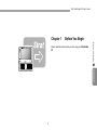
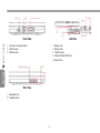
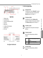
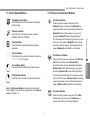
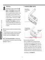
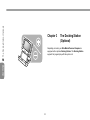
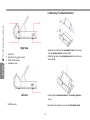
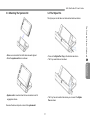
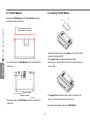
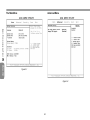
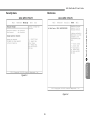
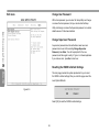
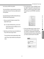
Ultra Mobile PC
User's Guide
Model: U60
First Edition: August 2007
NOTICE
Specifications and information found in this guide are subject to change without notice. Any changes therefore will be incorporated in future
editions. The manufacturer assumes no responsibility for errors or omissions in this document.
TRADEMARKS
•Windows™ is the trademark of Microsoft Corporation.
•Bluetooth® is the trademark owned by its proprietor.
•Other trademarks are properties of their respective owners.
Standards
The following standards are adopted throughout this guide:
•UMPC in boldface (with or without capitalization) refers to the UMPC computer that you have purchased.
•Boldface type is also used to highlight important information in this document.
•Whenever extra caution is called for, the information will be boxed in a dark frame preceded by "Note:" or "Warning:
ENGLISH
Macrovision License of Notice
•This product incorporates copyright protection technology that is protected by U.S. patents and other intellectual property rights. Use of this
copyright protection technology must be authorized by Macrovision, and is intended for home and other limited viewing uses only unless
otherwise authorized by Macrovision. Reverse engineering or disassembly is prohibited.
II
U60 Ultra Mobile PC User’s Guide
CONTENTS
Chapter 3 The Docking Station (Optional)
3.1 Different Views Of The Docking Station................................ 15
3.2 Mounting The Detachable Stand........................................... 16
3.3 Mounting The System Unit.................................................... 17
3.4 The Stylus Pen...................................................................... 17
NOTICE........................................................................................... II
TRADEMARKS................................................................................ II
Standards........................................................................................ II
Macrovision License of Notice......................................................... II
Chapter 4 The BAY Module Connector
4.1 Removing The Flip Stand...................................................... 19
4.2 The BAY Modules.................................................................. 20
4.3 Installing The BAY Module.................................................... 20
4.4 The GPS Module Antenna..................................................... 21
4-5 The TV Tuner Module Antenna............................................. 21
Chapter 1 Before You Begin
1.1 Checking What You Received................................................. 2
1.2 Examining Your Computer....................................................... 2
1.3 The Five System LEDs............................................................ 5
1.4 The Three Control Switches.................................................... 6
1.5 The Six System Buttons.......................................................... 7
1.6 The Four Communication Buttons........................................... 7
1.7 Attention On Media Card Slot.................................................. 8
1.8 Touch Screen Calibration........................................................ 9
1.9 Operating Temperature........................................................... 9
Chapter 5 Using the BIOS Setup Utility
Using the BIOS Setup Utility......................................................... 23
Appendix A Agency Regulatory Notices
A.1 Safety Instructions................................................................. 32
A.2 Agency Notice........................................................................ 35
Chapter 2 Battery
2.1 Battery Pack.......................................................................... 11
2.2 Recharging The Battery Pack................................................ 11
2.3 Questions And Answers........................................................ 11
2.4 Battery Maintenance.............................................................. 12
2.5 Power Consumption.............................................................. 12
2.6 Reducing Power Consumption.............................................. 12
2.7 Removing The Battery Pack.................................................. 13
2.8 Connecting System To AC Adapter....................................... 13
Appendix B Recovery Update Notices
Appendix C Service Center
III
ENGLISH
Chapter 6 Troubleshooting
6.1 Frequently Asked Question................................................... 29
ENGLISH
IV
U60 Ultra Mobile PC User’s Guide
Chapter 1
Before You Begin
Before You Begin
Please read this section before you start using your Ultra Mobile
PC.
ENGLISH
1.2 Examining Your Computer
Your Ultra Mobile PC package should contain the following items:
Before you start using your computer, you need to get acquainted
with its main features and interfaces:
Before You Begin
1.1 Checking What You Received
ENGLISH
Slide the
display panel to
open up keyboard
before you operate.
Panoramic View
•The Ultra Mobile PC.
•AC Adapter.
•AC Power Cord.
•CD Disc (Including Drivers and User's Guide).
•Battery Pack.
•TV Module with Antenna (Option).
•GPS Module with Antenna (Option).
•Docking Station (Option).
•Utility CD.
•Protection Bag.
•Warranty Card.
•Extra stylus pen.
Note: You should keep the original factory carton and packing
materials in case you need to ship the unit back for servicing.
U60 Ultra Mobile PC User’s Guide
1
2
3
4
5
6
7
8
1 Support Foot (also serves to lock and to disassemble the Flip
Stand)
2 Ventilation Holes
3 Speaker
4 Battery Pack
5 Flip Stand
6 Stylus Slot
Web Cam
Two Internal Microphones
LCD Screen
Touch Pad
Five System LEDs
Six System Buttons
Four Communication Buttons
Keyboard
Note: The stylus pen together with the system touch-screen LCD
display provides you a touch-screen operation by emulating the
industry standard mouse right click. You are advised to keep the
stylus pen in the stylus slot when not in use.
ENGLISH
Top View
Before You Begin
Bottom View
Before You Begin
Front View
Left View
1 Connector for Docking Station
2 VGA Connector
3 USB Connector
1
2
3
4
5
ENGLISH
Rear View
1 Kensington Lock
2 Ventilation Holes
Battery Lock
Battery Latch
USB Connector
Media Card Slot (SD/SD-IO)
Battery Pack
U60 Ultra Mobile PC User’s Guide
1.3 The Five System LEDs
The Bluetooth® LED
This LED would be lit when the Bluetooth® is powered
on. For details on how to power on and power off the
Bluetooth, please refer to Chapter 1.6.
Right View
The Wireless LAN LED
Microphone Jack
Power/Hold Switch
Volume (Increase/Decrease) Switch
Stylus Slot
Battery Pack
The SAS (Alt+Ctrl+Del) Switch
Headphone Jack
DC-In Jack
This LED would be lit when the Wireless LAN is
powered on. For details on how to power on and power
off the Wireless LAN, please refer to Chapter 1.6.
The HDD Access LED
This LED would be lit when system is accessing the
HDD drive.
Stereo Jack: Your
headphone jack
should have this type
of connector as shown
here
Below is how the LED would behave in different
situations:
Mono Jack: Your
microphone jack
should have this
type of connector as
shown here.
Two Types of Audio Jack
On
Battery pack is being recharged: fast-charge or
Off
Blinking
pre-charge.
Battery pack is not under recharge.
Battery pack is consuming down to 10% level.
The Power On LED
Below is how the LED would behave in different
situations:
ENGLISH
The Battery Pack LED
Before You Begin
1
2
3
4
5
6
7
8
Off
On
Blinking
1.4 The Three Control Switches
System is powered off, or in Hibernate mode.
System is in full operation.
System is in Standby mode.
The SAS (Alt+Ctrl+Del) Switch
Press this switch to emulate Windows' "Alt", "Ctrl" and
"Del" buttons pressed simultaneously.
Before You Begin
Note: The Five System LEDs are located near the bottom of
display panel. For exact location, please refer to the Top View
diagram in Chapter 1.2.
The Power/Hold Switch
Slide this switch to the right ( ) to emulate standard
power button of a personal computer. The power button
is programmable by user. For details on how to program
the power button, please refer to the Power Options of
Control Panel in Windows™ System.
For more details on Standby and Hibernate, please refer to
Power Options in the Control Panel of your Microsoft Windows™
operating system.
ØFn Keys×
ENGLISH
Slide this switch to the left (HOLD) to temporarily
suspend inputs from the keyboard, touch pad, six
system buttons on the left side of the LCD screen,
and the four communication buttons in between the
left/right keyboard. Manually slide this switch back to the
middle to resume functions of the above input devices.
The purpose of this switch is to prevent mis-triggering
of these input devices while the system unit is idle when
it is powered up. For exact locations of these input
devices, please refer to Top View diagram in Chapter 1.2.
By pressing the Fn keys with other keys, it can simulate all
keyboard functions of a regular desktop keyboard.
[Fn]+[A]: Increase screen brightness.
[Fn]+[Z]: Decrease screen brightness.
[Fn]+[S]: Switch between LCD or external display device.
The Volume Switch
Click this switch to the right (┿) to increase audio volume.
Click this switch to the left (━) to decrease audio volume.
Note: The Three Control Switches is located on the right side
of system unit. For exact location, please refer to the Right View
diagram in Chapter 1.2.
U60 Ultra Mobile PC User’s Guide
1.5 The Six System Buttons
1.6 The Four Communication Buttons
The Mobility Center Button
Press this button to enter into the menu of optimized
mobility setting.
The Bluetooth Button
The Zoom-In Button
Press this button to change the screen resolution
(800x480, 1024x600, 1280x768) .
The Enter Button
Press this button to start the hand writing software
application.
The Scroll Button
Press this button to emulate the functions of these four
"f", "g", "h", and "i" keycaps.
The Wireless LAN Button
The Left Mouse Button
Press this button to emulate the left mouse function.
The Right Mouse Button
Press this button to emulate the right mouse function.
Note: The Six System Buttons are located on the left side of
the LCD display. For exact location, please refer to the Top View
diagram in Chapter 1.2.
The Web Cam Button
Press this button to power on and power off the Web
Cam module. After powering on the Web Cam, you
need to activate its function through Windows™.
ENGLISH
Press this button to power on and power off the Wireless
LAN module. Powering on the Wireless LAN by
pressing this button does not automatically activate the
Wireless LAN function. After powering on, you need to
activate the Wireless LAN function through Windows™.
The main purpose of this button is to provide you a quick
way to turn off the power of Wireless LAN when entering
venues like airplanes, airports, and hospitals where the
usage of Wireless LAN is prohibited or not advisable.
Before You Begin
Press this button to power on and power off the
Bluetooth® module. Powering on the Bluetooth® by
pressing this button does not automatically activate the
Bluetooth® function. After powering on, you need to
activate the Bluetooth® function through Windows™.
The main purpose of this button is to provide you a quick
way to turn off the power of Bluetooth® when entering
venues like airplanes, airports, and hospitals where the
usage of Bluetooth® is prohibited or not advisable.
1.7 Attention On Media Card Slot
Before You Begin
The BAY Button
Press this button to power on and power off the GPS
Module or TV Tuner Module. Powering on the GPS
Module or TV Tuner Module by pressing this button
does not automatically activate the respective functions.
After powering on, you need to activate the function
through Windows™. This button would work only when
the system is powered on, and either one of the GPS
or TV Tuner Module is connected into the system unit.
Note: GPS and TV Tuner Modules are optional and
need to be purchased separately. For details on how to
connect these modules to the system unit, please refer
to Chapter 4.
Media Slot Door is
now inserted into the
system unit.
The Media Slot Door is
now taken out from the
system unit.
ENGLISH
Note: The proper way to activate the above devices and modules
is as below:
1) Press the above buttons to power on the devices, and modules.
2) Activate the respective application programs in Windows™.
The effective range of the system Bluetooth® is 10 meters.
Note: The Four Communication Buttons are located between
the left/right keyboards. For exact location, please refer to the Top
View diagram in Chapter 1.2.
Arrow on topside
of Media Slot
Door.
Please observe below safety measures:
•When no card (SD/SD-IO cards) is inserted into the media
slot, make sure this slot is covered by the "media slot door" as
supplied together with this Ultra Mobile PC. The purpose of this
"media slot door" is to prevent foreign matters from entering into
the system unit through this slot, when no card is inserted. When
inserting this "media slot door", please make sure the arrow is on
the topside as shown above. Inserting this door upside down may
cause damage to your Ultra Mobile PC.
U60 Ultra Mobile PC User’s Guide
1.8 Touch Screen Calibration
1.9 Operating Temperature
The stylus pen together with the system touch-screen LCD display
provides you a touch-screen operation by emulating the industry
standard mouse right click. Below are the two conditions that you
need to calibrate your touch-screen.
Operating Temperature:
Before You Begin
•The first time Windows is installed and boot up. The active cursor
is shifted; not exactly the same position where the stylus pen tip is
tapped.
•Periodically when you find the active cursor is shifted away from
the screen position where the stylus pen tip is tapped.
10°C to 35°C.
To calibrate the touch-screen, go into Tablet PC Setting of
Control Panel of Windows™ XP. In the Tablet PC Setting
screen, select General and then Calibrate. Then follow instruction
to complete calibration.
ENGLISH
Note: You need to set screen display resolution to 800x600 before
proceeding with the calibration.
Battery
Chapter 2
ENGLISH
10
Battery
U60 Ultra Mobile PC User’s Guide
2.1 Battery Pack
2.3 Questions And Answers
Your Ultra Mobile PC is equipped with a high-energy rechargeable
Lithium Ion (Li-Ion) battery pack. Battery life will vary depending
on the product configuration, product model, applications loaded
on the product, power management settings of the product, and
the product features used by the customer. As with all batteries,
the maximum capacity of this battery will decrease with time and
usage.
I can feel a mild heat next to the battery pack. Is it normal?
The battery will generate heat during recharging and
discharging. There is a protection circuit inside the Ultra
Mobile PC to prevent overheating. User needs not to worry.
The battery is heat sensitive and can only be charged to its
maximum if the battery and its environmental temperature
remain within 15-25°C (59-77°F). The more the temperature
deviates from this range during recharging, the less chance
there is for the battery to be fully charged. In order to
recharge the pack to its full capacity, users are requested
to cool down the unit by unplugging the AC Adapter. Wait
until it is cooled down. Then plug in the AC Adapter to start
recharging again.
I did not use my spare battery for a few days. Even though
it was fully recharged, there wasn’t as much power left as a
newly charged one. Why?
The batteries will self-discharge (1% per day for Li-Ion)
when they are not being recharged. To make sure a battery
pack is fully charged, recharge before use. Always keep the
battery inside the Ultra Mobile PC and have the AC adapter
connected whenever possible.
2.2 Recharging The Battery Pack
Your Ultra Mobile PC supports both on-line and off-line recharge.
Follow the procedure below to recharge battery:
•Make sure the battery pack is installed in the Ultra Mobile PC.
•Connect the AC adapter to the Ultra Mobile PC and to an
electrical outlet.
When a battery pack is being recharged, its battery LED (located
at the bottom of LCD display) would be lit. For details on the LEDs,
please refer to Chapter 1.3. When the Ultra Mobile PC is OFF, a
depleted Li-Ion battery will take three hours to recharge.
11
ENGLISH
My battery operation time is not as long as it should be.
Why?
Battery
Battery
I did not use my spare battery for months. I have problem in
recharging it.
If you happen to leave your battery pack to go through an
extended period of self-discharge, say more than three
months, the battery voltage level will become too low and
needs to be Pre-Charged (to bring the battery voltage level
high enough) before it automatically (for Li-Ion only) resumes
its normal Fast Charge. Pre-Charge may take 30 minutes.
Fast Charge usually takes 2~3 hours.
2.5 Power Consumption
The Windows™ operating system has incorporated the latest
state-of-the-art ACPI (Advanced Configuration Power Interface)
power management methodology. In order to fully utilize the
power of your battery packs, it would be a good idea for you to
spend sometime to acquire a basic understanding of the power
management concept from your operating system.
In Windows™ Operating Systems, you can go through Power
Options of the Control Panel according to the version of
Windows™ Operating System the Ultra Mobile PC applies. We
shall not describe them in details.
2.4 Battery Maintenance
To maintain the battery pack's maximum capacity, you should
occasionally let the Ultra Mobile PC deplete its battery power
completely before recharging.
2.6 Reducing Power Consumption
ENGLISH
Although your Ultra Mobile PC (together with the operating
system) is capable of power conservation, there are measures you
can take to reduce the power consumption:
• Use the AC power whenever possible.
• Try to use the HDD drive to read and write files, instead of
using the external USB FDD.
• Disable unused devices, such as Web Cam, WLAN, Bluetooth®,
and etc.
• Decrease LCD panel brightness through Windows.
To carry out a complete depletion of the battery, disconnect the
AC adapter and let your Ultra Mobile PC consume the remaining
battery power. To speed up the depletion, use the HDD as much as
possible. When the battery is empty, wait for the Ultra Mobile PC
to cool down (especially the battery). The temperature should be
within 15-25°C (59-77°F). Then insert the AC adapter to recharge
the battery.
Note: Whenever system is powered on or powered off, make sure
the battery pack is installed in the battery pack compartment.
12
U60 Ultra Mobile PC User’s Guide
2.7 Removing The Battery Pack
2.8 Connecting System To AC Adapter
This battery pack can easily be removed and replaced. Make sure
that the computer is properly shutdown before changing the battery
pack. If you would like to change the battery pack while power is
on, make sure this battery pack is not the only electrical source to
the system unit. Follow the steps below to remove the battery pack.
Battery
•Make sure the system is properly shutdown.
•Flip the system upside down as shown.
•Push the battery lock to the unlock position as shown by #1.
•Push the battery latch to the unlock position as shown by #2.
•Remove the battery pack as shown by #3.
To insert the battery pack, reverse the steps above.
13
ENGLISH
•Connect AC adapter to system unit as shown by #1.
•Connect AC power cord to AC adapter as shown by #2.
•Connect other end of power cord to an electrical outlet as shown
by #3.
The Docking Station (Optional)
Chapter 3 The Docking Station
(Optional)
Depending on model, your Ultra Mobile Personal Computer is
equipped with an optional Docking Station. This Docking Station
supports hot plug-and-play with the system unit.
ENGLISH
14
U60 Ultra Mobile PC User’s Guide
3.1 Different Views Of The Docking Station
1 Power Button
2 Detachable Stand
ENGLISH
Panoramic View
The Docking Station (Optional)
Front View
1 Power Button
2 Connector to System Unit
3 Detachable Stand
Rear View
Note: This Power Button has the same function as the Power
Switch as described in Chapter 1.4. For details, please refer to
Chapter 1.4.
1
2
3
4
The Detachable Stand is shipped not mounted to the main body of
the Docking Station as shown above. For details on how to mount
this Detachable Stand, please refer to Chapter 3.2.
15
USB Connectors
RJ45 LAN Connector
DC-In Jack
VGA Connector
The Docking Station (Optional)
3.2 Mounting The Detachable Stand
Right View
ENGLISH
1
2
3
4
•Align and lock the tenon from detachable stand to the mortise
from the docking station as shown by #1.
•Slide the right side of the detachable stand in the direction as
shown by #2.
Stylus Pen
Stylus Pen Tray (push to eject)
IEEE 1394 Connector
Headphone Jack
Left View
•Gently press the detachable stand to the docking station as
shown.
1 USB Connector
Reverse the above steps to un-mount the detachable stand.
16
U60 Ultra Mobile PC User’s Guide
3.3 Mounting The System Unit
3.4 The Stylus Pen
The stylus pen can be taken out and erected as shown below:
•Press on the Stylus Pen Tray in the direction as shown.
•The Tray would slide out as shown.
The Docking Station (Optional)
•Make sure connectors from both sides are well aligned.
•Slide the system unit down as shown.
ENGLISH
•System unit is mounted when the two connectors are full
engaged as shown.
•The Tray has an insertion hole where you can erect the Stylus
Pan as shown.
Reverse the above steps to un-mount the system unit.
17
The BAY Module Connector
Chapter 4
ENGLISH
18
The BAY Module
Connector
U60 Ultra Mobile PC User’s Guide
4.1 Removing The Flip Stand
•Gently flip the flip stand to an almost erect angle as shown.
The BAY Module Connector
This Ultra Mobile PC has a BAY Module Connector whereby by
you can either choose to connect it to a GPS (Global Positioning
System) Module, or a TV Tuner Module. Both the GPS Module
and TV Tuner Module are optional and need to be purchased
separately. The BAY Module Connector is underneath the flip
stand. Diagram below shows the bottom view of the system unit
with the flip stand removed.
ENGLISH
The BAY Module Connector
The rest of this chapter describes how the flip stand is removed
and how the GPS Module and TV Tuner Module are installed to
the system unit.
•Press and slide the support foot in the direction as shown by #1.
•Remove the flip stand as shown by #2.
Reverse the steps above to put back the flip stand.
19
4.2 The BAY Modules
4.3 Installing The BAY Module
The BAY Module Connector
Externally, the GPS Module and TV Tuner Module looked very
much the same as shown below.
The two tenons are used for
locking module to system unit.
ENGLISH
•Align and lock the tenon from the module to the mortise from the
system unit as shown by #1.
•Slide support foot in the direction as shown by #2.
•Gently press on the back of the connector to connect module as
shown by #3.
•The external side of the BAY Module when it is installed to the
system unit.
Connect to system
•The support foot would slide back by itself in the direction as
shown. The module is locked to the system unit.
Connect to antenna
•The internal side of the BAY Module when it is installed to the
system unit.
Reverse the above steps to remove the BAY Module.
20
U60 Ultra Mobile PC User’s Guide
4.4 The GPS Module Antenna
4-5 The TV Tuner Module Antenna
The GPS Module has a built-in internal antenna.
TV Tuner Module is without a built-in internal antenna. Therefore,
it is necessary to use its proprietary external antenna as shown
below.
The BAY Module Connector
21
ENGLISH
Note:
1.Please install the TV driver (Driver is on your U60 Utility CD)
2.Please install the TV application software (Application CD is on your accessory package)
3.Connect external antenna to the TV Tuner Module.
Note: Before you using GPS module:
1.Please install the GPS driver (Driver is on your U60 Utility CD)
2.Please set the GPS Module device communication port to COM4 and baud rate to 115200.
Using the BIOS Setup Utility
Chapter 5
ENGLISH
22
Using the BIOS Setup
Utility
U60 Ultra Mobile PC User’s Guide
Using the BIOS Setup Utility
Navigating and Entering Information in BIOS
Your UMPC has a BIOS setup utility which allows you to configure
important system settings, including settings for various optional
functions of the computer. This chapter explains how to use the
BIOS setup utility.
Use the following keys to move between fields and to enter
information:
Select Screen
BIOS Setup Menu
The BIOS setup Utility allows you to configure your computer's
basic settings. When you turn your computer on, the system reads
this information to initialize the hardware so that it can operate
correctly. Use the BIOS setup utility to change your computer's
start-up configuration. For example, you can change the security
and power management routines of your system.
You can only enter the BIOS setup utility as the computer is
booting, that is between the time you turn on the computer and
before the Windows interface appears. If your computer is already
on, shut down your computer completely (power off) and restart it
and then press the Fn+F2 key to enter the setup utility.
Change Option
Select Field
F1
General Help
F10
Save and Exit
ESC
Press Esc to exit any section. If you
wish to exit the BIOS utility without
saving changes, go to the main menu,
then press Esc.
Users are allowed to enter new values to replace the default
settings in certain fields, and the rest fields are specified by system
default parameters and cannot be modified by users. Reverse
the attribute of the main options and press the Enter key to enter
into the submenu. Press the Esc key to return to the previous
configuration page.
23
ENGLISH
Starting the BIOS Setup Utility
+Tab
Using the BIOS Setup Utility
Push the up and down arrow keys to
move among selections, then press
Enter to make a selection.
Advanced Menu
Using the BIOS Setup Utility
The Main Menu
ENGLISH
Figure 5-1
Figure 5-2
24
U60 Ultra Mobile PC User’s Guide
Security menu
Boot menu
Using the BIOS Setup Utility
ENGLISH
Figure 5-3
Figure 5-4
25
Exit menu
Change User Password
Using the BIOS Setup Utility
With a User password, you can enter the Setup Utility and change
or remove the User password, but you cannot enter the Setup
Utility and change or remove the Supervisor password, nor enable
diskette access if it has been disabled.
Change Supervisor Password
A supervisor password must be set before a lower-level user
password can be set. After selecting Change Supervisor
Password, press Enter. You will be prompted for the new
password, and then again to verify it. Type in 6 or fewer keystrokes.
If you make an error, press Esc to start over.
Resetting the CMOS to Default Settings
ENGLISH
The main page provides the system parameters for you to reset
the CMOS to default settings. After you enter this page, select the
Load Optimal Defaults:
Figure 5-5
Select [OK] to reset the CMOS to default settings.
26
U60 Ultra Mobile PC User’s Guide
Exiting and Saving
Select this option to save changes
to the field values, and restart the
computer using the new values.
(Pressing F10 from any of the menu
screens also allows you to save
settings and exit.)
Exit Without
Saving
Select this option to discard any
changes you have made to the field
values, and restart the computer using
the old values.
Using the BIOS Setup Utility
Save Settings
and Exit
ENGLISH
27
Troubleshooting
Chapter 6
Troubleshooting
In this chapter, we will list some frequently encountered technical
problems and tell you how to resolve them.
6
ENGLISH
ffield Foundation
28
U60 Ultra Mobile PC User’s Guide
6.1 Frequently Asked Question
My computer switches to hibernation mode much too quickly,
and I have to constantly hit a key or move the mouse to bring
back the screen. What can I do?
I've heard that cleaning and rearranging files on the hard
drive will improve program's launch speed, how do I do this?
Good disk maintenances can improve program launch
speed. This normally includes deleting unnecessary files,
and defragmenting hard disk so that files can be more
efficiently grouped. Windows contains maintenance utilities
for these tasks; run Disk Cleanup to remove unnecessary
files, and Disk Defragmenter to defragment fragmented file
blocks. For more information about these utilities, please
refer to your Windows documentation.
The dial tone volume of the internal fax/modem is too low.
How can I increase its volume?
Go to Start/Control Panel/Sounds, Speech, and Audio
Devices, under Device volume, adjust your speaker volume
by controlling the volume bar.
29
You will need to use a self-amplifying microphone.
There are echoes coming from my speakers. What can I do?
Double click on the Speaker icon on the task bar. Then,
under Microphone Balance, check the Mute box.
Because of a software problem, I was unable to shut the
computer down from Windows, I pressed the power button to
power off the computer, but it didn't work. How can I force a
power off?
Make sure you press the power button for at least 4 seconds.
Normally, this will force the computer to shut off.
Why can't I charge the battery of my portable computer after
it was out of use for some time?
After your portable computer has not been used for a long
time (say: more than one month), the battery will enter into
low voltage protection mode. Under this circumstance,
restoring to normal voltage will require the battery to be
slowly charged for several hours. Once the battery has been
fully charged, your will resume to normal operation.
My computer says: "CMOS Battery Low", what should I do?
6
ENGLISH
What kind of external microphone can I use with my UMPC
computer?
Troubleshooting
This is part of Windows Power Management. Access
Power Management by clicking on Start / Control Panel /
Performance and Maintenance / Power Options, and change
the time next to the "Turn off monitor" option to the time you
want. You have the choice of either adjusting time for the
power supply or for the battery.
Troubleshooting
6
If your computer is without power (i.e. unplug the computer
power source from the power outlet and remove the battery
pack from it) for over 45 days, you would lose the information
stored in CMOS.
Please follow the steps below to reconfigure your CMOS
settings:
1. Press F2 to enter into the BIOS setup utility.
2. Select "Load Optional Defaults?". When you see the
following prompt, choose <OK> and then press <Enter>.
3. Select "Save Changes and Exit", select <OK> and press
<Enter> to restart your computer.
ENGLISH
How to unplug or eject devices?
1. In the notification area next to your task bar, double-click
the Safe Removal icon. Safe Removal displays a list of
Plug and Play devices that support safe removal and that
are currently attached to the system.
Caution
•Unplugging or ejecting a device that supports safe
removal without first using the Safe Removal application
to warn the system can cause data to be lost or your
system to become unstable. For example, if a device is
unplugged during a data transfer, data loss is likely. If you
use Safe Removal, however, you can warn the system
before you unplug or eject a device, preventing possible
loss of data.
Note
•For removable storage devices that can safely be
removed while the system is on, the system disables
write caching by default. It does this so the devices can
be removed without loss of data. When write caching
is disabled, however, the system will likely experience
slower performance, so be sure to enable write caching
when you have finished removing the device.
If you do not see the Safe Removal icon, your device
does not supports safe removal, and you cannot unplug
or eject your device using Safe Removal.
2. In Safely Remove Hardware, in the list of devices, select
the device that you want to unplug or eject, and then click
Stop. This tells the system that you will be unplugging or
ejecting the device.
3. In Stop a Hardware device, click OK.
A notification appears stating that it is now safe to unplug
or eject the device.
30
U60 Ultra Mobile PC User’s Guide
Agency Regulatory Notices
Appendix A Agency Regulatory
Notices
ENGLISH
31
A.1Safety Instructions
CAUTION: Verify the voltage of the power source before
connecting the unit to any power outlet.
Agency Regulatory Notices
CAUTION: Please read these safety instructions
carefully.
WARNING: DO NOT step on or place anything over the
power cord.
CAUTION: Please keep this User's Manual for future
reference.
CAUTION: All cautions and warnings on the equipment
should be noted.
CAUTION: Please disconnect this equipment from AC
outlet before cleaning. DO NOT use liquid or sprayed
detergent for cleaning. Use a clean moistened cloth.
WARNING: If the equipment is not used for a long period
of time, disconnect the equipment from the power source
to avoid damage from power spikes.
CAUTION: The wall socket used should be positioned
near the equipment and should be easily accessible.
ENGLISH
WARNING: NEVER pour any liquid into any openings; a
fire or electrical shock is possible.
CAUTION: Please keep this equipment free from
humidity.
WARNING: For safety reasons, other than predesignated ports, doors, and the equipment should be
opened only through qualified service personnel.
CAUTION: Place the equipment on a reliable surface at
all times. A drop or fall can cause severe damage.
WARNING: The openings of the enclosure are for air
ventilation and are meant to protect the equipment from
overheating. DO NOT COVER THE VENTILATION
OPENINGS.
32
U60 Ultra Mobile PC User’s Guide
CAUTION: Use caution when installing or modifying
modem/telephone lines.
WARNING: Avoid using a modem/telephone (other than
a cordless type) during an electrical storm. There may be
a remote risk of electric shock from lightning.
WARNING: This computer contains an internal lithium
battery-powered real-time circuit. There is a risk of
explosion and injury if the battery is incorrectly replaced
or handled. Do not attempt to recharge, disassembled,
immerse in water, or dispose of it in fire. Replacement
should be done through your UMPC dealer.
CAUTION: DO NOT LEAVE THE EQUIPMENT IN
TEMPERATURES BELOW -20°C°(-4°F) OR ABOVE
60°C (140°F). IT MAY CAUSE DAMAGE TO THE
EQUIPMENT.
WARNING: Never install modem/telephone wiring during
a lightning storm.
WARNING: Never install modem/telephone jacks in wet
locations unless the jack is specially designed for wet
locations.
WARNING: Never touch un-insulated modem/telephone
wires or terminals unless the modem/telephone line has
been disconnected at the network interface.
33
ENGLISH
WARNING: Danger of explosion if battery is incorrectly
replaced. Replace only with the same or equivalent type
recommended by the manufacturer. Dispose of used
batteries according to the manufacturer's instructions.
Explosionsgefahr bei unsachgemäßen Austausch der
Batterie. Ersatz nur durch denselben oder einem vom
Hersteller empfohlenem ähnlichen Typ. Entsorgung
gebrauchter Batterien nach Angaben des Herstellers.
Agency Regulatory Notices
CAUTION: If one of the following situations should arise,
the equipment should be checked by an authorized
technician:
a.The power cord or plug is damaged.
b.Liquid has penetrated into the equipment.
c.The equipment has been exposed to excessive
moisture.
d.The equipment does not work well, or you fail to get it
to work according to user's manual.
e.The equipment has been dropped or damaged.
f. The equipment has obvious signs of breakage.
Agency Regulatory Notices
WARNING: Your UMPC contains a Ni-MH or LiIon battery pack. There is a risk of fire and chemical
burn if the battery pack is handled improperly. Do not
disassemble, crush, puncture, short external contact,
dispose of in water or fire, or expose it to temperature
higher than 60°C.
WARNING: Don't expose your UMPC to excessive heat
or coldness (frost). Don't drop, spill fluids or open the
exterior of the case. This can damage the UMPC and
void the warranty.
WARNING: This device is equipped with the precisely
designed storage device. Do not have the operation
under the condition with vibration.
WARNING: Handle the battery pack very carefully. Avoid
touching the metal leads on the connector of the battery
case.
WARNING: Please pay attention for below matters at
mounting design of touch panel of LCD module.
1.Do not put a heavy force along the edge of active area
2.Do not put a heavy shock or stress on the touch panel
and film surface.
3. Do not put heavy goods on the touch panel.
CAUTION: Use only approved AC Adapter with your
UMPC. Using the wrong type of AC Adapter may cause
serious damage to your UMPC.
ENGLISH
CAUTION: The AC Adapter can accept a line voltage
ranging from 100V to 240V and is compatible with most
international power sources. If you are unsure whether
your power source is compatible, please contact the local
dealer for assistance.
CAUTION: For Continued Protection Against Risk of
Fire, Replace Only with same Type and Rating of Fuse.
CAUTION: If the computer is not sold to German area,
please use only the local recognized power supply cords
that are recommended by the manufacturer.
34
U60 Ultra Mobile PC User’s Guide
A.2Agency Notice
Cables
Connections to this device must be made with shielded cables with
metallic RFI/EMI connector hoods to maintain compliance with
FCC Rules and Regulations.
Federal Communications Commission Notice
FCC RF Radiation Exposure Statement
•This transmitter must not be co-located or operating in conjunction
with any other antenna or transmitter.
However, there is no guarantee that interference will not occur
in a particular installation. If this equipment does cause harmful
interference to radio or television reception, which can be
determined by turning the equipment off and on, the user is
encouraged to try to correct the interference by one or more of the
following measures:
•Reorient or relocate the receiving antenna.
•Increase the separation between the equipment and receiver.
•Connect the equipment into an outlet on a circuit different from
that to which the receiver is connected.
•Consult the dealer or an experienced radio or television technician
for help.
The following safety precautions should be observed:
•Do not touch or move antenna while the unit is transmitting or
receiving.
•Do not hold any component containing the radio such that the
antenna is very close or touching any exposed parts of the body,
especially the face or eyes, while transmitting.
•Do not operate the radio or attempt to transmit data unless the
antenna is connected; if not, the radio may be damaged.
Use in specific environments:
•The use of wireless devices in hazardous locations is limited
by the constraints posed by the safety directors of such
Modifications
The FCC requires the user to be notified that any changes or
modifications made to this device that are not expressly approved
by the manufacturer responsible for compliance may void the
user's authority to operate the equipment.
35
ENGLISH
USA and Canada Safety Requirements And Notices
The FCC with its action in ET Docket 93-62 has adopted a
safety standard for human exposure to radio frequency (RF)
electromagnetic energy emitted by FCC certified equipment.
The Intel PRO/Wireless LAN MiniPCI Adapter products meet the
Human Exposure limits found in OET Bulletin 65, 2001, and ANSI/
IEEE C95.1, 1992. Proper operation of this radio according to the
instructions found in this manual will result in exposure substantially
below the FCC's recommended limits.
Agency Regulatory Notices
This equipment has been tested and found to comply with the limits
for a Class B digital device, pursuant to part 15 of the FCC Rules.
These limits are designed to provide reasonable protection against
harmful interference in a residential installation. This equipment
generates, uses and can radiate radio frequency energy and, if not
installed and used in accordance with the instructions, may cause
harmful interference to radio communications.
environments.
•The use of wireless devices on airplanes is governed by the
Federal Aviation Administration (FAA).
•The use of wireless devices in hospitals is restricted to the limits
set forth by each hospital.
maximum shielding. Equipment (or its transmit antenna) that is
installed outdoors is subject to licensing.”
Agency Regulatory Notices
Explosive Device Proximity Warning
Warning: Do not operate a portable transmitter (such as a wireless
network device) near unshielded blasting caps or in an explosive
environment unless the device has been modified to be qualified
for such use.
“Pour empêcher que cet appareil cause du brouillage au service
faisant l’objet d’une licence, il doit être utilizé à l’intérieur et devrait
être placé loin des fenêtres afin de fournir un écran de blindage
maximal. Si le matériel (ou son antenne d’émission) est installé à l’
extérieur, il doit faire l’objet d’une licence.”
ENGLISH
Canadian Notice
Cet appareil numérique de la classe B est conforme à la norme
NMB-003, No. 2, et CNR-210, No. 4 (Dec. 2000).
Use On Aircraft Caution
Caution: Regulations of the FCC and FAA prohibit airborne
operation of radio-frequency wireless devices because their signals
could interfere with critical aircraft instruments.
European Union
Notice
Product with the CE Marking comply with the EMC Directive
(89/336/EEC) and the Low Voltage Directive (73/23/EEC) issued
by the Commission of the European Community and if this product
has telecommunication functionality, the R&TTE Directive (1999/5/
EC).
This Class B digital apparatus meets all requirements of the
Canadian Interference-Causing Equipment Regulations.
Compliance with these directives implies conformity to the following
European Norms (in parentheses are the equivalent international
standards and regulations):
•EN55022 (CISPR 22) — Electromagnetic Interference
•EN55024 (IEC61000-4-2,3,4,5,6,8,11) — Electromagnetic
Immunity
•EN61000-3-2 — (IEC61000-3-2)-Power Line Harmonics
•EN61000-3-3 — (IEC61000-3-3)-Power Line Flicker
•EN60950 (IEC60950) — Product Safety
Avis Canadien
Cet appareil numerque de la classe B respecte toutes les
exigences du Reglement sur le materiel brouilleur du Canada.
Canada Radio Frequency Interference Requirements
This Class B digital apparatus complies with Canadian ICES-003,
Issue 2, and RSS-210, Issue 4 (Dec. 2000).
"To prevent radio interference to the licensed service, this device is
intended to be operated indoors and away from windows to provide
36
U60 Ultra Mobile PC User’s Guide
For devices with built-in wireless equipment, the following additional
standards apply:
•ETSI301489-17: General Emissions for Radio Equipment
•EN60950: Safety
•ETSI300328-2: Technical Requirements for Radio Equipment
24
25
26
27
Dordogne
Doubs
Drôme
Eure
63
64
65
66
32
35
Gers
Ille et Vilaine
67
68
CE Caution: Due to the fact that the frequencies used by
The wireless LAN device cannot currently be used in any
departments of mainland France other than those listed above.
Frequency Ranges (MHz)
2400 – 2446.5
2446.5 – 2483.5
Japanese Notice
36
37
39
41
42
45
50
54
55
57
58
59
60
61
Indre
Indre et Loire
Jura
Loir et Cher
Loire
Loiret
Manche
Meurthe et Moselle
Meuse
Moselle
Nièvre
Nord
Oise
Orne
69
70
71
72
75
77
78
79
82
84
86
88
89
90
Rhône
Haute Saône
Saône et Loire
Sarthe
Paris
Seine et Marne
Yvelines
Deux Sèvres
Tarn et Garonne
Vaucluse
Vienne
Vosges
Yonne
Territoire de Belfort
37
Indoors
10 mW
100 mW
Outdoors
Not permitted
100 mW on private property
with Ministry of Defense
approval
ENGLISH
Ain
Aisne
Allier
Hautes Alpes
Ardennes
Ariège
Aube
Aude
Aveyron
Charente
Corrèze
Corse Sud
Haute Corse
Côte d’Or
Essonne
Hauts de Seine
Seine St Denis
Val de Marne
Maximum allowable EIRP 802.11b wireless LAN cards in the
mainland departments of France not shown in the table above
are as follows: (See the ART website at www.art-telecom.fr for
information on the French overseas territories.)
The wireless LAN device can currently be used indoors only in the
following departments of mainland France.
01
02
03
05
08
09
10
11
12
16
19
2A
2B
21
91
92
93
94
Agency Regulatory Notices
802.11b/802.11g wireless LAN devices may not yet be harmonized
in all countries, 802.11b/802.11g products are designed for use
only in specific countries or regions, and are not allowed to be
operated in countries or regions other than those of designated
use. As a user of these products, you are responsible for ensuring
that the products are used only in the countries or regions for
which they were intended and for verifying that they are configured
with the correct selection of frequency and channel for the country
or region of use. And deviation from permissible settings and
restrictions in the country or region of use could be an infringement
of local law and may be punished as such.
Puy du Dôme
Pyrénées Atlantique
Haute Pyrénées
Pyrénées
Orientales
Bas Rhin
Haut Rhin
Agency Regulatory Notices
DGT Statement
operation of your equipment. If they do, you will be notified in
advance to give you an opportunity to maintain uninterrupted
telephone service.
根據 交通部低功率管理辦法 規定:
第十四條 經型式認證合格之低功率射頻電機,非經許可,公
司、商號或使用者均不得擅自變更頻率、加大功率或
變更原設計之特性及功能。
第十七條 低功率射頻電機之使用不得影響飛航安全及干擾合法
通信,經發現有干擾現象時,應立即停用,並改善至
無干擾時方得繼續使用。
第二十條 輸入、製造低功率射頻電機之公司、商號或使用者違
反本辦法規定,擅自使用或變更無線電頻率、電功率
者,除依電信法規定處罰外,電信總局並得撤銷其型
式認證或型式認證標籤。
The FCC prohibits this equipment to be connected to party lines or
coin-telephone service.
In the event that this equipment should fail to operate properly,
disconnect the equipment from the phone line to determine if
it is causing the problem. If the problem is with the equipment,
discontinue use and contact your dealer or vendor.
The FCC also requires the transmitter of a FAX transmission be
properly identified (per FCC Rules Part 68, Sec 68.381 (C) (3)).
U.S. Regulations Governing the Use of Modems
Japanese Modem Notice
ENGLISH
This equipment complies with Part 68 of the FCC Rules. On this
equipment is a label that contains, among other information,
the FCC registration number and Ringer Equivalence Number
(REN) for this equipment. You must, upon request, provide this
information to your telephone company.
U.K. Modem Compliance Information
If your telephone equipment harms the telephone network, the
Telephone Company may discontinue your service temporarily.
If possible, they will notify in advance. But, if advance notice is
not practical, you will be notified as soon as possible. You will be
informed of your right to file a compliant with the FCC.
This modem is approved by the secretary of state at the
Department of Trade and Industry for connection to a single
exchange line of the public switched telephone network run by
certain licensed public telecommunication operators or system
connected there to (Direct exchange lines only, not shared service
or 1-1 carrier systems).
Your telephone company may make changes in its facilities,
equipment, operations, or procedures that could affect proper
38
U60 Ultra Mobile PC User’s Guide
This modem is also suitable for connection to Private Automatic
Branch Exchange (PABX), which return secondary proceeding
indication.
Unless otherwise marked, a telephone is assumed to have a REN
of 1.
This modem is suitable for use only on telephone lines proved with
Loop Disconnect or Multi-Frequency Dialing Facilities.
There is no guarantee of correct working in all circumstances. Any
difficulties should be referred to your supplier.
Some network operators require that intended users of their
network request permission to connect and for the installation of an
appropriate socket.
The Ringer Equivalence Number (REN) of this modem is 1.
REN is guide to the maximum number of apparatus that can
simultaneously be connected to one telephone line. The REN value
of each apparatus is added together, and should not exceed 4.
39
ENGLISH
Users of this modem are advised that the approval is for connection
to the PSTN via the telephone line interface supplied with it.
Connection of a modem to the PSTN by any other means will
invalidate the approval.
Agency Regulatory Notices
This modem is only approved for use of the following facilities:
•Storage of telephone numbers for retrieval by a predator mined
code.
•Initial proceed indication detection.
•Automatic calling / automatic answering.
•Tone detection.
•Loud-speaking facility.
This modem is not approved for connection to U.K./private speechband services. This modem does not support an automatic redial function. Any other usage will invalidate the approval of your
modem, if as a result, it then ceases to confirm to the standards
against which approval was granted. The approval of this modem is
invalidated if the apparatus is subject to modification in any material
way not authorized by the BABT or if it is used with, or connected
to external software that have not been formally accepted by
BABT.
If this modem is to be used with a PBX which has extension
wiring owned by BT, connection of the modem the PBX can only
be carried out by BT; or by the authorized maintainer of the PBX
unless the authorized maintainer has been given 14 days written
notice that the connection is to be made by another person; and
that period of notification has expired.
Recovery Update Notices
Appendix B Recovery Update
Notices
ENGLISH
40
U60 Ultra Mobile PC User’s Guide
How to restore your UMPC to factory defaults
3. There are three options on the menu: "RESTORE" (to restore
data), "ABOUT" (to display XR2 Lite related information) and
"REBOOT" (to cancel the recovery and restart the computer).
We recommend you to select "RESTORE" to restore factory
defaults.
Time to restore: When your computer is infected by virus or there is
any other reason that you want to restore your operation system to
the factory defaults.
1. Start up your computer first. Restart your computer if it has
already booted into system.
Note: If your system OS is Microsoft Vista, you have to insert
the driver DVD and boot from the ODD device to run the
Express 2 Recovery function.
2. Right after you see the startup screen (such as trademark, logo
or text), the DOS screen will appear. Press F9.
* F9 is a typical hotkey to restore professional settings. Please
consult with your computer manufacture if your hotkey doesn't
function.
41
ENGLISH
4. Then the prompt "Restore Image?" will appear on the menu.
We recommend you to select "YES" to restore an image
file.* "Image file" is a compressed file that compresses all the
Windows operation system data. Recovery an image file allows
you to restore your operation system to factory defaults.
Recovery Update Notices
Execute Xpress Recovery2 Lite (XR2 Lite) Professional Recovery
Utility.Please take the following procedures:
Recovery Update Notices
5. After all the selections have been made, the screen shows
"RESTORE NOW…", indicating your computer is now
recovering the operation system data. When the recovery is
complete, the computer will automatically restart and restore to
factory defaults.
ENGLISH
42
U60 Ultra Mobile PC User’s Guide
Appendix C Service Center
Service Center
This appendix will list our global service centers for your U60 Ultra
Mobile PC.
C
ENGLISH
43
Taiwan ( Headquarters ) GIGA-BYTE TECHNOLOGY CO., LTD.
Beijing
TEL: +86-10-62102838
FAX: +86-10-62102848
Address: No.6, Bau Chiang Road, Hsin-Tien, Taipei 231, Taiwan
TEL: +886 (2) 8912-4888
FAX: +886 (2) 8912-4004
Chengdu
TEL: +86-28-85236930
FAX: +86-28-85256822
Service Center
How to submit a question?
Technical
Issues about using GIGABYTE products.
Non-technical
Sales and marketing issues
C
Wuhan
TEL: +86-27-87851061
FAX: +86-27-87851330
WEB Address(English): http://www.gigabyte.com.tw/
WEB Address(Chinese): http://www.gigabyte.tw/
U.S.A.
Xian
TEL: +86-29-85531943
FAX: +86-29-85539821
G.B.T. INC.
TEL: +1 (626) 854-9338
FAX: +1 (626) 854-9339
WEB Address: http://www.gigabyte.us
ENGLISH
Japan Shenyang
NIPPON GIGA-BYTE CORPORATION
TEL: +81-3-5791-5438
FAX: +81-3-5791-5439
WEB Address: http://www.gigabyte.co.jp/
China G.B.T. TECH. TRADING CO., LTD.
Shanghai
TEL: +86-21-63410999
FAX: +86-21-63410100
Germany
HAMBURG Repressentative Office of Giga-Byte Technoloty Co.,
Ltd.
GuangZhou
TEL: +86-20-87586074
FAX: +86-20-85517843
TEL: +49 40 25330433
Address: BULLENKOPPEL 16 22047 HAMBURG
44


![[English] (P/N 72-155018-01 Rev. A)](http://vs1.manualzilla.com/store/data/006550646_2-01472f0fb3226c9d2e3ea85777b17086-150x150.png)