1
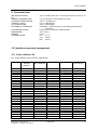
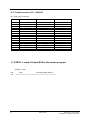
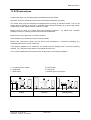
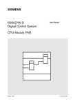
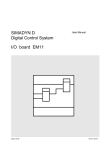
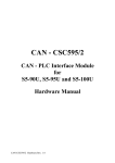
SIMADYN D
Digital Control System
User Manual
Interface board SS4
Edition 05.95
DK-Nr. 247341
User Manual, Interface board SS4
Edition
Edition status
1
Interface board SS4
08.94
2
Interface board SS4
05.95
Copying of this document and giving it to others and the use or
communication of the contents thereof is forbidden without express
authority. Offenders are liable to the payment of damages. All rights
are reserved in the event of the grant of a patent or the registration of
a utility model or design.
We have checked the contents of this Manual to ensure that they
coincide with the described hardware and software. However,
deviations cannot be completely ruled-out, so we cannot guarantee
complete conformance. However, the information in this document is
regularly checked and the necessary corrections included in
subsequent editions. We are thankful for any recommendations or
suggestions.
Contents
Contents
Warning information................................ ................................ ................................ .................... 1
1. Ordering information ................................ ................................ ................................ ...............3
2. Description................................ ................................ ................................ .............................. 3
3. Board design................................ ................................ ................................ ........................... 4
4. Serial interfaces ................................ ................................ ................................ ...................... 5
4.1. DUST interface ................................ ................................ ................................ ........5
4.2. Monitor interface................................ ................................ ................................ ......5
5. Connecting cables................................ ................................ ................................ ...................6
5.1. DUST interface ................................ ................................ ................................ ........6
5.2. Monitor interface................................ ................................ ................................ ......7
6. Applications ................................ ................................ ................................ ............................ 8
7. Screening................................ ................................ ................................ ................................ 8
8. Additional components................................ ................................ ................................ ............8
9. Technical data................................ ................................ ................................ ......................... 9
10. Interface connector assignment................................ ................................ ............................. 9
10.1. Serial interfaces X5................................ ................................ ................................ 9
10.2. Parallel interface CS7 - SS4/SS5................................ ................................ ...........10
11. STRUC L mask of board SS4 in the master program ................................ ............................ 10
12. Others................................ ................................ ................................ ................................ ...11
12.1. Attachments................................ ................................ ................................ ...........11
12.1.1. Block diagram................................ ................................ .......................... 11
12.1.2. Layout diagram................................ ................................ ........................ 11
12.1.3. Dimension drawing ................................ ................................ ..................11
13. ECB instructions................................ ................................ ................................ .................... 13
Siemens AG Dk-Nr. 247341
SIMADYN D Hardware User Manual
Edition 05.95
Warning information
Edition 05.95
Siemens AG Dk-Nr. 247341
SIMADYN D Hardware User Manual
Warning information
NOTE!
The information in this Manual does not purport to cover all details or variations in equipment, nor to provide
for every possible contingency to be met in connection with installation, operation or maintenance.
Should further information be desired or should particular problems arise which are not covered sufficiently for
the purchaser’s purposes, please contact your local Siemens office.
Further, the contents of this Manual shall not become a part of or modify any prior or existing agreement,
committment or relationship. The sales contract contains the entire obligation of Siemens. The warranty
contained in the contract between the parties is the sole warranty of Siemens. Any statements contained
herein do not create new warranties nor modify the existing warranty.
Warning information
WARNING!
Electrical equipment has components which are at dangerous voltage levels.
If these instructions are not strictly adhered to, severe bodily injury and material
damage can result.
Only appropriately qualified personnel may work on this equipment or in its
vicinity.
This personnel must be completely knowledgeable about all the warnings and
service measures according to this User Manual.
The successful and safe operation of this equipment is dependent on proper
handling, installation, operation and maintenance.
Siemens AG Dk-Nr. 247341
SIMADYN D Hardware User Manual
Edition 05.95
1
Warning information
Definitions
*
QUALIFIED PERSONNEL
*
DANGER
*
WARNING
*
CAUTION
*
NOTE
For the purpose of this User Manual and product labels, a „Qualified person“ is someone who is familiar with the
installation, mounting, start-up and operation of the equipment and the hazards involved. He or she must have
the following qualifications:
1. Trained and authorized to energize, de-energize, clear, ground and tag circuits and equipment in accordance
with established safety procedures.
2. Trained in the proper care and use of protective equipment in accordance with established safety
procedures.
3. Trained in rendering first aid.
For the purpose of this User Manual and product labels, „Danger“ indicates death, severe personal injury and/or
substantial property damage will result if proper precautions are not taken.
For the purpose of this User Manual and product labels, „Warning“ indicates death, severe personal injury or
property damage can result if proper precautions are not taken.
For the purpose of this User Manual and product labels, „Caution“ indicates that minor personal injury or
material damage can result if proper precautions are not taken.
For the purpose of this User Manual, „Note“ indicates information about the product or the respective part of the
User Manual which is essential to highlight.
CAUTION!
This board contains components which can be destroyed by electrostatic
discharge. Prior to touching any electronics board, your body must be electrically
discharged. This can be simply done by touching a conductive, grounded object
immediately beforehand (e.g. bare metal cabinet components, socket protective
conductor contact).
WARNING!
Hazardous voltages are present in this electrical equipment during operation.
Non-observance of the safety instructions can result in severe personal injury or
property damage.
It is especially important that the warning information in all of the relevant
Operating Instructions are strictly observed.
2
Edition 05.95
Siemens AG Dk-Nr. 247341
SIMADYN D Hardware User Manual
Ordering information
1. Ordering information
SS4: 6DD1688-0AD0
Interface board SS4
2. Description
Board SS4 is an interface board for DUST protocols. Corresponding to the specific configuration, it is
inserted in one of the three CS7 module slots. A maximum of three boards per carrier module can be
inserted.
The interface board has two serial interfaces. The configured DUST protocol can run on one
interface, and the second interface is used as service interface. The hex monitor runs on this
interface in the background. Both interfaces are available at the 26-pin sub D socket connector X5.
The following protocols can be configured on the DUST interface:
DUST1
Both interfaces are RS232 ( V24 ). If another physical interface is required for the DUST protocol, an
adaption to the 40-pin X51 connection can be realized by using an interface hybrid. If handshake
signals are required for operation via the RS232 interface, the S2 interface hybrid must be inserted. In
this case, there is a different pin assignment at connector X5 than for the standard RS232 interface.
The connection to the carrier module is realized via the parallel CS7-SS4/SS5 interface at the 48-pin
plug connector X1. In addition to the data-, address- and control bus, this connection is used to
establish the +5V, +15V and -15V board power supplies. Data transfer with the processor boards is
realized via a 16-kbyte dual port RAM, which is located on the carrier module.
A double test socket and double LED, assigned to each slot, are provided on the carrier module.
The LEDs have the following function:
LEDs
Function
H10 / H20 / H30
H11 / H21 / H31
dark
flashing
flashing
dark
flashing
dark
lit
lit
dark
dark
lit
lit
Processor not initialized
RAM test fault
SS4 initialized, waits for initialization from the
host
DUST initialized
Data transfer running
Software error
In addition to the reset function using the power supply, a local reset can be initiated by shortcircuiting the two test sockets at the processor of the appropriate interface board. This function has no
effect on the remaining subrack sections. It is necessary for testing the software and troubleshooting;
during standard operation, it is not permissible that a reset is initiated at these sockets.
Four LEDs on the interface module indicate the signal level of the send- and receive channels of the
two serial interfaces. They are used for troubleshooting and start-up and are not externally visible
under standard operating conditions with the board inserted. They have the following function:
Siemens AG Dk-Nr. 247341
SIMADYN D Hardware User Manual
Edition 05.95
3
Board design
LED
Function
H1
Dark/lit:
flickers/glows:
Hex monitor not transmitting
Hex monitor transmitting
H2
Dark/lit:
flickers/glows:
Hex monitor not transmitting
Hex-monitor transmitting
H3
Dark/lit:
flickers/glows:
DUST interface not transmitting
DUST interface transmitting
H4
Darl/lit:
flickers/glows:
DUST interface not receiving
DUST interface receiving
The 80-pin test connector X20 on the board is used for hardware diagnostics with a logic analyser.
The hardware functioning is monitored using a watchdog.
3. Board design
The boards provides the following hardware components.
Processor 80C186 ( 32 MHz )
EPROM ( 256 kbyte ) with firmware
Local processor RAM ( 64 kbyte )
Parallel interface to the carrier module
Two serial RS232 interfaces
Slot for hybrid interface circuit
Watchdog for NMI monitoring
LEDs for displaying the level of the serial receive- and transmit channels
Diagnostics connector for the logic analyser
Diagnostics using the Hex monitor
4
Edition 05.95
Siemens AG Dk-Nr. 247341
SIMADYN D Hardware User Manual
Serial interfaces
4. Serial interfaces
4.1. DUST interface
The DUST interface is RS232 (V24) as standard. If a different physical interface is required, this can
be implemented by using a SIMADYN D interface hybrid circuit. The appropriate module is inserted in
the 40-pin socket X51.
The following physical interfaces are possible:
Physical interface
Interface hybrid
RS232
RS232 ( with handshake )
20 mA ( TTY )
RS485
Standard version
Interface hybrid, SS2
Interface hybrid, SS1
Interface hybrid, SS3
Caution:
Observe the mounting position
4.2. Monitor interface
Parallel to the configured DUST interface, the Hex monitor runs in the background on the SS4. It can
be used for troubleshooting. This interface is at the same connector as the DUST interface for space
reasons.
If both interfaces are to be used, the user must create an adapter. In addition to the DUST cable, a
second cable with the appropriate connector for the service unit monitor interface is also connected at
connector X5 on the housing (Fig. 1).
The monitor interface is a RS232 interface and cannot be modified.
2 6 - p in h igh d e n s ity socket
to the SS4 in t e r f a c e m o d u le
SM8
Cable 4 * 0.5
SM3.1
DUST bus
Siemens AG Dk-Nr. 247341
SIMADYN D Hardware User Manual
2 5 - p in p lu g c o n n . for
t h e h e x m o n itor
Edition 05.95
5
Connecting cables
Fig. 1: Connecting a configured DUST interface and monitor interface at connector X5.
5. Connecting cables
5.1. DUST interface
Cables must be assembled according to the following diagrams when connecting the interface
module to a PG685, PG750, PG770 operator control unit. SIMADYN D has no pre-assembled cables
in its product spectrum. The SM8 parts set is required to connect to the interface module, and for the
connection to the communications partner, the appropriate parts set for the particular connector size.
A 4-core screened round cable is required (e.g. LICYC 4*0.5, Messrs. Metrofunk )
If the PG750/770 is operated as passive current interface (TTY), switches S3/2 and S3/3 must be
opened in the unit. For more detailed information refer to the system manual PG750/770
(Order No.: C79000-B8500-C630-D2 ).
wh
wh
gn
gn
ye bn
1
bn
ye
1
9
10
14
18
26
19
13
25
PG750/770 ( COM 1, 20mA ) passive
SS4 active
Fig. 2: SS4 at PG750/770 ( COM1 ) via the 20mA interface
wh
wh
gn
gn
ye
1
10
19
bn
bn
ye
1
9
18
26
14
SS4 passive
13
25
PG750/770 ( COM 1, 20mA ) active
Fig. 3: SS4 at PG750/770 ( COM1 ) via the 20mA interface
6
Edition 05.95
Siemens AG Dk-Nr. 247341
SIMADYN D Hardware User Manual
Connecting cables
wh
gn
wh
gn
bn
1
10
19
bn
1
9
18
26
14
SS4
13
25
PG750/770 ( COM 1, V24 )
Fig. 4: SS4 at PG750/770 ( COM1 ) via the V24 interface
wh
gn
gn
ye bn
1
10
19
wh
br
ye
1
9
14
18
26
SS4 active
13
25
PG685 ( AGinterface, 20mA ) passive
Fig. 5: SS4 at PG685 (PLC interface) via the 20mA interface
5.2. Monitor interface
The connection at connector X5 must be realized in the same connector housing as for the DUST
interface. The cable must be assembled according to the following diagram. SIMADYN D has no preassembled cables in its product spectrum.
gn
gn
ye bn
1
10
19
bn
ye
1
9
18
26
13
25
14
SS4
Hex-Monitor ( V24 )
Fig. 6: Pin assignment of the monitor interface
Siemens AG Dk-Nr. 247341
SIMADYN D Hardware User Manual
Edition 05.95
7
Applications
6. Applications
The interface board can be configured at any of the CS7 carrier module slots. Up to three interface
boards per CS7 can be configured. The sequence is irrelevant.
To ensure perfect operation, the board must screwed to the guiderails, even during start-up.
If the board is inserted in an adapter, the front panel must be connected with the housing through a
short cable.
It is not permissible that the board is inserted or withdrawn under voltage.
When calculating the total current drain of the board, the current drain of the inserted interface board
must be added to the SS4 values.
7. Screening
The bus cable screen should be grounded through a large surface area. The cable screens must be
connected to the grounding bar where the cable enters the cubicle. Further, the screen must be
connected to the connector housing. The connector is screwed to the boards.
The SIMADYN D EMC and installation guidelines are valid.
8. Additional components
Designation
Order No.
CS7 carrier module
6DD1662-0AB0
Interface hybrid circuit SS1 ( 20mA )
6DD1688-0AA0
Interface hybrid circuit SS2 ( RS232 )
6DD1688-0AB0
Interface hybrid circuit SS3 ( RS485 )
6DD1688-0AC0
Parts set SM8
( 26-pin, high density )
6DD1680-0AJ0
Parts set SM1.1
( 15-pin, plug )
6DD1680-0AB1
Parts set SM3.1
( 25-pin, plug )
6DD1680-0AD1
Parts set SM5
( 9-pin, plug )
6DD1680-0AF0
8
Edition 05.95
Siemens AG Dk-Nr. 247341
SIMADYN D Hardware User Manual
Technical data
9. Technical data
INSULATION GROUP
DC
AMBIENT TEMPERATURE
STORAGE TEMPERATURE
HUMIDITY CLASS
ALTITUDE RATING
MECHANICAL STRESSING
A acc. to VDE 0110 Para. 13, Group 2 at 24V DC, 15V DC, 5V
0 to +55 degrees C with natural air cooling
-40 to + 70 degrees C
F acc. to DIN 40040
S acc. to DIN 40040
Installation in permanent but not necessarily vibration-free
equipment
Inserted in a CS7 carrier module slot CS7
184 * 65 mm
0.5 kg
P5
0.4 A
P15
20 mA
N15
20 mA
PACKAGING SYSTEM
DIMENSIONS
WEIGHT
CURRENT DRAIN
10. Interface connector assignment
10.1. Serial interfaces X5
X5 ( 26-pin SUB D socket connector, high density )
Pin
RS232
standard
interface
RS232
with handshake
20 mA
RS485
RS232
( Hex monitor )
1
2
3
4
5
6
7
8
9
10
11
12
13
14
15
16
17
18
19
20
21
22
23
24
25
26
---------TxD
------------GND
---P15
------------RxD
---GND
---------P5
P5
---N15
----
---TxD
RxD
---CTS
DCD
GND
DCD
GND
---P15
---RTS
---RTxC
---RTxC
GND
---DTR
---P5
P5
TRxC
N15
----
------------------+Iq2
---GND
+TxD
P15
+Iq1
+RxD
-RxD
---------GND
-TxD
----Iq1
P5
P5
-Iq2
N15
----
---+RTS
+TRxD
---+TxD
+RTxC
+DCD
+RxD
GND
---P15
-------RTS
-TRxC
----TxD
GND
-RTxC
-DCD
-RxD
P5
P5
---N15
----
TxD
---------------------GND
---P15
------------------GND
---------P5
P5
---N15
RxD
Siemens AG Dk-Nr. 247341
SIMADYN D Hardware User Manual
Edition 05.95
9
10.2. Parallel interface CS7 - SS4/SS5
X1 ( 48-pin plug connector)
Pin
A
B
C
1
2
3
4
5
6
7
8
9
10
11
12
13
14
15
16
P5
AB1
AB4
AB7
AB10
L_RESET
DB0
DB3
DB6
DB9
DB12
DB15
L_INTDPR
L_RDYDPR
P15
M5
P5
AB2
AB5
AB8
AB11
CTCLK
DB1
DB4
DB7
DB10
DB13
L_DEN
DT_L_R
L_LED1
N15
M5
L_LOCK
AB3
AB6
AB9
AB12
AB13
DB2
DB5
DB8
DB11
DB14
L_CSMSB
L_CSLSB
L_LED2
L_INTUHR
M5
11. STRUC L mask of board SS4 in the master program
STRUC L mask
100
101
10
:SS4
"Interface board DUSTn"
*******************************************************************
Edition 05.95
Siemens AG Dk-Nr. 247341
SIMADYN D Hardware User Manual
Others
12. Others
12.1. Attachments
12.1.1. Block diagram
Block diagram
Fig. 7
12.1.2. Layout diagram
Layout diagram
2SE.465 688.9003.00 AO
12.1.3. Dimension drawing
Dimension drawing
Siemens AG Dk-Nr. 247341
SIMADYN D Hardware User Manual
3SE.465 688.9003.00 MB
Edition 05.95
11
Others
Parallelbus 48-pol.
parallel bus 48 core
X1
Quarz
oscillator
32 MHz
Adressbus
address bus
Adresslatch
address latch
Datenbus
data bus
Datentreiber
data driver
Steuerbus
control bus
Steuersignale
control signals
Prozessor
80C186
Control - Logik
control logic
Chip Select
Decoder
DMA-Controller
Watchdog
X20
Serial Controller
SCC
Channel 1
EPROM
256 kbyte
Diagnosestecker
diagnostic plug
RAM
64 kbyte
Channel 2
40-polige Fassung fuer
Schnittstellenhybrid
40 way socket for
interface hybrid
Standardschnittsttelle
Serviceschnittsttelle
standard interface
service interface
RS232
RS232
Control-LED
X51
X5
Serierlle Schnittstelle 26 - pol. Sub D ( high density )
serial interface 26 pin Sub D ( high density )
Fig. 7: SS4 block diagram
12
Edition 05.95
Siemens AG Dk-Nr. 247341
SIMADYN D Hardware User Manual
ECB instructions
13. ECB instructions
Components which can be destroyed by electrostatic discharge (ECB)
Generally, electronic boards should only be touched when absolutely necessary.
The human body must be electrically discharged before touching an electronic board. This can be
simply done by touching a conductive, grounded object directly beforehand (e.g. bare metal cubicle
components, socket outlet protective conductor contact.
Boards must not come into contact with highly-insulating materials - e.g. plastic foils, insulated
desktops, articles of clothing manufactured from man-made fibers.
Boards must only be placed on conductive surfaces.
When soldering, the soldering iron tip must be grounded.
Boards and components should only be stored and transported in conductive packaging (e.g.
metalized plastic boxes, metal containers).
If the packing material is not conductive, the boards must be wrapped with a conductive packing
material, e.g. conductive foam rubber or household aluminum foil.
The necessary ECB protective measures are clearly shown in the following diagram.
a = Conductive floor surface
b = ECB table
c = ECB shoes
Seated
Siemens AG Dk-Nr. 247341
SIMADYN D Hardware User Manual
d = ECB overall
e = ECB chain
f = Cubicle ground connection
Standing
Edition 05.95
Standing/sitting
13
ECB instructions
14
Edition 05.95
Siemens AG Dk-Nr. 247341
SIMADYN D Hardware User Manual
ECB instructions
Drives and Standard Products
Motors and Drives Systems Group
Postfach 3269, D-91050 Erlangen
Siemens AG Dk-Nr. 247341
SIMADYN D Hardware User Manual
System-Based
Technology
Edition 05.95
15