1
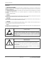
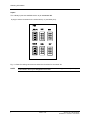
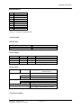
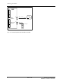
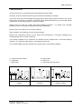
SIEMENS
SIMADYN D
Digital Control System
User Manual
CPU Module PM5
Edition 10.97
DK-No.221841
User Manual, CPU Module PM5
Edition
1
Status
CPU Module PM5
Copying of this document and giving it to others and the use or
communication of the contents thereof is forbidden without express
authority. Offenders are liable to the payment of damages. All rights
are reserved in the event of the grant of a patent or the registration of
a utility model or design.
We have checked the contents of this Manual to ensure that they
coincide with the described hardware and software. However,
deviations cannot be completely ruled-out, so we cannot guarantee
complete conformance. However, the information in this document is
regularly checked and the necessary corrections included in
subsequent editions. We are thankful for any recommendations or
suggestions.
10.97
Warning information
NOTE!
The information in this Manual does not purport to cover all details or variations in equipment, nor to provide
for every possible contingency to be met in connection with installation, operation or maintenance.
Should further information be desired or should particular problems arise which are not covered sufficiently for
the purchaser’s purposes, please contact your local Siemens office.
Further, the contents of this Manual shall not become a part of or modify any prior or existing agreement,
committment or relationship. The sales contract contains the entire obligation of Siemens. The warranty
contained in the contract between the parties is the sole warranty of Siemens. Any statements contained
herein do not create new warranties nor modify the existing warranty.
Warning information
WARNING!
Electrical equipment has components which are at dangerous voltage levels.
If these instructions are not strictly adhered to, this can result in severe bodily
injury and material damage.
Only appropriately qualified personnel may work on this equipment or in its
vicinity.
This personnel must be completely knowledgeable about all the warnings and
service measures according to this User Manual.
The successful and safe operation of this equipment is dependent on proper
handling, installation, operation and maintenance.
Siemens AG DK-No.221841
SIMADYN D Hardware User Manual
Edition 10.97
1
Warning information
Definitions
*
QUALIFIED PERSONNEL
*
DANGER
*
WARNING
*
CAUTION
*
NOTE
For the purpose of this User Manual and product labels, a ”Qualified person” is someone who is familiar with the
installation, mounting, start-up and operation of the equipment and the hazards involved. He or she must have
the following qualifications:
1. Trained and authorized to energize, de-energize, clear, ground and tag circuits and equipment in accordance
with established safety procedures.
2. Trained in the proper care and use of protective equipment in accordance with established safety
procedures.
3. Trained in rendering first aid.
For the purpose of this User Manual and product labels, ”Danger” indicates death, severe personal injury and/or
substantial property damage will result if proper precautions are not taken.
For the purpose of this User Manual and product labels, ”Warning” indicates death, severe personal injury or
property damage can result if proper precautions are not taken.
For the purpose of this User Manual and product labels, ”Caution” indicates that minor personal injury or
material damage can result if proper precautions are not taken.
For the purpose of this User Manual, ”Note” indicates information about the product or the respective part of the
User Manual which is essential to highlight.
CAUTION!
This board contains components which can be destroyed by electrostatic
discharge. Prior to touching any electronics board, your body must be electrically
discharged. This can be simply done by touching a conductive, grounded object
immediately beforehand (e.g. bare metal cabinet components, socket protective
conductor contact).
WARNING!
Hazardous voltages are present in this electrical equipment during operation.
Non-observance of the safety instructions can result in severe personal injury or
property damage.
It is especially important that the warning information in all of the relevant
Operating Instructions are strictly observed.
2
Edition 10.97
Siemens AG DK-No.221841
SIMADYN D Hardware User Manual
Ordering information
Ordering information
Order No.
6DD1600-0AJ0
Description
The CPU module processes general open- and closed-loop tasks. Four binary inputs are available.
Performance data
Computational performance: 32 MHz, 32 bit RISC processor
DRAM 4 Mbytes (EDO)
SRAM 64 Kbytes
This CPU module permits fast cycle times of 0.1 ms.
A typical application (e. g. control loop) can be configured in approx.0.6 ms.
DRAM
The DRAM contains:
· program code (is loaded and expanded when the memory module is initialized)
· data memory for the operating system, communications, message buffer, trace function
If the DRAM is not large enough for complex applications, a PM6 (with 8Mbyte DRAM) must
be used.
SRAM, buffered
The buffered SRAM (using either a battery in the subrack or an external battery) contains the
following data, which are to be saved during and after a power failure:
· operating system error diagnostics (”exception buffer”)
· max. 1000 process quantities configured with function block SAV
· data recorded/traced using the message system or trace function (can be optionally
configured on the SRAM)
Programming
The program, running on the CPU module, is configured on a PC using STEP7/HWConfig and CFC.
This is then loaded into an MS5 program memory module (or MS51).
MS5, MS51
MS5, 2 Mbyte Flash-EPROM,. 8 Kbyte EEPROM
MS55, 2 Mbyte SRAM,
8 Kbyte EEPROM
MS51, 4 Mbyte Flash-EPROM, 8 Kbyte EEPROM
A MS51 memory module which could be used with the PM5 may only be used up to approx. 50 % so
that the expanded code can be accepted on the PM5.
Serial service interface
An RS 232 interface (V.24) with service protocol DUST1 with 19.2 kbd is permanently installed in
connector X01 (9-pin sub-D socket). It is used to test and commission the user program.
Siemens AG DK-No.221841
SIMADYN D Hardware User Manual
Edition 10.97
3
Ordering information
Inputs
The 4 binary inputs are available at the 10-pin connector X5.
A plug-in socket is inserted in the socket X5A (1..4) and X5A (5..8).
Bin.In1..4
Fig. 4-1 Slots for coding connectors to select the functions for connector X5
NOTE
4
Only one coding connector may be inserted in each socket row (pins 1..4 or pins 5..8).
A connection can only be assigned one function.
Edition 10.97
Siemens AG DK-No.221841
SIMADYN D Hardware User Manual
Ordering information
7-segment display
In normal operation, the configured number of the CPU module (1...8) is displayed. When an error
occurs, a letter is displayed, which refers to the error type.
Possible operating- and error statuses:
Display Operating- and error statuses
1...8
A
-
.
0
b
C
E
H
Configured number of the CPU module in normal operation
Display caused by the user software (configuring) has no influence on
program execution
Initialization phase
Individual initialization steps are displayed with increasing numbers during
the run-up phase
5V available; no program is being executed
Initialization error due to erroneous or incorrectly inserted modules for the
actual software which has been configured:
· flashing ”0”: Error on this module
· steady ”0”: Error on other modules
· continuous: Error when loading the system software
Monitoring error
(e. g. missing, discharged buffer battery, overload, binary outputs)
Erroneous configured communications or connection
Operating system alarms, generally, time overrun
Fatal system error due to hardware or software problems which resulted in
a program crash:
· flashing ”H”: Fault/error on this module
· steady ”H”: Fault/error on another module
Display can
be deleted
with key
yes
-
no
yes
no
yes
no
Button S1
The button has 2 functions:
· Deleting the error display:
By depressing button S1, sporadic errors (”E”) or non-critical errors (”b”) appearing in the
display can be deleted.
If another error is present, this is displayed after the first has been acknowledged.
· Binary signal input with function block ASI
Real-time clock
Resolution, 0.1 ms; e. g. to time stamp messages
Software protection
A plug-in socket for a 28-pin EPLD device is provided on the module (ALTERA company) so that the
user program can be copy-protected (”Hardlock PAL”).
Using a special function block, this EPLD device can be checked and program stopped if the code is
missing or is incorrect.
Additional information on request.
Supplementary components
Siemens AG DK-No.221841
SIMADYN D Hardware User Manual
Edition 10.97
5
Ordering information
· MS5, MS55 and MS51 program memory modules
· cable SC57 for PC connection, 9-core, 5 m
· cable SC7 to connect an interface module, 10-core, 2 m
If additional input/output signals and other functions are required, then these can be implemented by
inserting a maximum of 2 expansion modules; the types are subsequently listed:
· IT41
· IT42
· ITDC
· ITSL
Application information and noise immunity
· operation without fan is possible
· noise-immune operation is only possible if the module is tightly screwed into the subrack
· do not insert or withdraw the module when the subrack is powered-up
Other information
For more information regarding EMC and ambient conditions, refer to the Section ”General technical
data”
Connector assignments
Serial interface X01
RS 232
Pin
2
3
5
7
Designation
RxD
TxD
M
RTS
Comment
Receive data
Transmit data
Ground
Request to send
(”1”)
Table 4-2 Connector assignment X01
6
Edition 10.97
Siemens AG DK-No.221841
SIMADYN D Hardware User Manual
Ordering information
Binaryinputs X5
Pin
1
2
3
4
5
6
7
8
9
10
binary input
Binary input 1
Binary input 2
Binary input 3
Binary input 4
Ground
Table 4-3 Connector assignment X5
Technical data
General data
No. of slots occupied
Dimensions W x H x D [mm]
Weight
1
20.14 x 233.4 x 220
Approx. 0.5 kg
Power supply
Rated voltage
+5 V
+15 V
-15 V
24 V (external)
Minimum
+4.74 V
+14.4 V
-15.6 V
20 V
Maximum
+5.25 V
+15.6 V
-14.4 V
30 V
Typical current drain
1200 mA
35 mA
35 mA
100 mA + binary output currents
Binary inputs
No.
4 coding plug at socket X5A (1..4)
and X5A (5..8)
+24 V rated voltage
Input voltage
for 0 signal
for 1 signal
-1 V to +6 V or binary inputs open-circuit
+13 V to +33 V
for 0 signal
for 1 signal
0 mA
3 mA typ.
Max. 20 µs
No;
only via SB60, SB61 interface modules
Input current
Input delay
Electrical isolation
Connection diagram
Siemens AG DK-No.221841
SIMADYN D Hardware User Manual
Edition 10.97
7
Ordering information
PM5
CBus
Bediengerät
(PC)
X01
serielle
Schnittstelle
(Service)
LBus
4 Binäreing. BE,
alarmfähig
9pol
SC57 ( Teilstück 1) je 9pol.
COM1/2
l=5m
X5
10pol
SC7 (je 10pol.)
l=2m
8 Eingänge
SB10
SB60
SB61
oder
SU12
Fig. 4-2 Connecting cables and interface modules
8
Edition 10.97
Siemens AG DK-No.221841
SIMADYN D Hardware User Manual
ESD instructions
1. ESD instructions
Components which can be destroyed by electrostatic discharge (ESD)
Generally, electronic boards should only be touched when absolutely necessary.
The human body must be electrically discharged before touching an electronics board. This can be
simply done by touching a conductive, grounded object directly beforehand (e.g. bare metal cubicle
components, socket outlet protective conductor contact).
Boards must not come into contact with highly-insulating materials - e.g. plastic foils, insulated
desktops, articles of clothing manufactured from man-made fibers.
Boards must only be placed on conductive surfaces.
When soldering, the soldering iron tip must be grounded.
Boards and components should only be stored and transported in conductive packaging (e.g.
metalized plastic boxes, metal containers).
If the packing material is not conductive, the boards must be wrapped with a conductive packing
material, e.g. conductive foam rubber or household aluminum foil.
The necessary ESD protective measures are clearly shown in the following diagram.
a = Conductive floor surface
b = ESD table
c = ESD shoes
Seated
Siemens AG DK-No.221841
SIMADYN D Hardware User Manual
d = ESD overall
e = ESD chain
f = Cabinet ground connection
Standing
Edition 10.97
Standing / sitting
9
ESD instructions
Drives and Standard Products
Motors and Drive Systems Group
Postfach 3269, D-91050 Erlangen
10
SystemBased Drive
Technology
Edition 10.97
Siemens AG DK-No.221841
SIMADYN D Hardware User Manual