1
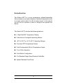
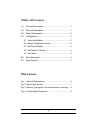
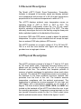
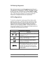
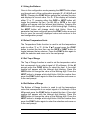
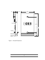
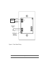
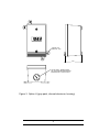
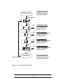
DEVAR Inc. Model d-RTTI User Manual Introduction The Model d-RTTI is a room temperature indicator/transmitter that provides an accurate indication of ambient temperature with a numeric readout and a 4 to 20 mA output signal. In this manual you will find an overview of how to configure and operate this device. The Model d-RTTI includes the following features: 4 Digit Red LED Temperature Display Fahrenheit or Centigrade Operating Modes -40 To 180 ºF or -40 To 82 ºC Operating Ranges Precision RTD Temperature Sensor Field Configurable 4/20 mA Temperature Output True 2-Wire Operation Push-Button Configuration Fits Standard Single Gang Electrical Outlet Box Splash Resistant Front Panel i Table of Contents 1.0 General Description.................................................... 1 2.0 Physical Description................................................... 1 3.0 Start Up Sequence..................................................... 2 4.0 Configuration........................................................... 2 4.1 Using the Buttons.................................................... 3 4.2 Select Temperature Scale....................................... 3 4.3 Set Top of Range.................................................... 3 4.4 Set Bottom of Range............................................... 3 4.5 Set Offset................................................................ 4 5.0 Error Messages.......................................................... 4 6.0 Specifications............................................................. 4 Illustrations Fig. 1. General Dimensions................................................ 6 Fig. 2. Rear Panel Wiring.................................................... 7 Fig. 3 Option H (gray paint, die cast aluminum, housing).. 8 Fig. 4. Configuration Flowchart........................................... 9 ii 1.0 General Description The Model d-RTTI Digital, Room-Temperature, TransmitterIndicator is designed to accurately sense and display ambient room temperature and provide a 4 to 20 mA output signal that is proportional to the measured temperature to within ±0.1 ºF. The d-RTTI displays ambient room temperature across an operating range of -40ºF to 180ºF or -40ºC to 82ºC. The standard factory configuration scales the 4 to 20 mA output signal to represent a temperature span of 0 to 100ºF. The user can easily reconfigure the unit in the field by using the three push button switches located on the backside of the device. A precision 1000 ohm RTD sensor is used to detect the ambient temperature. An option is also available that will accept its input from an external 1000 ohm platinum RTD sensor. The d-RTTI operates on a supply voltage of 10 to 28 Volts DC. This is a true two wire devices with signal and power being provided over a single pair of wires. 2.0 Physical Description The d-RTTI enclosure consists of a beige 4.7” high by 2.8” wide by 3/8” thick plastic plate. Captivated mounting screws and a gasket seal are provided to attach the unit to a single-gang electrical outlet box. The sealed front faceplate provides a measure of splash resistance for applications where wash down is required. The internal RTD temperature sensor is mounted on the backside of the black anodized aluminum heatsink that protrudes from the front of the unit. The heatsink ensures temperature compliance with the ambient environment. The temperature is indicated on a seven-segment, 0.4-inch high, red LED display, with a temperature resolution of one tenth of a degree. The three buttons labeled FUNC, INCR, and NEXT are located on the backside of the d-RTTI and allow the user to set the operating parameters. Compression screw-terminals on the rear provide connection points for the 4 to 20mA output wires and the optional remote sensor. Refer to the figures 1 and 2. 1 3.0 Startup Sequence The start up sequence occurs after applying power to the unit. The sequence is: all segments lit “8.8.8.8.”; then “type”, followed by “rtti”; then “ver”; followed by two numbers ddmm and yyyy that represent the day, month, and year of the revision; and then “run”. After the startup sequence is complete the detected temperature is displayed and the unit is operational. 4.0 Configuration To enter the configuration mode press all three buttons while powering up the unit or, while the d-RTTI is operational, press and hold all three buttons for approximately five seconds. The unit will enter the startup sequence by lighting all segments “8.8.8.8.” and then displaying “COnF”. Pressing any button at this point will produce the first Configuration Prompt on the list of configurable operating parameters below. Configuration Parameters Prompt Operation Selects whether the temperature will be displayed in ºF or ºC Selects the temperature value that will produce a 20 mA output Selects the temperature value that will produce a 4 mA output Adds a small amount of offset or zero shift to the displayed temperature; this value is normally set to zero but can be used to make fine adjustments to the temperature measurement 2 4.1 Using the Buttons Once in the configuration mode pressing the NEXT button steps you through each of the configuration prompts (F z C, HI, LO and OFFS). Pressing the FUNC button selects the indicated function and displays its current value. For F z C the display will indicate either ºC or ºF, pressing either the INCR or NEXT button will toggle the between the two. For HI, LO or OFFS a four digit number will appear with the leftmost digit blinking. Pressing the INCR button will change the value of the blinking digit. Pressing the NEXT button will change which digit blinks. Once the parameter has been configured press the FUNC button a second time to save the currently displayed value and continue to the next configuration prompt. 4.2 Select Temperature Scale The Temperature Scale function is used to set the temperature scale to either ºF or ºC. At the F z C prompt press the FUNC button to select the item then use the INCR or NEXT button to toggle between the two choices. Press the FUNC button again to enter the selection and move on to the next prompt. 4.3 Set Top of Range The Top of Range function is used to set the temperature value that corresponds to an output signal of 20 milliamps. At the HI prompt press the FUNC button to select the item. A four-digit number will appear with the leftmost digit blinking. Press the INCR button to change the value of the blinking digit. Press the NEXT button to change which digit blinks. Edit the number then press the FUNC button again to enter the selection and move on to the next prompt. 4.4 Set Bottom of Range The Bottom of Range function is used to set the temperature value that corresponds to an output signal of 4 milliamps. At the LO prompt press the FUNC button to select the item. A four digit number will appear with the leftmost digit blinking. Press the INCR button to change the value of the blinking digit. Press the NEXT button to change which digit blinks. Edit the number then press the FUNC button again to enter the selection and move on to the next prompt. 3 4.5 Set Offset The Set Offset function is used to shift the temperature reading up or down by a small amount as a fine temperature adjustment. At the OFFS prompt press the FUNC button to select the item. A three digit number will appear with the leftmost digit blinking. Press the INCR button to change the value of the blinking digit. Press the NEXT button to change which digit blinks. Edit the number then press the FUNC button again to enter the selection. After the FUNC button is pressed the Startup Sequence will complete and the unit will go into the operating mode. The maximum offset adjustment is ±10 degrees. 5.0 Error Messages Setting the HI or LO value to a number that falls outside of the operating range of the instrument will cause Err to be displayed and the unit will return to the edit screen so that the number can be re-entered. Setting the 4 to 20 mA output span (span = HI – LO) to a value of less than 35 ºF or 20 ºC will cause SPAN Err to be displayed, press any button to return to the HI prompt so that the error can be corrected. Setting the OFFS value to a number greater than ± 10 will cause Err to be displayed and the unit will return to the edit screen so that the number can be re-entered. 6.0 Specifications GENERAL Display: Housing: Material: Junction Box Field Wiring Sensor: Open RTD: Temp. Range: 4 Digit LED with 0.4 inch high, red characters Splash resistant faceplate with rear gasket seal ABS Plastic faceplate with polycarbonate window and black anodized aluminum heat sink Die Cast, Gray Painted, Aluminum (Option -H) Screw Compression Term Block (Max Torque: 7 lb/in) 1000 Ohm Platinum RTD, Conforms to DIN Standard EN 60751, Class A Output goes upscale -40 to 180 ºF (-40 to 82 ºC) 4 RFI Immunity: Rated class 3-C DISPLAY Range: Accuracy: Thermal Effect: -40 to 180 ºF or -40 to 82 ºC ±0.5 ºF (±0.9 ºC) at 77 ºF (25 ºC) Zero Shift: ±0.002 X (Reading-77 ºF) Span Shift: ±0.004 X (Reading-77 ºF) MILLIAMP OUTPUT Range: 4 to 20 mA Accuracy: ±0.7 ºF (±0.4 ºC) + 0.1% of Span Thermal Effect: Zero: Display Shift ± 0.01% of Span per ºF Span: Display Shift ± 0.01% of Span per ºF Supply: 10 to 28 VDC Max Load: R ohms = (V supply - 10V) / 0.020A Supply effect: 0.01% of Span per Volt Load Effect: 0.05% of Span per 300 Ohm Change DEFAULT CALIBRATION Display: Loop: -40 to 180 ºF 4 to 20 mA Represents 0 to 100 ºF FIELD CALIBRATION Display: Output Loop: Output Limits: Method: -40 to 180 ºF or -40 to 82ºC The HI and Lo Milliamp outputs must be set to represent temperatures within the displayable range (-40 to 180 ºF or -40 to 82ºC) Maximum milliamp span: 220 ºF or 122 ºC Minimum milliamp span: 35 ºF or 20 ºC Maximum offset adjustment: ±10 degrees Three push buttons on back of panel PRODUCT CODING Standard Unit: d-RTTI (Default Calibration) Custom Cal: d-RTTI - [Temp at 4 mA / Temp at 20 mA] Options: -R No internal sensor, Unit accepts input from external 1000 ohm platinum RTD -H Add Die Cast, Gray Painted, Aluminum Housing 5 1/2" 0.375 2.800 PLATE 3 9/32 4.700 SCREW RETAINER 0.760 HEATSINK GASKET Figure 1. General Dimensions 6 PS+ LOAD SPARE LOAD PS- + POWER SUPPLY - REMOTE RTD NEXT INCR FUNC OPTION -R REMOTE SENSING Figure 2. Rear Panel Wiring 7 SWIVEL LUG HOLE DIA. 0.25" 2.55 1/2" NPT PORT, THREE PLACES TOP, BOTTOM AND CENTER BACK INCLUDES TWO 1/2" NPT PLUGS Figure 3. Option H (gray paint, die cast aluminum, housing) 8 TO ENTER CONFIGURATION ON POWER UP, PRESS AND HOLD FUNC, INCR AND NEXT WHILE APPLYING POWER POWER ON FUNC, INCR, NEXT NEXT FUNC SET TEMPERATURE SCALE USE INCR OR NEXT TO TOGGLE BETWEEN ºF AND ºC; USE FUNC TO ACCEPT NEXT FUNC SET 20 mA TEMPERATURE USE INCR TO EDIT FLASHING DIGIT; USE NEXT TO SELECT DIGIT; USE FUNC TO ACCEPT NEXT FUNC SET 4 mA TEMPERATURE USE INCR TO EDIT FLASHING DIGIT; USE NEXT TO SELECT DIGIT; USE FUNC TO ACCEPT NEXT FUNC SET TEMPERATURE OFFSET USE INCR TO EDIT FLASHING DIGIT; USE NEXT TO SELECT DIGIT; USE FUNC TO ACCEPT NEXT TO ENTER CONFIGURATION FROM THE OPERATING MODE, PRESS AND HOLD FUNC, INCR AND NEXT FOR 5 SECONDS OPERATE FUNC, INCR, NEXT Figure 4. Configuration Flow Chart 9 WARRANTY DEVAR INC. WARRANTS THIS PRODUCT AGAINST FAILURE AS A RESULT OF DEFECTS IN MATERIAL OR WORKMANSHIP FOR A PERIOD OF TWO YEARS. Should this product prove to be defective in material or workmanship during the warranty period, Devar Inc. will, at its discretion, repair or replace the defective item at no charge to the customer. Products that are damaged by accident, misuse, fire, water, lightning or other acts of nature are not covered under this warranty. Also not covered, is damage, due to shipping, installation, incorrect wiring or any other cause not related to a product defect. Unauthorized product modification, repair or attempted repair, or serial number modification will void the warranty. DEVAR INC. 706 Bostwick Ave. Bridgeport Ct. 06605 USA 800 566 6822, www.devarinc.com MODEL d-RTTI Rev A