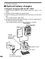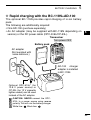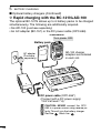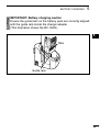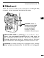
1
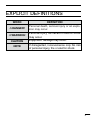
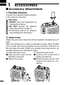
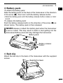
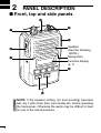
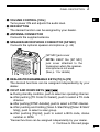
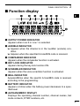
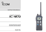
INSTRUCTION MANUAL VHF TRANSCEIVER iF51 UHF TRANSCEIVER iF61 P0 P1 P2 P3 This illustration shows the IC-F51. FOREWORD READ ALL INSTRUCTIONS carefully and completely before using the transceiver. SAVE THIS INSTRUCTION MANUAL— This instruction manual contains important operating instructions for the IC-F51 and IC-F61 uhf transceiver. vhf transceiver This instruction manual includes some functions which are usable only when they are pre-programmed by your dealer. Ask your dealer for details. OPERATING NOTES • When transmitting with a portable radio, hold the radio in a vertical position with its microphone 5 to 10 centimeters away from your mouth. Keep the antenna at least 2.5 centimeters from your head and body. • If you wear a portable two-way radio on your body, ensure that the antenna is at least 2.5 centimeters from your body when transmitting. Icom, Icom Inc. and Icom logo are registered trademarks of Icom Incorporated (Japan) in Japan, the United States, United Kingdom, Germany, France, Spain, Russia and/or other countries. i EXPLICIT DEFINITIONS WORD DEFINITION RDANGER! Personal death, serious injury or an explo sion may occur. RWARNING! Personal injury, fire hazard or electric shock may occur. CAUTION NOTE Equipment damage may occur. If disregarded, inconvenience only. No risk of personal injury, fire or electric shock. ii INTRINSIC SAFETY Versions of the IC-F51/F61 which display the “EX” marking on the serial number seal. The approval rating for these models are II2GD Ex ib IIA T3 and Ex tD A21 T160°C IP67. WARNING! NEVER charge the BP-227AXD (with/without the transceiver) in an explosive atmosphere. The optional battery chargers are not approved as Intrinsically Safe. When the transceiver is used in a hazardous area, the BP-227AXD MUST be attached, either the jack cover or HM-138 MUST be attached to the speaker-microphone connector. KEEP the transceiver and the BP-227AXD clean to avoid any risk of ignition due to the build-up of electrostatic charges. Repair of Icom radios should only be carried out by authorized Icom distributors. In particular, repair of ATEX approved radios can ONLY be done by Icom to maintain the intrinsically safe rating. NEVER attempt to repair an ATEX approved radio. Only Icom has the repair expertise and procedures to maintain the ATEX approval. Contact your Icom distributor or authorised dealer for details. iii The ATEX standard is described on the 94/9/EC sticker (Ex Marking) and BP-227AXD as below. * The following illustrations show the IC-F51/F61. BP-227AXD • DO NOT OPEN WHEN AN EXPLOSIVE ATMOSPHERE MAY BE PRESENT. • DO NOT CHARGE THE BATTERY IN HAZARDOUS LOCATION. iv PRECAUTIONS RDANGER! NEVER short the terminals of the battery pack. RDANGER! Use and charge only specified Icom battery packs with Icom radios or Icom chargers. Only Icom battery packs are tested and approved for use with Icom radios or charged with Icom chargers. Using third-party or counterfeit battery packs or chargers may cause smoke, fire, or cause the battery to burst. RWARNING! NEVER hold the transceiver so that the antenna is very close to, or touching exposed parts of the body, especially the face or eyes, while transmitting. The transceiver will perform best if the microphone is 5 to 10 cm away from the lips and the transceiver is vertical. RWARNING! NEVER operate the transceiver with a headset or other audio accessories at high volume levels. Hearing experts advise against continuous high volume operation. If you experience a ringing in your ears, reduce the volume level or discontinue use. CAUTION: NEVER connect the transceiver to a power source other than the BP-227AXD. Such a connection will ruin the transceiver. CAUTION: MAKE SURE the flexible antenna and battery pack are securely attached to the transceiver, and that the antenna and battery pack are dry before attachment. Exposing the inside of the transceiver to water will result in serious damage to the transceiver. DO NOT push the PTT when not actually desiring to transmit. v DO NOT use or place the transceiver in direct sunlight or in areas with temperatures below –20°C or above +55°C. The basic operations, transmission and reception of the transceiver, are guaranteed within the specified operating temperature range. However, the LCD display may be operate correctly, or show an indication in the case of long hours of operation, or after being placed in extremely cold areas. DO NOT modify the transceiver. The transceiver warranty does not cover any problems caused by unauthorized modification. DO NOT use harsh solvents such as benzine or alcohol when cleaning, as they will damage the transceiver surfaces. BE CAREFUL! The transceiver will become hot when operating it continuously for long periods of time. BE CAREFUL! The transceiver meets IP67* requirements for dust-tight and waterproof protection. However, once the transceiver has been dropped, dust-tight and waterproof protection cannot be guaranteed because of possible damage to the transceiver’s case or the waterproof seal. * Only when the battery pack and jack cover are attached. MAKE SURE to turn the transceiver power OFF before connect ing the supplied/optional equipment. MAKE SURE the flexible antenna and battery pack are securely attached to the transceiver, and that the antenna and battery pack are dry before attachment. Exposing the inside of the transceiver to water will result in serious damage to the transceiver. vi TABLE OF CONTENTS FOREWORD......................................................................................... i OPERATING NOTES............................................................................ i EXPLICIT DEFINITIONS...................................................................... ii INTRINSIC SAFETY.............................................................................iii PRECAUTIONS.................................................................................... v TABLE OF CONTENTS.......................................................................vii SUPPLIED ACCESSORIES...............................................................viii 1 ACCESSORIES.......................................................................... 1–2 ■ Accessory attachments............................................................... 1 vii 2 PANEL DESCRIPTION................................................................. 11 ■ Front, top and side panels........................................................... 3 ■ Function display........................................................................... 6 ■ Programmable function keys....................................................... 7 3 CONVENTIONAL OPERATION.............................................. 12–18 ■ Turning power ON...................................................................... 12 ■ Channel selection...................................................................... 12 ■ Call procedure........................................................................... 13 ■ Receiving and transmitting........................................................ 14 ■ Scrambler function..................................................................... 17 ■ User set mode........................................................................... 18 4 BIIS OPERATION................................................................... 19–34 ■ Default setting............................................................................ 19 ■ Receiving a call......................................................................... 20 ■ Transmitting a call...................................................................... 23 ■ Receiving a message................................................................ 26 ■ Transmitting a status.................................................................. 29 ■ Transmitting an SDM.................................................................. 30 ■ Position data transmission......................................................... 31 ■ Printer connection...................................................................... 32 ■ PC connection........................................................................... 32 ■ Digital ANI.................................................................................. 32 ■ Auto emergency transmission................................................... 33 ■ Stun function.............................................................................. 33 ■ BIIS indication............................................................................ 34 ■ Priority A channel selection....................................................... 34 5 BATTERY CHARGING........................................................... 35–44 n Caution...................................................................................... 35 ■ Optional battery chargers.......................................................... 39 6 SPEAKER-MICROPHONE..................................................... 45–46 ■ Optional HM-138 description..................................................... 45 ■ Attachment................................................................................ 46 7 OPTIONS................................................................................ 47–48 8 ATEX CAUTIONS.................................................................... 49–51 9 CE................................................................................................. 52 SUPPLIED ACCESSORIES The following accessories are supplied: Qty. • Flexible antenna……………………………………………………… 1 • Battery pack… ……………………………………………………… 1 • Jack cover… ……………………………………………………… 1 set • Belt clip… ………………………………………………………… 1 set • Function name stickers* (KEY-STICKER)………………………… 1 *There are no names on the programmable function keys since the functions can be freely assigned to [P0] to [P3], [Red], [ ] and [ ] keys. Attach the supplied function name stickers above the appropriate keys for easy recognition of that key’s assigned function. viii 1 ACCESSORIES ■ Accessory attachments D Flexible antenna Connect the supplied flexible antenna to the antenna connector. CAUTION: • NEVER carry the transceiver by holding the antenna. • DO NOT connect the antenna other than listed on page 47. • Transmitting without an antenna may damage the transceiver. ï Jack cover Attach the jack cover when the optional speaker-microphone is not used. When the transceiver is used in a hazardous areas, either the jack cover or HM-138 must be attached to the connector. Failure to do this will make the radio ATEX non-compliant and may result in an accident during use in hazardous areas. To detach the jack cover: To attach the jack cover: q Insert the jack cover into the q U nscrew the screw with a phillips screwdriver. [SP MIC] connector. w Detach the jack cover for the w Tighten the screw. speaker-microphone connection. q q w 1 w ACCESSORIES 1 ï Battery pack To attach the battery pack: Slide the battery pack on the back of the transceiver in the direction of the arrow (q), then lock it with the battery release button. • Slide the battery pack until the battery release button makes a ‘click’ sound. To release the battery pack: Push the battery release button in the direction of the arrow (w) as shown below. The battery pack is then released. EVER release or attach the battery pack when the transceiver N is wet or soiled. This may result in water or dust getting into the transceiver/battery pack and may damage the transceiver. Battery pack 1 2 3 4 5 6 7 8 9 q 10 Battery release button w 11 12 13 14 D Belt clip Attach the belt clip to the back of the transceiver with the supplied screws. Supplied screws 15 16 17 18 19 20 2 2 PANEL DESCRIPTION ■ Front, top and side panels w e q r Speaker (See the following NOTE.) Microphone Function display (p. 7) i u t y OTE: If the speaker netting (for dust proofing) becomes N wet, dry it with a hair drier (cool mode) etc. before operating the transceiver. Otherwise the audio may be difficult to hear for loss of the sound pressure. 3 PANEL DESCRIPTION 2 1 q VOLUME CONTROL [VOL] Turns power ON and adjusts the audio level. w RED BUTTON The desired function can be assigned by your dealer. e ANTENNA CONNECTOR Connects the supplied antenna. 2 3 4 5 r SPEAKER-MICROPHONE CONNECTOR [SP MIC] Connects the optional speaker-microphone. (p. 44) 6 7 8 [SP MIC] jack cover NOTE: KEEP the [SP MIC] jack cover attached to the transceiver when the speakermicrophone is not used. (See p. 1 for details) t DEALER-PROGRAMMABLE KEYS [P0] to [P3] The desired functions can be assigned independently by your dealer. y CH UP AND DOWN KEYS [ ]/[ ] ➥ During standby condition, push to select an operating channel. ➥ After pushing [TX Code CH Select], push to select a TX code channel. ➥ After pushing [DTMF Autodial], push to select a DTMF channel. ➥ After pushing and holding [Scan A Start/Stop]/[Scan B Start/ Stop], push to select a scan group. ➥ After pushing [Digital], push to select a BIIS code, status number or SDM. 9 10 11 12 13 14 15 16 17 18 19 20 *Desired functions can be assigned independently by your dealer. ☞ Continue to the next page. 4 2 PANEL DESCRIPTION ■ Front, top and side panels (Continued) u TRANSMIT/BUSY INDICATOR Lights red while transmitting; lights green while receiving a signal, or when the squelch is open. i PTT SWITCH [PTT] Push and hold to transmit; release to receive. 5 PANEL DESCRIPTION 2 ■ Function display q w e 1 r t y 2 u 3 4 i 5 6 q OUTPUT POWER INDICATOR Appears when Low 2 or Low 1 is selected. w AUDIBLE INDICATOR ➥ Appears when the channel is in the ‘audible’ (unmute) condition. ➥ Appears when the specified 5-tone/BIIS code is received. e COMPANDER INDICATOR Appears when the compander function is activated. r KEY LOCK INDICATOR Appears during the key lock function ON. t SCRAMBLER INDICATOR Appears when the voice scrambler function is activated. 7 8 9 10 11 12 13 14 15 y BELL INDICATOR Appears/Blinks when the specific 5-tone/BIIS code is received, according to the programming. 16 u BATTERY INDICATOR Appears or blinks when the battery power decreases to a specified level. 18 i ALPHANUMERIC DISPLAY Displays the operating channel number, channel names, Set mode contents, DTMF numbers, etc. 20 17 19 6 2 PANEL DESCRIPTION ■ Programmable function keys The following functions can be assigned to [P0], [P1], [P2], [P3], [Red], [ ] and [ ] programmable function keys. Consult your Icom dealer or system operator for details concerning your transceivers programming. If the programmable function names are bracketed in the following explanations, the specific switch used to activate the function depends on programming. CH UP AND DOWN KEYS • Select an operating channel. •S elect a transmit code channel after pushing the [TX Code CH Select] keys. •S elect a DTMF channel after pushing the [DTMF Autodial] key. •S elect a scan group after pushing and holding the [Scan A Start/ Stop]/[Scan B Start/Stop] keys. •S elect a BIIS code, status number or SDM after pushing the [Digital] key. BANK SELECT KEY Push this key, then push [CH Up] or [CH Down] to select the desired bank. SCAN START/STOP KEYS ➥ Push this key to start scanning; and push again to stop. ➥ Push and hold this key to indicate the scan group, then select the desired scan group using [CH Up]/[CH Down]. SCAN TAG KEY Adds or deletes the selected channel to the scan group. 7 PANEL DESCRIPTION 2 1 PRIORITY CHANNEL KEYS ➥P ush to select Priority A or Priority B channel. ➥P ush and hold [Prio A (Rewrite)] to rewrite the Prio A channel. MR-CH 1/2/3/4 KEYS Select an operating channel directly. MONITOR KEY Activates one of (or two of) the following functions on each channel independently: • Push and hold to un-mute the channel (audio is emitted; ‘Audible’ condition). • Push to mute the channel (sets to ‘Inaudible’ only). • Push to un-mute the channel (sets to ‘Audible’ only). • Push after the communication is finished to send a ‘reset code’. OTE: The un-mute condition (‘Audible’ condition) may autoN matically return to the mute condition (‘Inaudible’ condition) after a specified period. 2 3 4 5 6 7 8 9 10 11 12 13 LOCK KEY Push and hold to electronically lock all programmable keys except the following: [Call] (incl. Call A and Call B), [Moni(Audi)] and [Emergency] keys. 14 OUTPUT POWER SELECTION KEY Select the transmit output power temporarily or permanently, depending on the pre-setting. 17 • Ask your dealer for the output power level for each selection. 15 16 18 19 20 8 2 PANEL DESCRIPTION C.TONE CHANNEL ENTER KEY Select the continuous tone channel using [CH Up]/[CH Down] keys to change the tone frequency/code setting after pushing this key for permanent operation. TALK AROUND KEY Turn the talk around function ON and OFF. • The talk around function equalizes the transmit frequency to the receive frequency for transceiver-to-transceiver communication. WIDE/NARROW KEY Push to toggle the IF bandwidth between wide and narrow. • The wide passband width can be selected from 25.0 or 20.0 kHz using the CS-F50 cloning software. Ask your dealer for details. DTMF AUTODIAL KEY ➥ Push to enter the DTMF channel selection mode. Then select the desired DTMF channel using [CH Up]/[CH Down] keys. ➥ After selecting the desired DTMF channel, push this key to transmit the DTMF code. DTMF RE-DIAL KEY Push to transmit the last-transmitted DTMF code. CALL KEYS Push to transmit a 5-tone/BIIS ID code. • Call transmission is necessary before you call another station depending on your signalling system. • The [Call A] and/or [Call B] keys may be available when your system employs selective ‘Individual/Group’ calls. Ask your dealer which call is assigned to each key. 9 PANEL DESCRIPTION 2 EMERGENCY KEYS ➥ Push and hold to transmit an emergency call. ➥ When [Emergency Single (Silent)] or [Emergency Repeat (Silent)] is pushed, an emergency call is transmitted without a beep emission and LCD indication change. 1 • If you want to cancel the emergency call, push (or push and hold) the key again before transmitting the call. • The emergency call is transmitted one time only or repeatedly until receiving a control code depending on the pre-setting. 4 TX CODE ENTER KEY Push to enter the direct ID code edit mode, for both 5-tone and MSK. Then set the desired digit using [CH Up]/[CH Down]/ [TX Code CH Up]/[TX Code CH Down]. (p. 17) 7 TX CODE CHANNEL SELECT KEY ➥P ush to enter the direct ID code channel selection mode. Then set the desired channel using [CH Up]/[CH Down]/[TX Code CH Up]/[TX Code CH Down]. (p. 16) ➥ While in ID code channel selection mode, push for 1 sec. to enter the ID code edit mode. Then set the desired digit using [CH Up]/ [CH Down]/[TX Code CH Up]/[TX Code CH Down]. (p. 17) 10 TX CODE CHANNEL UP/DOWN KEYS Push to select a TX code channel directly. 15 ID MEMORY READ KEY ➥ Recalls detected ID codes. 17 18 • Push this key, then push [CH Up]/[CH Down] for selection. • Up to 5 ID’s are memorized. ➥P ush and hold to erase the selected memorized ID’s. 2 3 5 6 8 9 11 12 13 14 16 19 20 10 2 PANEL DESCRIPTION VOICE SCRAMBLER FUNCTION Push to toggle the voice scrambler function ON and OFF. COMPANDER KEY Push to toggle the compander function ON and OFF. The compander function reduces noise components from the transmitting audio to provide clear communication. USER SET MODE KEY ➥ Push and hold to enter user set mode. • During user set mode, push this key to select an item, and push [CH Up]/[CH Down] to change the value or condition. ➥ Push and hold this key again to exit user set mode. • User set mode is also available via the ‘Power ON function’. Please refer to p. 19 also. DIGITAL KEY (BIIS operation only) ➥ Push to select the call ID list, transmit message and standby condition. Toggles between queue channel and received message record indication after queue channel is selected. ➥ Push and hold to select queue channel indication. STATUS UP/DOWN KEYS (BIIS operation only) ➥ While in the standby condition, push to display the transmit status indication and select a status number. ➥ When a received SDM is displayed, push to cancel the automatic scroll and scroll the message manually. ➥ When an SDM that contains more than 8 characters is displayed, push to scroll the message manually. 11 3 CONVENTIONAL OPERATION ■ Turning power ON q Rotate [VOL] to turn power ON. w If the transceiver is programmed for a start up passcode, input digit codes as directed by your dealer. 2 3 • The keys in the table below can be used for password input: • T he transceiver detects numbers in the same block as identical. Therefore “01234” and “56789” are the same. KEY NUMBER 0 1 2 3 4 5 6 7 8 9 e When the “PASSWORD” indication does not clear after inputting 4 digits, the input code number may be incorrect. Turn the power off and start over in this case. ■ Channel selection Several types of channel selections are available. Methods may differ according to your system set up. NON-BANK TYPE: Push [ ]/[ ] to select the desired operating channel, in sequence; or, push one of the [MR-CH 1] to [MR-CH 4] keys to select a channel directly. BANK-TYPE: Push [Bank], then push [ ] or [ ] to select the desired bank. AUTOMATIC SCAN TYPE: Channel setting is not necessary for this type. When turning the power ON, the transceiver automatically starts scanning. Scanning stops when receiving a call. 12 3 CONVENTIONAL OPERATION ■ Call procedure When your system employs tone signalling (excluding CTCSS and DTCS), the call procedure may be necessary prior to voice transmission. The tone signalling employed may be a selective calling system which allows you to call specific station(s) only and prevent unwanted stations from contacting you. q Select the desired TX code channel or 5-tone code according to your System Operator’s instructions. • This may not be necessary depending on programming. • Refer to pgs. 16, 17 for selection. w P ush [Call] (assigned to one of the dealer programmable switches). (p. 9) e After transmitting a 5-tone code, the remainder of your communication can be carried out in the normal fashion. Selective calling 13 Non-selective calling CONVENTIONAL OPERATION 3 ■ Receiving and transmitting 1 OTE: Transmitting without an antenna may damage the transN ceiver. See p. 1 for antenna attachment. 2 Receiving: q Rotate [VOL] to turn power ON. w Push [ ] or [ ] to select a channel. e When receiving a call, adjust the audio output level to a comfortable listening level. 4 Transmitting: Wait for the channel to become clear to avoid interference. q While pushing and holding [PTT], speak into the microphone at a normal voice level. • When a tone signalling system is used, the call procedure described at left may be necessary. w Release [PTT] to return to receive. IMPORTANT: To maximize the readability of your signal; 1. Pause briefly after pushing [PTT]. 2. Hold the microphone 5 to 10 cm from your mouth, then speak into the microphone at a normal voice level. 3 5 6 7 8 9 10 11 12 13 14 15 16 17 18 19 20 14 3 CONVENTIONAL OPERATION D Transmitting notes • Transmit inhibit function The transceiver has several inhibit functions which restrict transmission under the following conditions: - The channel is in mute condition (‘Inaudible’ condition; “ ” does not appear). - Channel is busy. - Un-matched (or matched) CTCSS is received. - The selected channel is a ‘receive only’ channel. • Time-out timer After continuous transmission for the pre-programmed time period, the time-out timer is activated, causing the transceiver to stop transmitting. • Penalty timer Once the time-out timer is activated, transmission is further inhibited for a period determined by the penalty timer. D TX code channel selection If the transceiver has [TX Code CH Select] assigned to it, indication can be toggled between the operating channel number (or name) and TX code channel number (or name). When the TX code channel number (or name) is displayed, the [ ]/[ ] key selects the TX code channel. TO SELECT A TX CHANNEL: q Push [TX Code CH Select]— a TX code channel appears. w Push [ ]/[ ] to select the desired TX code channel. e Push [Call] (or [PTT] during MSK operation) to transmit the selected TX code. r Push [TX Code CH Select] again to return to the operating channel number indication. FOR TX CODE CHANNEL TYPE: If the transceiver has a [TX Code CH Up] or [TX Code CH Down] key assignment, the programmed TX code channel can be selected directly. 15 CONVENTIONAL OPERATION 3 D TX code number edit If the transceiver has [TX Code CH Select] or [TX Code Enter] assigned to it, TX code contents can be edited within the allowable digits. 1 2 3 TO EDIT A TX CODE VIA [TX CODE CH SELECT] KEY: q Push [TX Code CH Select] to enter the TX code channel selection mode. 4 6 • Select the desired channel using [ ]/[ ] if necessary. w Push [TX Code CH Select] for 1 sec. to enter the TX code edit mode. e Push [TX Code CH Select] to select the desired digit to be edited. r Set the desired digit using [ ]/[ ]/[TX Code CH Up]/[TX Code CH Down]. t Push [TX Code CH Select] to set the digit. The editable digit will move to the right automatically. y Repeat r and t to input all allowable digits. u Push [Call] or [PTT] to transmit the selected TX code. TO EDIT A TX CODE VIA [TX CODE ENTER] KEY: q Select the desired TX code channel via [TX Code CH Up]/[TX Code CH Down]. w Push [TX Code Enter] to enter the TX code edit mode. e Push [TX Code Enter] to select the desired digit to be edited. r Set the desired digit using [ ]/[ ]/[TX Code CH Up]/[TX Code CH Down]. t Push [TX Code Enter] to set the digit. The editable digit will move to the right automatically. y Repeat r and t to input all allowable digits. u Push [Call] or [PTT] to transmit the selected TX code. 5 7 8 9 10 11 12 13 14 15 16 17 18 19 20 16 3 CONVENTIONAL OPERATION D DTMF transmission If the transceiver has [DTMF Autodial] assigned to it, the automatic DTMF transmission function is available. Up to 8 DTMF channels are available. TO SELECT A TX CODE: q Push [DTMF Autodial]— a DTMF channel appears. w Push [ ]/[ ] to select the desired DTMF channel. e Push [DTMF Autodial] to transmit the DTMF code in the selected DTMF channel. ■ Scrambler function The voice scrambler function provides private communication between stations. The frequency inversion type is equipped to all versions, and some versions have the Rolling or Non-rolling type installed. q Push [Scrambler] to turn the scrambler function ON. • “ ” appears. w Push [Scrambler] again to turn the scrambler function OFF. • “ ” disappears. 17 CONVENTIONAL OPERATION 3 ■ User set mode 1 User set mode is accessed at power ON and allows you to set seldom-changed settings. In this case you can “customize” transceiver operation to suit your preferences and operating style. 2 Entering the user set mode: q While pushing and holding [ ] and [ ], rotate [VOL] to enter the user set mode at power ON. w Push and hold [P0] to enter user set mode. Push [P0] momentarily to select the item. Then push [ ] and [ ] to set the desired level/condition. Available set mode functions: • Backlight : ON, Auto or OFF • Beep : ON or OFF • SQL Level : 0 to 255 • AF Min level : ON or OFF • Mic Gain : 1 to 5 • Battery Voltage: ON or OFF 3 4 5 6 7 8 9 10 11 12 e Push and hold [P0] again to exit set mode. 13 User set mode is also available using a programmable key. Please refer to p. 12 “User Set Mode” section. 14 15 16 17 18 19 20 18 4 BIIS OPERATION ■ Default setting The following functions are assigned to each programmable key as the default. Ask your dealer for details. [P0]; Call : Push to transmit a 5-tone/BIIS call when the selected channel is a 5-tone or MSK channel, respectively. [P1]; Digital : Push to select the call list ID/transmit message, or to display the receive message record for selection. [P3]; Moni(Audi) : Push this key after the communication to send a “clear down” signal during MSK channel operation. [ ]/[ ]; CH Down/Up : While in the standby condition, selects the operating channel. After pushing [Digital] or [TX Code CH Select], push to select the call list or TX code channel, respectively. [P2]/[Red]; Null : No function is assigned. 19 BIIS OPERATION 4 ■ Receiving a call 1 D Individual call 2 q When an individual call is received; • Beeps sound. •“ ” appears and the mute is released. ”) and the calling • The programmed text message (e.g. “ station ID (or text) is displayed alternately, depending on the setting. • “ ” appears or blinks depending on the setting. 3 4 5 6 7 8 9 10 11 12 Appears Appears or blinks w Push and hold [PTT], then speak into the microphone at a normal voice level. • Transmit/Busy indicator lights red. e Release [PTT] to return to receive. • Transmit/Busy indicator lights green while receiving a signal. r To finish the conversation, push [P3] (Moni(Audi)) to send the “Clear down” signal. • Either station can send a clear down signal. •“ ” is displayed for 2 sec. (approx.). ” disappears and the transceiver returns to the standby condi• “ tion. 13 14 15 16 17 18 19 20 20 4 BIIS OPERATION D Group call q When a group call is received; • Beeps sound. •“ ” appears and the mute is released. • The programmed text message (e.g. “ ”) and the calling station ID (or text) is displayed alternately, depending on the setting. • “ ” appears or blinks depending on the setting. Appears Appears or blinks w Push and hold [PTT], then speak into the microphone at a normal voice level. NOTE: Only one station is permitted to speak. • Transmit/Busy indicator lights red. e Release [PTT] to return to receive. • Transmit/Busy indicator lights green while receiving a signal. r To finish the conversation, push [P3] (Moni(Audi)) to send the “Clear down” signal. 21 • Either station can send a clear down signal. •“ ” is displayed for 2 sec. (approx.) • “ ” disappears and the transceiver returns to the standby condition. BIIS OPERATION 4 D Displaying the received call record — Queue indication The transceiver memorizes the calling station IDs for record. Up to 3 calls can be memorized, and the oldest call record is erased when a 4th call is received. However, once the transceiver is powered OFF, the all records are cleared. q Push [P1] (Digital) for 1 sec. 1 2 3 4 5 • Displays following indication. 6 When a record is available 7 8 9 10 11 When no record is available 12 13 14 15 16 w Push [ ]/[ ] to select the desired call. e Push [P1] (Digital) for 1 sec. again to return to the standby condition. 17 19 • When no operation is performed for 30 sec., the transceiver returns to the standby condition automatically. 18 20 22 4 BIIS OPERATION ■ Transmitting a call Total of a 3 ways for code selection are available—selecting the call code from memory, entering the call code from the keypad and calling back from the queue channel record. D Using call memory q While in the standby condition, push [P1] (Digital) to enter the call code memory channel selection mode. Call code text is displayed. w Push [ ]/[ ] to select the desired call code. e Push [P0] (Call) or [PTT]* to call. *PTT call can be made only when PTT call capability is permitted. OTE: When no answer back is received, the transceiver reN peats the call 3 times (default) automatically, and “ ” is displayed during each call. However, an error beep sounds and “ ” is displayed when no answer back is received after the calls. r Push [PTT] to transmit; release to receive. t Push [P3] (Moni(Audi)) to send the “Clear down” signal. 23 BIIS OPERATION 4 1 D Calling back from the queue channel q While in the standby condition, push [P1] (Digital) for 1 sec. to enter queue memory channel selection mode. w Push [ ]/[ ] to select the desired record. 2 3 4 5 6 7 8 e Push [P0] (Call) or [PTT]* to call. *PTT call can be made only when PTT call capability is permitted. OTE: When no answer back is received, the transceiver reN peats the call 3 times (default) automatically, and “ ” is displayed during each call. However, an error beep sounds and “ ” is displayed when no answer back is received after the calls. r Push [PTT] to transmit; release to receive. t Push [P3] (Moni(Audi)) to send the “Clear down” signal. 9 10 11 12 13 14 15 16 17 18 19 20 24 4 BIIS OPERATION D Direct code entry q While in the standby condition, push [TX Code Enter] to enter the TX code edit mode. • Editable code digit blinks. w Push [TX Code Enter] to select the desired digit to be edited. • Editable digit differs according to the setting. e Set the desired digit using [ ]/[ ]/[TX Code CH Up]/[TX Code CH Down]. r Push [TX Code Enter] to set the digit. The editable digit will move to the right automatically. t Repeat e and r to input all allowable digits. y Push [P0] (Call) or [PTT]* to call. *PTT call can be made only when PTT call capability is permitted. OTE: When no answer back is received, the transceiver reN peats the call 3 times (default) automatically, and “ ” is displayed during each call. However, an error beep sounds and “ ” is displayed when no answer back is received after the calls. u Push [PTT] to transmit; release to receive. i Push [P3] (Moni(Audi)) to send the “Clear down” signal. For your information When the “UpDate” setting for the call code is enabled, the set code is overwritten into the call code memory. 25 BIIS OPERATION 4 ■ Receiving a message 1 D Receiving a status message 2 q When a status message is received; • Beeps sound. • The calling station ID (or text) and the status message is displayed alternately, depending on the setting. 3 4 5 6 7 8 9 10 11 w Push [P3] (Moni(Audi)) to return to the standby condition. OTE: Only the calling station ID (or text) is displayed (no N message is displayed alternately) when the scroll timer is set to “OFF”. In this case, push [Status Up]/[Status Down] to display the status message manually. 12 13 14 15 16 17 18 19 20 26 4 BIIS OPERATION D Receiving an SDM q When an SDM is received; • Beeps sound. • The calling station ID (or text) and the SDM is displayed alternately, depending on the setting. w When the received SDM includes more than 8 characters, the message scrolls automatically, when the automatic scroll function is activated. • Push [Status Up]/[Status Down] to scroll the message manually. e Push [P3] (Moni(Audi)) to return to the standby condition. 27 BIIS OPERATION 4 D Received message selection The transceiver memorizes the received messages for record. Up to 6 messages for status and SDM, or 95 character SDM’s can be memorized. The oldest message is erased when the 7th message is received. However, once the transceiver is powered OFF, all messages are cleared. 1 2 3 4 q Push [P1] (Digital) for 1 sec. 5 6 • Displays queue memory. w Push [P1] (Digital) momentarily. • Displays message memory. When a message is available 7 8 9 10 11 When no message is available 12 13 14 15 16 e Push [ ]/[ ] to select the desired message. • When selecting the SDM that includes more than 8 characters, the message scrolls automatically, when the automatic scroll function is activated. • Push [Status Up]/[Status Down] to scroll the message manually. r Push [P1] (Digital) for 1 sec. again to return to the standby condition. 17 18 19 20 • When no operation is performed for 30 sec., the transceiver returns to the standby condition automatically. 28 4 BIIS OPERATION ■ Transmitting a status D General The status message can be selected with the programmed text, and the message text is also displayed on the function display of the called station. Up to 24 status types (1 to 24) are available, and the status messages 22 and 24 have designated meanings. Status 22: Emergency* Status 24: GPS request *The status 22 can also be used as a normal status message by disabling the designated meaning. However, the status 24 is fixed. The status call can be sent with both individual and group calls. D Transmitting a status q While in the standby condition, push [P1] (Digital), then push [ ]/[ ] to select the desired station/group code. w Push [P1] (Digital) again, then push [ ]/[ ] to select the desired status message. Or, you can select the desired status message using [Status Up]/[Status Down] key directly. Status message is displayed. e Push [P0] (Call) or [PTT]* to transmit the status message to the selected station/group. *PTT call can be made only when PTT call capability is permitted. • 2 beeps will sound and the transceiver returns to the standby condition automatically when the transmission is successful. 29 BIIS OPERATION 4 ■ Transmitting an SDM 1 D General 2 The short data message, SDM, can be sent to an individual station or group stations. Also, 8 SDM memory channels are available and the messages can be edited via PC programming. D Transmitting an SDM q While in the standby condition, push [P1] (Digital), then push [ ]/[ ] to select the desired station/group code. w Push [P1] (Digital) again, then push [ ]/[ ] to select the desired SDM. Or, you can select the desired SDM using [Status Up]/[Status Down] key directly. 3 4 5 6 7 8 9 10 11 12 SDM is displayed. 13 14 e Push [P0] (Call) or [PTT]* to transmit the SDM to the selected station/group. *PTT call can be made only when PTT call capability is permitted. • 2 beeps will sound and the transceiver returns to the standby condition automatically when the transmission is successful. 15 16 17 18 19 20 30 4 BIIS OPERATION ■ Position data transmission When the optional OPC-966 interface cable and a GPS receiver is connected to the transceiver, the position (longitude and latitude) data can be transmitted automatically. Ask your dealer or system operator for connection details. The position data is transmitted when; • Status 24 message is received *When the status 24 message, GPS request, is received. • Fully automatic When automatic position transmission is enabled, send the position data according to ‘Time Marker’ and ‘Interval Timer’ settings. • PTT is released When ‘Send with Logoff’ is enabled. - Set the “Log-In/Off” item as “L-OFF”. • After sending a status message When ‘Send with Status’ is enabled. • After sending an SDM When ‘Send with SDM’ is enabled. • After sending status 22 (Emergency) When ‘Send with Emergency’ is enabled. 31 BIIS OPERATION 4 ■ Printer connection 1 When the optional OPC-966 interface cable is connected to the transceiver, a printer can be connected to print out the received SDM content and the ID of the station who sent the message. Ask your dealer or system operator for connection details. 2 ■ PC connection 5 When the optional OPC-966 interface cable is connected to the transceiver, a PC can be connected to provide remote control, data reception, etc. Ask your dealer or system operator for connection details. ■ Digital ANI 3 4 6 7 8 9 10 The own ID can be transmitted each time the PTT is pushed (login) or released (log-off) during individual or group call communications. By receiving the ANI, the communication log can be recorded when using a PC dispatch application. 11 In addition, when using the ANI with log-in, the PTT side tone function can be used to inform you that the ID is sent and voice communication can be performed. 14 12 13 15 16 17 18 19 20 32 4 BIIS OPERATION ■ Auto emergency transmission When [Emergency Single (Silent)] or [Emergency Repeat (Silent)] is pushed, an emergency signal is automatically transmitted for the specified time period. The status 22 (Emergency) is sent to the selected ID station, and the position data is transmitted after the emergency signal when a GPS receiver is connected to the transceiver. The emergency transmission is performed on the emergency channel, however, when no emergency channel is specified, the signal is transmitted on the previously selected channel. There is no change in the function display or beep emission during automatic emergency transmission. ■ Stun function When the specified ID, set as a killer ID, is received, the stun function is activated. When the killer ID is received, the transceiver switches to the passcode required condition. Entering of the passcode via the keypad is necessary to operate the transceiver again in this case. 33 BIIS OPERATION 4 ■ BIIS indication 1 The following indications are available for the BIIS operation on an MSK channel. 2 : Individual/group call is successful. 3 : Message (status or SDM) transmission is successful. 4 : No answer back is received. 5 : Appears during retry of the call (2nd call). 6 : End the communication. : Operating channel is in the busy condition. ■ Priority A channel selection When one of the following operations is performed, the transceiver selects the Priority A channel automatically. Priority A is selected when; • Clear down signal is received/transmitted - Set the “Move to PrioA CH” item as “Clear Down”. • Turning the power ON The Priority A channel is selected each time the transceiver power is turned ON. • Status call The Priority A channel is selected when transmitting a status call. - Enable the “Send Status on PrioA CH” item in the MSK configuration. 7 8 9 10 11 12 13 14 15 16 17 18 19 20 34 5 BATTERY CHARGING n Caution Misuse of Lithium-ion batteries may result in the following hazards: smoke, fire, or the battery may rupture. Misuse can also cause damage to the battery or degradation of battery performance. WARNING! NEVER charge the battery (with/without the R transceiver) in an explosive atmosphere. The optional battery chargers are not approved as Intrinsically Safe. R DANGER! Use and charge only specified Icom battery packs with Icom radios or Icom charger. Only Icom battery packs are tested and approved for use and charge with Icom radios or Icom charger. Using third-party or counterfeit battery packs or charger may cause smoke, fire, or cause the battery to burst. 35 BATTERY CHARGING 5 1 D Battery caution 2 R DANGER! DO NOT hammer or otherwise impact the battery. Do not use the battery if it has been severely impacted or dropped, or if the battery has been subjected to heavy pressure. Battery damage may not be visible on the outside of the case. Even if the surface of the battery does not show cracks or any other damage, the cells inside the battery may rupture or catch fire. 3 R DANGER! NEVER use or leave battery packs in areas with temperatures above +60˚C. High temperature buildup in the battery, such as could occur near fires or stoves, inside a sun heated car, or in direct sunlight may cause the battery to rupture or catch fire. Excessive temperatures may also degrade battery performance or shorten battery life. 7 R DANGER! DO NOT expose the battery to rain, snow, seawater, or any other liquids. Do not charge or use a wet battery. If the battery gets wet, be sure to wipe it dry before using. The battery is not waterproof. 11 R DANGER! NEVER incinerate used battery packs since internal battery gas may cause them to rupture, or may cause an explosion. 14 R DANGER! NEVER solder the battery terminals or NEVER modify the battery pack. This may cause heat generation, and the battery may rupture, emit smoke or catch fire. 16 R DANGER! Use the battery only with the transceiver for which it is specified. Never use a battery with any other equipment, or for any purpose that is not specified in this instruction manual. ☞ Continue to the next page. 4 5 6 8 9 10 12 13 15 17 18 19 20 36 5 BATTERY CHARGING ■ Caution D Battery caution (Continued) R DANGER! If fluid from inside the battery gets in your eyes, blindness can result. Rinse your eyes with clean water, without rubbing them, and see a doctor immediately. R WARNING! Immediately stop using the battery if it emits an abnormal odor, heats up, or is discolored or deformed. If any of these conditions occur, contact your Icom dealer or distributor. R WARNING! Immediately wash, using clean water, any part of the body that comes into contact with fluid from inside the battery. R WARNING! NEVER put the battery in a microwave oven, highpressure container, or in an induction heating cooker. This could cause a fire, overheating, or cause the battery to rupture. CAUTION! Always use the battery within the specified temperature range for the transceiver (–20˚C to +55˚C) and the battery itself (–10˚C to +60˚C). Using the battery out of its specified temperature range will reduce the battery’s performance and battery life. Please note that the specified temperature range of the battery may exceed that of the transceiver. In such cases, the transceiver may not work properly because it is out of its operating temperature range. CAUTION! Shorter battery life could occur if the battery is left fully charged, completely discharged, or in an excessive temperature environment (above +45˚C) for an extended period of time. If the battery must be left unused for a long time, it must be detached from the radio after discharging. You may use the battery until the remaining capacity is about half, then keep it safely in a cool dry place with the temperature range as below: –20˚C to +45˚C (within a month) –20˚C to +40˚C (within six months) –20˚C to +35˚C (within a year) 37 BATTERY CHARGING 5 D Charging caution R DANGER! NEVER charge the battery pack in areas with extremely high temperatures, such as near fires or stoves, inside a sun heated car, or in direct sunlight. In such environments, the safety/protection circuit in the battery will activate, causing the battery to stop charging. R WARNING! DO NOT charge or leave the battery in the battery charger beyond the specified time for charging. If the battery is not completely charged by the specified time, stop charging and remove the battery from the battery charger. Continuing to charge the battery beyond the specified time limit may cause a fire, overheating, or the battery may rupture. R WARNING! NEVER insert the transceiver (battery attached to the transceiver) into the charger if it is wet or soiled. This could corrode the battery charger terminals or damage the charger. The charger is not waterproof. CAUTION! DO NOT charge the battery outside of the specified temperature range: BC-152N (0˚C to +45˚C). Icom recommends charging the battery at +20˚C. The battery may heat up or rupture if charged out of the specified temperature range. Additionally, battery performance or battery life may be reduced. 1 2 3 4 5 6 7 8 9 10 11 12 13 14 15 16 17 18 19 20 38 5 BATTERY CHARGING ■ Optional battery chargers ï Regular charging with the BC-152N q Attach the BC-152N to a flat surface, such as a desk, if desired. w Connect the AC adapter as shown below. e Insert the battery pack with/without the transceiver into the charger. • The charge indicator lights green. r Charge the battery pack approximately 10 hours, depending on the remaining power condition. • The charge indicator goes off when charging is complete. Transceiver Turn power OFF Battery pack Charge indicator lights green while charging. Supplied screws BC-152N 39 AC adapter (purchase separately) BATTERY CHARGING 5 1 ❍ Charging indicator: •Lights orange while charging. •Lights green when charging is completed. •Blinks orange or green, or does not light when a problems is detected. SOLUTIONS: • Remove the battery pack, and reinsert it. • Remove the battery pack, clean the battery terminals, then reinsert it. • If the battery pack temperature is high, remove and let it cool down, then reinsert it. If you are unable to solve the problem through the use of these solutions, the battery pack or the charger may be damaged, or the battery life may be over. In that case, contact your nearest Icom Dealer or Service Center. NOTE: After charging is completed, the BC-152N will automatically recharge the battery pack when the battery voltage decreases. If the battery pack is often left in the charger for long periods, the battery life cycle will be shorter. D For your convenience Eyelet USE a rubber band to secure the transceiver while charging, if desired. 2 3 4 5 6 7 8 9 10 11 12 13 14 15 16 17 18 19 20 40 5 BATTERY CHARGING ■ Optional battery chargers (Continued) ï AD-100 installation The AD-100 charger adapter must be installed into the BC-119N or BC-121N before battery charging. q Attach the plugs from the BC-119N/BC-121N to the AD-100 charger adapter. w Secure the AD-100 into the holder space of the BC-119N/BC121N with the supplied screws. Plugs AD-100 Sockets This illustration is described with the BC-119N. 41 Screws supplied with the charger adapter BATTERY CHARGING 5 D Rapid charging with the BC-119N+AD-100 The optional BC-119N provides rapid charging of Li-ion battery pack. The following are additionally required: • One AD-100 (purchase separately) • An AC adapter (may be supplied with BC-119N depending on version) or the DC power cable (OPC-515L/CP-23L). Transceiver Turn power OFF Battery pack 1 2 3 4 5 6 7 8 AC adapter (Not supplied with some versions.) 9 10 11 AD-100 charger adapter is installed in BC-119N. 12 13 14 15 Optional OPC-515L* (for 13.8 V power source) or CP-23L (for 12 V cigarette lighter socket) can be used instead of the AC adapter. * CAUTION: NEVER connect the OPC515L to a power source using reverse polarity. This will ruin the battery charger. White line: Black line : 16 17 18 19 20 42 5 BATTERY CHARGING ■ Optional battery chargers (Continued) D Rapid charging with the BC-121N+AD-100 The optional BC-121N allows up to 6 battery packs to be charged simultaneously. The following are additionally required. • Six AD-100 (purchase separately) • An AC adapter (BC-157) or the DC power cable (OPC-656) Transceiver Turn power OFF Battery pack AC adapter (Purchase separately) AD-100 charger adapters are installed in each slot. ER HARG TI-C MUL DC power cable (OPC-656*) (Connect with a DC power supply; 13.8 V/at least 7 A) * CAUTION: NEVER connect the OPC656 to a power source using reverse polarity. This will ruin the battery charger. Red line: Black line : 43 BATTERY CHARGING 5 IMPORTANT: Battery charging caution Ensure the guide tabs on the battery pack are correctly aligned with the guide rails inside the charger adapter. (This illustration shows the BC-152N.) 1 2 3 4 5 Tabs 6 7 8 9 10 Guide rails 11 12 13 14 15 16 17 18 19 20 44 6 SPEAKER-MICROPHONE ■ Optional HM-138 description Alligator type clip To attach the speaker-mic. to your shirt or collar, etc. PTT switch Transmits while pushed Receives while released Microphone Speaker NEVER immerse the connector in water. If the connector becomes wet, be sure to dry it BEFORE attaching it to the transceiver. 45 OTE: The microphone is located at the top of the speaker-miN crophone, as shown in the diagram above. To maximize the readability of your transmitted signal (voice), hold the microphone approx. 5 to 10 cm from your mouth, and speak in a normal voice level. SPEAKER-MICROPHONE 6 ■ Attachment 1 Attach the connector of the speaker-microphone into the [SP MIC] connector on the transceiver and tighten the screw. 2 3 4 5 6 7 CAUTION: Attach the speaker-microphone’s connector securely to prevent accidental dropping, or water intrusion in the connector. 8 9 10 11 12 IMPORTANT: KEEP the [SP MIC] jack cover attached (transceiver) when the speaker-microphone is not in use. Water will not get into the transceiver even if the cover is not attached, however, the terminals (pins) will become rusty, or the transceiver will function abnormally if the connector becomes wet. 13 AUTION: For ATEX compliance in hazardous areas, the jack C cover just also be attached when the HM-138 is not being used. 17 14 15 16 18 19 20 46 7 OPTIONS • BP-227AXD li-ion battery pack 7.4 V/1850 mAh/14 Wh Li-Ion battery pack. The same as supplied with the transceiver. BP-227AXD must be charged with the optional BC-152N or the BC-119N/121N. • BC-152N desktop charger + BC-147S ac adapter Used for regular charging of the battery pack. The AC adapter, BC-147S, must be purchased separately. Charging time: approx. 9–10 hours • BC-119N desktop charger + AD-100 charger adapter + BC-145S ac adapter For rapid charging of battery packs. An AC adapter is not supplied with some versions. Charging time: approx. 2 to 2.5 hours • BC-121N multi-charger + AD-100 charger adapter (6 pcs.) + BC-157 ac adapter For rapid charging of up to 6 battery packs (six AD-100’s are required) simultaneously. An AC adapter should be purchased separately. Charging time: approx. 2 to 2.5 hours • HM-138 speaker-microphone Full-sized speaker-microphone including alligator type clip to attach to your shirt or collar, etc. • MB-98 belt clip • MB-86 swivel belt clip • MB-96F leather belt hanger • FA-S62VS/FA-S63VS/FA-S57US stubby antenna FA-S62VS: 150–162 MHz FA-S63VS: 160–174 MHz FA-S57US: 450–490 MHz Some options may not be available in some countries. Please ask your dealer for details. 47 OPTIONS 7 Approved Icom optional equipment is designed for optimal performance when used with an Icom transceiver. Icom is not responsible for the destruction or damage to an Icom transceiver in the event it is used with equipment that is not manufactured or approved by Icom. Some options may not be available in some countries. Please ask your dealer for details. 1 2 3 4 5 6 7 8 9 10 11 12 13 14 15 16 17 18 19 20 48 8 ATEX CAUTIONS D Special conditions for safe use The equipment is an intrinsically safe equipment. It can be used in a potentially explosive atmosphere. The equipment must be powered only by the battery Icom type BP-227AXD. When the transceiver is used in a hazardous areas, either the jack cover or HM-138 must be attached to the connector. Failure to do this will make the radio ATEX non-compliant and may result in an accident during use in hazardous areas. The battery shall be charged only in non hazardous areas. The battery shall be changed only in non hazardous areas. Ambient operating temperature: –20°C to +55°C 49 ATEX CAUTIONS 8 D Meaning of ATEX marking codes 1 2 3 Ambient temperature CE conformity marking Explosion pro- Equipment category: tection marking 1 (for Zone 0 or 20) 2 (for Zone 1 or 21) 3 (for Zone 2 or 22) GD Intrinsic safety according EN61241-0 EN61241-1 6 7 9 10 11 12 Equipment conforms to types of Gas Group protection standardized by CEN- (see Fig. 1) ELEC (European standards) 13 Marking temperatures (see Fig. 1) Equipment conforms to types of protection standardized by CENZone ELEC (European standards) 5 8 Type of Explosive Identification number of Equipment group: atmosphere: notified body (where ap- (for mines) (for other than mines) G (for gas, vapors propriate) (LCIE: 0081) and mist) D (for dusts) Intrinsic safety according EN60079-0 4 14 15 16 Max surface temperature 17 18 19 Protection by enclosures IP Code 20 50 51 Aircraft fuel Ethylene Acetylene Hydrogen — Toluene Town Gas (Coal Gas) — Propane — — — — — — Methanol — — — — Carbon Monoxide n-hexane Acetic acid — n-butyl alcohol Heating oil Benzene (pure) Ammonia Ethyl acetate n-butane I-amyl acetate Diesel fuel Ethane Benzine Ethyl alcohol Acetone — T3: 200°C — T2: 300°C Methane T1: 450°C — — — — — — — — — — — — — — — — — — — — Carbon disulphide Ethyl nitrate — — — — — — — — Ethyl ether — — Acetalde hyde — — T6: 85°C — T5: 100°C — — T4: 135°C Max. Temperature 8 ATEX CAUTIONS (Fig. 1) Gas Group CE 9 The following explanations are about the symbols on the attached Declaration of Conformity. E versions of the IC-F51/F61 which display the C “CE” symbol on the serial number label, comply with the essential requirements of the European Radio and Telecommunication Terminal Directive 1999/5/ EC and ATEX Directive 94/9/EC. his warning symbol indicates that this equipment opT erates in non-harmonised frequency bands and/or may be subject to licensing conditions in the country of use. Be sure to check that you have the correct version of this radio or the correct programming of this radio, to comply with national licensing requirement. • Country code list (ISO 3166-1) 1 2 3 4 5 6 7 8 9 10 11 12 13 14 15 16 17 Country Austria Belgium Bulgaria Croatia Czech Republic Cyprus Denmark Estonia Finland France Germany Greece Hungary Iceland Ireland Italy Latvia Codes AT BE BG HR CZ CY DK EE FI FR DE GR HU IS IE IT LV 18 19 20 21 22 23 24 25 26 27 28 29 30 31 32 33 Country Codes Liechtenstein Lithuania Luxembourg Malta Netherlands Norway Poland Portugal Romania Slovakia Slovenia Spain Sweden Switzerland Turkey United Kingdom LI LT LU MT NL NO PL PT RO SK SI ES SE CH TR GB 1 2 3 4 5 6 7 8 9 10 11 12 13 14 15 16 17 18 19 20 52 MEMO MEMO 1 2 3 4 5 6 7 8 9 10 11 12 13 14 15 16 17 18 19 20 < Intended Country of Use > AT FI IT PL GB RO BE FR LV PT IS TR CY DE LT SK LI HR CZ GR LU SI NO DK HU MT ES CH EE IE NL SE BG A-6365H-1EU-!1 Printed in Japan © 2005–2011 Icom Inc. Printed on recycled paper with soy ink. 1-1-32 Kamiminami, Hirano-ku, Osaka 547-0003, Japan