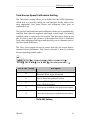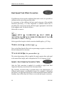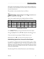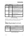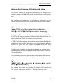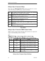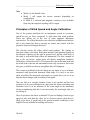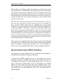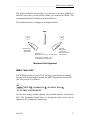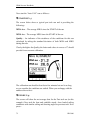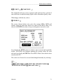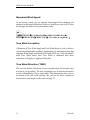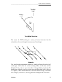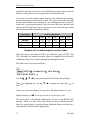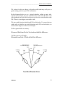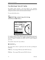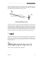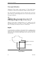
1
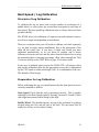
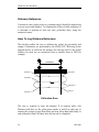
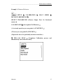
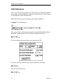
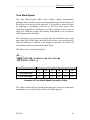
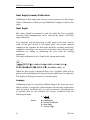
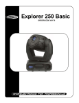
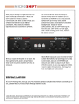
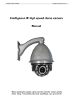
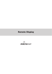
H3000 Owners Handbook________________________________________________________________________ CALIBRATION INTRODUCTION This section describes the calibration of your H3000 System via the GFD. Every care must be taken when undertaking any Calibration Procedure to ensure that the H3000 System is calibrated accurately and correctly. Incorrect calibration could lead to incorrect navigational information and possibly placing the yacht into danger. There are four sensor inputs to your system that are fundamental to its integrated approach - Boat Speed, Compass Heading, Measured Wind Angle and Measured Wind Speed. Without these basic inputs you cannot have the more important values of true wind speed and direction and velocity made good, which are calculated from them. As an absolute minimum your system should measure these four parameters. There are many really useful additional values that the H3000 allows you to measure, but they are not essential to the system's primary function. Nevertheless, these will need to be calibrated as well, but we shall deal with them separately, after we have calibrated the primary functions. On any yacht after the launch, the calibration of the sensors should have the same priority as making sure that the sails fit. It is crucial to keep a full record of the process. Appendix 1 contains calibration tables for this purpose. 54 HB-3000 _________________________________________________________ H3000 Owners Handbook Boat Speed / Log Calibration Principle of Log Calibration To calibrate the log we must work out the number of revolutions of a paddle wheel, or sonic pulses per second that correspond to each knot of boat speed. The boat speed/log calibration value is always shown as Hertz per knot (Hz/Kt) The H3000 allows for calibration of separate port and starboard sensors, as well as a single unit depending on installation. There are occasions when you will need to calibrate each tack separately e.g. for dual or single sensor installations, due to the placement of the units off the centre line. If you have a single unit which you have calibrated automatically, as we are about to explain, and it shows differences between one tack and the other, then the solution lies in using the manual method of entering percentage offset values through the Tack Correction facility on the GFD. Refer to page 59 for more detail. In the case of multiple speed sensors the H3000 CPU will always select and use the calibration value for the appropriate sensor; this is determined by the CPU based on either wind angle, heel or a combination of the two. The default is Wind Angle. Preparation for Log Calibration Before calibrating the log you should ensure that the boat speed sensor is correctly installed as follows: Sonic Speed: Check that the unit is operating correctly. This is usually indicated by the Boat Speed typically showing between 0.10 and 0.30 kts with slight movements whilst sitting at the dock. Paddle Wheel: The moulded arrows on top of the unit must be pointing forward along the fore and aft line of the hull. The unit must also be totally free of any weed or other fouling. HB-3000 55 H3000 Owners Handbook________________________________________________________________________ Distance Reference Consecutive runs, under power at a constant speed, should be made along a given course and distance. To eliminate the effect of tidal conditions, it is advisable to perform at least two runs, preferably three, along the measured course. How To Log Distance Reference This facility enables the user to calibrate the yacht's log accurately and simply. Calculations are performed by the H3000 CPU. Referring to the diagram below, A and B are the markers for each run and X is the actual distance for each run as ascertained from a suitable chart or GPS for example. A Cal Distance X Start Run 1 B Stop Run 1 Stop Run 2 Start Run 2 End Cal Start Run 3 Calibration Runs The user is required to enter the distance X in nautical miles (Cal Distance) and then, as the yacht passes marks A and B on each run, to instruct the system to start (Start Run) and stop (Stop Run) and finally to end calibration (End Cal Runs) after the last run is completed. 56 HB-3000 _________________________________________________________ H3000 Owners Handbook Example 1: Distance Reference SETUP X CALIBRATION DISTANCE REFERENCE X X BOAT SPEED X SELECT TRANSDUCER (Choose: Single, Port. Or Starboard sensor) CAL DISTANCE X (Set required Cal Distance) ( At a steady speed as you cross point A ) START RUN ( Then as you cross point B ) STOP RUN ( Repeat the above for preferably two more runs then ) T END CAL RUNS (Completes Calibration process and automatically stores the new value) HB-3000 57 H3000 Owners Handbook________________________________________________________________________ SOG Reference This is an Auto Cal facility that uses SOG from your GPS and compares the average of this against the average boat speed from the speed sensor for the duration of the calibration run. Note: This will only work accurately in non-tidal conditions. Example 2: SOG Reference SETUP X CALIBRATION X BOAT SPEED X SOG REFERENCE X The screen below will be shown giving the current SOG and Boat Speed. Maintain a steady speed for a few minutes if possible then press:T ACCEPT The new calibration value will now be stored in the CPU. The above can be repeated at this stage if required by selecting:T START Then at the end of the run:T ACCEPT 58 HB-3000 _________________________________________________________ H3000 Owners Handbook Tack Source Speed Calibration Setting The Tack Source setting allows you to define how the H3000 determines which tack it is presently sailing on, and therefore decide which is the most appropriate boat speed sensor and calibration value (port or starboard) to use. The port and starboard boat speed calibration values can be automatically switched from either the apparent wind angle or heel angle if a suitably installed sensor is connected to the system. The tack source function can also be used to force the system to select either Port Tack or Starboard Tack when calibrating boat speed and thus help you to eliminate tack-totack boat speed differences. The Force Tack options are used to ensure that only one sensor input is measured during calibration. Tack Source selection is done by entering the corresponding number under:- SETUP X CALIBRATION X OTHER CALIBRATION X WIND X TRUE DIR X TACK SRC X (Set value as in table ) TACK SRC Setting Description 0 Tack source uses heel as preference upwind and Measured Wind Angle downwind 1 Heel is always the preferred source. 2 Measured Wind Angle is always the preferred source (Default setting). 3 Force tack to starboard (uses port sensor input) 4 Force tack to port (uses starboard sensor input) TACK SRC Setting HB-3000 59 H3000 Owners Handbook________________________________________________________________________ Boat Speed Tack Offset Correction If a difference in boat speed is indicated from tack to tack, it is possible to calibrate out the error using an offset table. It is necessary to first calibrate the boat speed using one of the methods described previously, it is then important to establish which tack is providing the correct boat speed, and then apply appropriate corrections to the opposite tack. Do this as follows:Select tack to correct:- SETUP X CALIBRATION X BOAT SPEED X ADVANCED CALS X TACK CORRECTION X SELECT TACK X ( Set value 0 = Stbd, 1 = Port ) Select typical heel angle at which correction should apply e.g. 10º deg. T HEEL ANGLE X ( Set Heel Angle ) Now set the Boat Speed offset value as percentage, negative to reduce for this tack and positive to increase. T TACK OFFSET X ( Set percent offset ) The entered percentage offset is applied for angles greater than, and equal to the entered heel angle, and is interpolated to 0% at 0 degrees of heel. Speed / Heel Linearity Correction Table After the Tack correction is applied it is possible to apply both Heel Angle and Linearity corrections to the boat speed data. The Linearity correction table is provided due to the characteristics of different speed sensors, a paddlewheel sensor (for example) is inherently non-linear so at high boat speeds due to their mechanical nature and hull boundary layer effects they are likely to over-read and require correction. 60 HB-3000 _________________________________________________________ H3000 Owners Handbook Heel Angle corrections apply to all types of sensor and are actually due to the change in water flow patterns over the surface of the hull rather than the sensor characteristics. The procedure to enter correction values is as follows: SETUP X CALIBRATION X BOAT SPEED X ADVANCED CALS X HEEL CORRECTION TABLE X After a few seconds the table will be loaded and shows as follows:Heelº 0º 10º 20º 5 0.0 -0.2 -0.4 10 -2.0 -2.3 -3.9 Boat Speed (Knots) 15 20 -3.9 -6.0 -4.0 -6.5 -6.1 -8.5 25 -7.8 -9.6 -11.5 30 -9.3 -11.0 -13.3 Boat Speed Correction Use the X W T S keys to move around each of the cells to adjust Press to highlight the cell, use T S to adjust the value then to save. Values are entered as a percentage. All default values are zero. Repeated presses of W will escape left and exit the table entry mode. Substituting Speed Over Ground for Boat Speed It is possible to substitute Speed Over Ground (SOG) in place of Boat Speed for use throughout the system. This may be desirable for certain applications such as fast planning mono and multi-hulls where the speed sensor may spend periods of time out of the water. It could also be used in the case of sensor failure. Note that using SOG for calculated functions has some disadvantages: HB-3000 61 H3000 Owners Handbook________________________________________________________________________ SOG is not the same as Boat Speed as it is referenced to the ground rather than the water, which may be moving due to tidal flows and currents, so SOG will not allow calculation of Tide. Calculation of Wind data via SOG will actually give Ground Wind data, so will appear inaccurate in strong tidal conditions. SOG is also updated less frequently on the network. The speed source setting is entered under: SETUP X COMMISSION X USE SOG AS SPEED INPUT X ( Set value 0 = Normal speed sensor, 1 = SOG ) Pulse2 Boat Speed Input The H3000 is able to display boat speed-readings from a second boat speed sensor connected to the CPU. The function PULSE2 can be renamed by selecting one of the pre-defined functions. This is done by entering the corresponding number under: SETUP X CALIBRATION X OTHER CALIBRATION X SPEED X PULSE2 X TYPE X ( Set value as in table ) 62 HB-3000 _________________________________________________________ H3000 Owners Handbook TYPE Setting Function Text Shown Notes 0 PULSE2 Default setting. The display will show the input in Hz if present. STBD BS The second boat speed sensor is declared as the STBD sensor under the SPEED menu. When on port tack, the Boat Speed is derived form the STBD sensor. PORT BS The second boat speed sensor is declared as PORT under the SPEED menu. When on stbd tack, the Boat Speed is derived form the PORT sensor. 1 2 The primary boat speed sensor is BOAT SPD completely replaced by the second boat speed sensor. 3 Pulse2 TYPE Setting Additionally, it is possible to configure the H3000 to use an external speed source and disable the boat speed sensor inputs connected to the CPU. This is done by entering the corresponding number under: SETUP X CALIBRATION X OTHER CALIBRATION X SPEED X PULSE2 X EXT.BSPD X ( Set value as in table ) CAL VAL 2 Setting Description 0 Default setting. Uses the boat speed sensor(s) connected to the CPU. 1 Uses an external boat speed source. For example, a paddlewheel sensor connected to a pilot computer or NMEA boat speed decoded by the CPU. Pulse2 EXT.BSPD Setting HB-3000 63 H3000 Owners Handbook________________________________________________________________________ Compass Calibration B&G's Autoswing compasses contain software that allows them to record the magnetic fields in the yacht that are causing deviation errors. It calculates the corrections when the COMP CAL function is started and provided the following conditions are met: The 360q turn - Halcyon 2000 and Halcyon Gyro Stabilised Compass is completed in the same direction. The rate of change of heading does not exceed 3°/s; i.e. the turn should take about 3 minutes to complete. The rate of change of heading must not fall below 0.2 of a degree per second during the 360° turn, i.e. the turn must not take longer than 12 minutes. The rate of change in heading is reasonably constant. The compass is installed in a location a safe distance from magnetic interference such as iron keels, engines, loudspeakers etc. Consideration should also be given to electrical cables which may carry high currents (e.g. large motors). The compass is installed in a location as close to the centreline of the boat as possible. Avoid areas such as the fore peak and the sides of the hull where the effects of pitch and roll are at their greatest. On steel hulled vessels, the compass will need to be installed above decks away from the effects of the hull. Heading Source Selection The H3000 System can accept heading data from a variety of different sources. These different sources are known as Nodes and allow the system to identify which heading devices are connected to the system. The list below shows the various sources of heading available with its respective address node: 64 HB-3000 _________________________________________________________ H3000 Owners Handbook Device CPU (NMEA input) Halcyon Processor (“Halcyon Gyro” input) Halcyon Processor (NMEA input) Halcyon 2000 Compass ACP Pilot (direct “Halcyon Gyro” input) NMEA Input to NMEA FFD Node 5 15 15 16 18 96, 97… Heading Source Setup the required heading node by following the procedure below: SETUP X COMMISSION X HEADING X (Set value as in table above) Note x Hydra and Hercules Pilots will also require the Heading Node to be set to your desired choice. Refer to the relevant user manual for further information. x 20/20 displays will require Heading to be re-selected following Heading node selection. Simply re-select this function. Refer to configuring REMOTE UNITS section earlier in this manual. Halcyon 2000 Compass Calibration Procedure (Auto Swing) Check for any magnetic devices placed near the compass, especially ones that are out of their normal places. On a calm day select a stretch of open water with little traffic (so you will not have to take avoiding action which would affect the calibration). The flatter the water and the less the wind the easier it will be to meet the conditions for calibration. Check for and avoid sailing close to any large steel structures nearby, that may cause additional, erratic deviations. HB-3000 65 H3000 Owners Handbook________________________________________________________________________ Now select:- SETUP X COMMISSION X START COMPASS SWING X The display will now show the degrees of turn completed so far. When the full 360 deg turn has completed within the limits described earlier, the display should say “PASS” to indicate a successful swing. A “FAIL” indication suggest that the turn was not completed within the guidelines or quite possibly that there is too great a magnetic influence close to the sensor. This will require investigation before the swing process is retried. Now the swing is complete its important to eliminate any constant error in heading due to the physical alignment of the sensor relative to the fore / aft line of the boat. This is normally checked for by using shore-based transits, once the error is known it can be eliminated by entering the value into the system under: SETUP X CALIBRATION X HEADING VALUE X (Enter new value) X SET OFFSET For example, the compass was reading 320º and it should read 316º, then the value to enter would be –4º from the current set value Note x The first time the system is switched on, or after a system reset, the Heading will alternate with CAL. This is to indicate to the user that the compass must be calibrated. This will disappear after the compass has been swung correctly. 66 HB-3000 _________________________________________________________ H3000 Owners Handbook Halcyon Gyro Compass Calibration and Setup This section describes the setup and calibration of the Halcyon Gyro compass connected to the H3000 system via the Halcyon Gyro Processor unit. The conditions and preparations for performing an Auto swing are the same as described in the previous section for the Halcyon 2000 Compass. Once ready to start the swing select:- SETUP X CALIBRATION X OTHER CALIBRATION X MISC X HALCYON X START X (Set value to 1 starts swing) The display will now show the degrees of turn completed so far. When the full 360 deg turn has completed within the limits described earlier, the display should say “PASS” to indicate a successful swing. A “FAIL” indication suggest that the turn was not completed within the guidelines or quite possibly that there is too great a magnetic influence close to the sensor. This will require investigation before the swing process is retried. Now the swing is complete its important to eliminate any constant error in heading due to the physical alignment of the sensor relative to the fore / aft line of the boat. This is normally checked for by using shore-based transits, once the error is known it can be eliminated by entering the value into the system under: SETUP X CALIBRATION X HEADING X SET OFFSET VALUE X (Enter new value) For example, the compass was reading 320 degrees and it should read 316, then the value to enter would be –4 from the current set value HB-3000 67 H3000 Owners Handbook________________________________________________________________________ Halcyon Gyro Processor Setup Data under the MISC X HALCYON function describes the current mode of the Halcyon Gyro Processor, and are as follows: No heading detected from either a Halcyon Gyro Stabilised Compass sensor or a B&G system compass Receiving data from Halcyon Gyro Stabilised Compass or GYRO NMEA input to Halcyon Gyro Processor Receiving data from a B&G system compass or NMEA input SYS to NMEA FFD or performance processor OFF PASS FAIL xxxº Calibration swing is complete Calibration swing failed and the compass needs to be recalibrated Number of degrees turned during calibration swing, indicates calibration swing in progress Gyro Setup Halcyon Gyro Processor NMEA output setup NMEA sentence output settings determine what sentences are output with respect to which heading source is available. SETUP X CALIBRATION X OTHER CALIBRATION X MISC X HALCYON X NMEA MDE X Set value as table below Mode Output Details from Halcyon Gyro Stabilised Compass or HDT 0 NMEA input to Halcyon Gyro Processor from Halcyon Gyro Stabilised Compass or 1 HDM NMEA input to Halcyon Gyro Processor from Halcyon Gyro Stabilised Compass or 2 HDG NMEA input to Halcyon Gyro Processor from a B&G system [compass or NMEA 3 HDM/HDT input to FFD] from a B&G system [compass or NMEA 4 HDG input to FFD] Halcyon Gyro Compass Output Settings 68 HB-3000 _________________________________________________________ H3000 Owners Handbook Note x Mode 0 is the default value x Mode 3 will output the correct sentence depending on configuration. x If Mode 4 is selected and magnetic variation is not available then only the magnetic heading will be output. Principles of Wind Speed and Angle Calibration One of the greatest problems for an instrument system to overcome, which has not yet been conquered, is wind shear and wind gradient. These two effects are at the root of some apparent instrument inaccuracies. The effects themselves are relatively straightforward and are due to the simple fact that as moving air comes into contact with the ground it slows and changes direction. The slowing creates the effect called wind gradient. The change in direction creates wind shear. Both shear and the wind gradient depend on the amount of mixing of the wind at ground level and the wind aloft; if the wind is well mixed both effects are minimised. The best example of this is the sea breeze, which starts off almost completely unmixed. Differences of direction of 40º-50º between the wind at the mast head and the wind at the water are not uncommon in an early sea-breeze, but as the day goes on and the sea-breeze strengthens this will disappear. This creates a problem for the two things we are about to try to calibrate, measured wind speed and measured wind angle. It is easy to see how shear can affect the measured wind angle; no sooner have you set it up than the shear changes and everything is out again. This can lead to a circular situation if one is not careful, and the best solution is to do your calibration on a day when the shear is minimal, and thereafter leave it as an indicator of the wind angle at the masthead, always remembering that this is not necessarily the wind angle that you are sailing at. How do you know the shear is minimal? If you are finding it easier to get speed on one tack than the other for no obvious reasons, then there is likely to be shear. A good look at the general weather conditions is also helpful. Do not calibrate in building sea breezes. HB-3000 69 H3000 Owners Handbook________________________________________________________________________ Wind gradient is the biggest culprit for getting true wind speeds accused of gross inaccuracy. The problem is that most people use the wind speed as a measure of the pressure, which it is not. It is a measure of the wind speed at the top of the mast, and that is all. If it is 12 knots at the top of the mast and only 4 at the water, then the breeze will feel a lot softer, and provide less power for the rig than if the breeze is twelve knots all the way down to the water. There are other signs that can help get a feel for the pressure on the rig. One of the most important of these is the heel angle; it is no bad thing to have an idea of how much heel you normally have in any given windspeed. Target boat speeds can also provide valuable information as to the wind gradient. The target is read from a polar table which only knows about one average wind condition, it does not know if the wind has a strong gradient or none at all. So next time you are having trouble reaching the target speeds, think about the wind gradient and whether or not it is a soft or heavy breeze, and use the input to help sail the boat. The information from the instruments is generally useful - it just needs rather more interpreting than it sometimes gets. This is why we recommend that the last thing you touch is the Measured Wind Speed. It is calibrated in the factory where wind tunnel calibrated units are available, and apparent inaccuracies are 99% attributable to effects such as wind gradient, rather than to a basic calibration problem. Measured Wind Angle (MWA) Calibration This provides an offset calibration for any mechanical misalignment of the Mast Head Unit (MHU) at the top of the mast. To discover the MWA alignment error we can employ one of two techniques. The first is simply to go head to wind and read the value of the Measured Wind Angle. If it reads anything other than 0, you have an error. If the error is greater than 0 (up to 180 degrees), you should subtract the error from 0 and enter this as the calibration value. So if when you go head to wind the measured wind angle reads 4 degrees, then you should enter -4 as the calibration value. If it is less than 0 then the opposite applies. 70 HB-3000 _________________________________________________________ H3000 Owners Handbook The before method is not actually very accurate as its quite difficult to hold the boat head to wind steadily whilst you monitor the MWA. The recommended method is therefore described below:This method involves a sailing trial as depicted below. WIND 27º 33º Starboard Tack Sails sheeted Close hauled Difference = 6º Masthead unit error 6º / 2 = 3º (CAL value) Port Tack Sails sheeted Close hauled Exactly the same as starboard tack If port tack is low subtract 003º If starboard tack is low add 003º Masthead Unit Alignment MWA “Auto CAL” The H3000 provides an “Auto CAL” facility for use during this sailing trial and will automatically calculate the MHU alignment correction for you. The process is as follows:- SETUP X CALIBRATION X APPARENT WIND X AUTO MHU ALIGNEMENT Get the boat sailing steadily upwind, close hauled with the sails sheeted fully. The helmsman should focus on steering the boat to the sails as opposed to the instruments at this stage. HB-3000 71 H3000 Owners Handbook________________________________________________________________________ Now start the “Auto CAL” run as follows:T START RUN The screen below shows a typical port tack run and is providing the following:MWA Ave – The average MWA since the START of the run MWS Ave – The average MWS since the START of the run Quality – An indicator of the steadiness of the conditions for this run calculated by taking the standard deviation of both MWA and MWS during that run. Clearly the higher the Quality the better and values in excess of 7 should provide for an accurate calibration. The calibration run should at least last a few minutes but can be as long as you consider the conditions are settled. When you are happy with the numbers then select:T END RUN The screen will show the net average data for the Port tack run (in this example) Now tack the boat and establish steady, close hauled sailing conditions with similar sailing and sheeting angles as previous tack. Now press:- 72 HB-3000 _________________________________________________________ H3000 Owners Handbook T T NEXT T START RUN The starboard tack run is now in progress and again sail for a period of time sufficient to establish steady figures with a reasonable Quality value. When happy with this run, select:T END RUN The screen (shown below) now gives the average MWA, MWS and Quality values for both tacks and a new value for the MHU offset. You can now ACCEPT this value or keep on doing more runs tack to tack (by selecting the NEXT option) to achieve more accurate and repeatable results. The H3000 will continue updating the average values for each tack until you finally ACCEPT the New MHU Offset value which is then stored in the CPU. This value can of course be accessed and changed manually by selecting:- SETUP X CALIBRATION X APPARENT WIND X WIND ANGLE OFFSET X (Enter new value) HB-3000 73 H3000 Owners Handbook________________________________________________________________________ Measured Wind Speed As previously stated you are strongly discouraged from changing the measured wind speed calibration. However, should you need to do it, then the changes are made in the system menu under: SETUP X CALIBRATION X OTHER CALIBRATION X WIND X MEAS W/S X MHU CAL X ( Set value as required ) True Wind Correction Calibration of True Wind Angle and True Wind Speed is vital to achieve consistent and repeatable readings. Furthermore, its important to note that Apparent Wind Angle and Speed (AWA and AWS) are “back calculated” from True Wind, hence once True Wind is calibrated then these corrections will apply to Apparent Wind also. True Wind Direction (TWD) The need for further calibration of true wind direction will become clear as soon as you go sailing. The true wind might vary in direction from tack to tack, independently of any wind shifts. This phenomenon has come to be known as the true wind 'tacking'. We can see the direct connection between true wind angle and direction on page 75. 74 HB-3000 _________________________________________________________ H3000 Owners Handbook True Wind Direction = 280º Heading = 240º TWA = 40º True Wind Direction The reason for TWD tacking is a variety of errors that enter into the calculation of true wind angle from measured wind angle. Upwash The wind that the instruments measure is actually deflected from the 'real' wind angle. Add to this the various twisting effects of the mast and the Masthead Unit, and we get some idea of the problems involved. The hardest part is that it is easy to see the true wind direction 'tack' as little as 2-3 degrees, which would mean the correction factors being as accurate as 0.5 degree, or about 1%. For any particular windspeed the correction HB-3000 75 H3000 Owners Handbook________________________________________________________________________ needed for all these errors have to be different from day to day, not least because of the problems of wind gradient we discussed earlier. As we have seen the problem stems from the true wind direction 'tacking' as the boat manoeuvres from tack to tack. We need to know the error that the true wind suffers in any manoeuvre, be it tacking upwind, a reach-toreach tack, or gybing downwind. Once you know the error, and the wind speed you had at the time, then we can enter it as a correction into a table of corrections similar to that shown below Wind Angle Upwind Reaching Downwind 5 -7.0 -2.0 4.0 10 -3.0 -1.0 3.0 True Wind Speed 15 20 -2.5 4.5 0.0 1.0 1.0 -1.0 25 6.5 1.0 -1.0 30 8 1.5 -2.0 Example of True Wind Angle Correction Table. The above show corrections to TWA at 6 different values of TWS. The CPU calculates the actual correction value to be applied for the specific conditions using a 2 way linear interpolation through the table. This table can be accessed as follows:- SETUP X CALIBRATION X TRUE WIND X TRUE WIND TABLE Use the X W T S keys to move around each of the cells to adjust Press to highlight the cell, use T S to adjust the value then to save. Values are entered as degrees of correction. All default values are zero. Repeated presses of W will escape left and exit the table entry mode. The above table is by default initialised to all zero in the H3000 CPU memory. There is in fact a base table which can be pre-initialised and is based on some typical correction figures obtained during sea trials on a conventional, 45ft, fractional rigged yacht. 76 HB-3000 _________________________________________________________ H3000 Owners Handbook The values for this are shown in the above table and may well prove a good starting point for your TWA calibration. In the diagram below we see a typical situation, sailing on port tack, upwind, in ten knots, the true wind direction reads 210. We tack over onto starboard and settle the boat down, now the true wind direction reads 200. There is a ten-degree error tack to tack. The true wind direction should read 205 on both tacks. To correct the true wind angle so that the true wind direction reads 205 on both tacks, we need to add 5 degrees to the true wind angle. So for a general rule we can say: If you are lifted from Tack to Tack subtract half the difference. And the converse will apply: If headed from Tack to Tack add half the difference. Port Tack True Wind Direction 210º Starboard Tack True Wind Direction 200º 10º Heading = 160º TWA 40º TWA 40º Heading = 250º True Wind Direction Error HB-3000 77 H3000 Owners Handbook________________________________________________________________________ True Wind Angle “Auto Cal” facility The H3000 system provides a neat and simple to use, automatic calibration facility to aid the process. It takes all the hard work out of noting down numbers and the associated mental arithmetic . To access this facility select:- SETUP X CALIBRATION X TRUE WIND X AUTO TWA CORRECTION It is usual to start the TWA calibration process by setting the boat up to do a number of tacks upwind in as steady conditions as possible. The process is similar in concept to the MWA Auto Cal facility explained previously. Now start the “Auto CAL” run as follows:T START RUN The screen above shows a typical port tack run and is providing the following:TWD Ave – The average TWD since the START of the run TWS Ave – The average TWS since the START of the run 78 HB-3000 _________________________________________________________ H3000 Owners Handbook Quality – An indicator of the steadiness of the conditions for this run calculated by taking the standard deviation of both TWA and TWS during that run. Clearly the higher the Quality the better and values in excess of 7 should provide for an accurate calibration. The three dotted lines in the boat graphic indicate the three calibration points of sailing, close hauled (TWA = 45), Reaching (TWA = 90) and Downwind (TWA = 165). The arrow relative to boat graphic indicates the current TWA The calibration run should at least last a few minutes but can be as long as you consider the conditions are settled. When you are happy with the numbers then select:T END RUN The screen will show the net average data for the Port tack run (in this example) Now tack the boat and establish steady, upwind sailing conditions again. Now press:T T NEXT T START RUN The starboard tack run is now in progress and again sail for a period of time sufficient to establish steady figures with a reasonable Quality value. When happy with this run, select:T END RUN The screen (shown below) now gives the average TWD and TWS and Quality values for both tacks and calculated value for TWA correction for Upwind at the current TWS. You can now ACCEPT this value or keep on doing more runs tack to tack (by selecting the NEXT option) to achieve more accurate and repeatable results. The H3000 will continue updating the average values for each tack until you finally ACCEPT the New TWA correction value which is then stored in the CPU. HB-3000 79 H3000 Owners Handbook________________________________________________________________________ The CPU stores the calculated values in the TWA Correction table as described above. It will do so initially by rounding up / down the average TWS value for the run to the nearest 5 knot TWS increment in the table. Once the Upwind sector is calibrated for the current TWS band then repeat the TWA Auto Cal process for Reaching tack to tack and then gybing downwind. The process of START, END RUN, NEXT etc. is exactly the same for each point of sailing. As additional TWA cal runs are performed in different TWS ranges, so the table will become further populated. Once two or three TWS ranges are done then the CPU will attempt to extrapolate the data across further wind speed and wind angle bands. This whole process of TWA calibration can and should be a regular process especially pre start of a race. The TWA Auto Cal facility is quick and simple and will help to “fine tune” the numbers. Finally, the most important thing is to record all these entries in the Calibration Charts provided in Appendix 1. 80 HB-3000 _________________________________________________________ H3000 Owners Handbook True Wind Speed The True Wind Speed suffers from another, mainly aerodynamic, problem, where it tends to over-read downwind because of acceleration of the airflow over the top of the main sail. It is possible to correct for this by applying a downwind correction to the true wind speed. This correction is applied at 165 degrees in a Hydra system, or at the user set angle in a *Hercules system, and linearly interpolated to zero correction at 90 degrees true wind angle. The routine here is to bear away quickly from close-hauled to your usual downwind True Wind Angle and watch the increase in true wind speed. Then the difference is entered as the negative correction. The table will look similar to the one shown in the table below. This table can be accessed as follows:- SETUP X CALIBRATION X TRUE WIND X TRUE WIND TABLE Wind Angle Correction (kt) Correction angle* 5 0 165 True Wind Speed 10 15 20 25 0 0 0 0 165 165 165 165 30 0 165 Example of True Wind Speed Correction Table The values in each cell are entered in the same way as the true wind angle corrections. It is crucial to keep a full record of the process. HB-3000 81 H3000 Owners Handbook________________________________________________________________________ Heel Angle/Leeway Calibration Calibration of Heel Angle and Leeway is only necessary if a Heel Angle Sensor (Clinometer) or Halcyon Gyro-Stabilised Compass is fitted to the yacht. Heel Angle The sensor should be mounted to read zero when the boat is upright. However, small misalignments can be corrected by means of the heel angle calibration. On a calm day with the boat lying at slack warps in the dock, head to wind, all the gear stowed in its normal place, and anyone onboard standing on the centreline the heel angle should be recorded, under these conditions it should be zero, any error can be taken out by the heel angle calibration, by adding or subtracting the error from the existing calibration. Heel angle calibration is to be found in the system menu under: SETUP X CALIBRATION X OTHER CALIBRATION X PERFORM X HEEL X OFFSET X ( Set Offset value ) When the Heel Angle is displayed there is an H symbol which will be placed on left indicating heel to port and on the right for heel to starboard. The display will always be shown to 1 decimal point Leeway Calibrating leeway is a notoriously difficult thing to do; it may be easier, and as accurate, to consult the yachts designer who may have a theoretical value for leeway coefficient, as it is to try to measure it. Should that not be possible then we can calculate the Leeway coefficient from the following formula: Where, 82 L = KxH Bs x Bs Bs = Boat Speed K = Leeway Coefficient H = Heel Angle L = Leeway Angle HB-3000 _________________________________________________________ H3000 Owners Handbook K then is the constant that needs to be entered, and to establish a value for leeway coefficient we need to measure the leeway angle at a particular heel angle and boat speed shown in Fig 11 below. Hea di ng Course Leeway Angle He a ding Back Bearing N Markers xº - 180 º Leeway Angle Measurement The idea is to sail on a steady course and drop markers* over the stern at regular intervals, the angle between them and the centreline of the yacht is measured with a hand-bearing compass, and hence leeway angle is measured. Whilst this is happening the boat speed and heel angle should be noted at intervals and an average calculated. These values can then be used to calculate the leeway coefficient from the following expression:- K = L x Bs x Bs H Obviously the flatter the water and the steadier the breeze the more likely this is to be successful, but even in perfect conditions it is difficult, to say the least. Once you have the leeway coefficient 'K' then it is entered into the system under: SETUP X CALIBRATION X OTHER CALIBRATION X NAVIGATE X LEEWAY X CAL VAL1 X ( Set value K ) *Please collect your markers after calibration! HB-3000 83 H3000 Owners Handbook________________________________________________________________________ Trim angle Calibration Calibration of Trim Angle is only necessary if a Trim Angle Sensor (Clinometer) or Halcyon Gyro-Stabilised Compass is fitted to the yacht. The sensor should be mounted to read zero when the boat is level fore and aft. However, small misalignments can be corrected by means of the Trim angle calibration. SETUP X CALIBRATION X OTHER CALIBRATION X PERFORM X TRIM X OFFSET X ( Set Offset value ) When the Trim Angle is displayed there is a U symbol on the left indicating that the bow is up, while a d will be shown indicating bow down. The display will always be shown to 1 decimal point Depth A typical transducer installation is through the hull at a suitable position between the water line and the bottom of the keel. A DATUM (offset value) can be set, such that the depth display refers to either the water line or the keel line. +VE DATUM for WATERLINE (0.0) -VE DATUM for KEEL Depth Datum 84 HB-3000 _________________________________________________________ H3000 Owners Handbook The datum is entered under: SETUP X CALIBRATION X DEPTH DATUM X ( Set Datum value ) AFT Depth The H3000 has the facility to display NMEA depth data from an auxiliary depth source. Any NMEA depth information input into the NMEA port on the H3000 CPU is displayed on the system as AFT DEPTH. A depth datum offset is available for the AFT DEPTH function. The datum is entered under: SETUP X CALIBRATION X OTHER CALIBRATION X DEPTH X AFT DEPTH X DATUM ( Set Datum value ) Additionally, it is possible to re-name the function AFT DEPTH by selecting one of the pre-defined function names. This is done by entering the corresponding number under: SETUP X CALIBRATION X OTHER CALIBRATION X DEPTH X AFT DEPTH X TEXT SEL (Set value as table below) TEXT SELect Setting Function Text Shown 0 1 2 3 4 5 AFT DPTH FWD DPTH MID DPTH PORT DEP STBD DEP DEPTH 2 Cal Val 2 Setting – Depth HB-3000 85 H3000 Owners Handbook________________________________________________________________________ Battery Volts The H3000 monitors the yacht's battery supply and can be shown on any display, giving a reading in volts. This is calibrated by the manufacturer and should not require adjustment except in exceptional circumstances or after a system reset. If it is necessary to calibrate this function a suitable voltmeter is required. The calibration value is found in the menu under: SETUP X CALIBRATION X OTHER CALIBRATION X MOTOR X VOLTS X CAL VAL 1 X ( Set value as explained below) Using the independent voltmeter, measure the battery supply at the PWR connector located under the bottom cover of the H3000 CPU unit. Alter CAL VAL1 to match the value from the voltmeter. Sea Temperature If a suitable temperature sensor is fitted, the H3000 will monitor the current sea temperature. The standard B&G paddle-wheel has a sensor incorporated within it, in this case no further action is required. If the sensor is a totally independent fitting (B&G part no. 224-00-065) then it is necessary to change the sensor selection value. This value is found in: SETUP X CALIBRATION X OTHER CALIBRATION X TEMP X SEA TEMP XSENSOR X(Set value as explained below) The default selection value is 1, for the independent sensor we need to change to 2. 86 HB-3000 _________________________________________________________ H3000 Owners Handbook Sea Temperature Offset Calibration To calibrate SEA TEMP proceed as follows: SETUP X CALIBRATION X OTHER CALIBRATION X TEMP X SEA TEMP X OFFSET X ( Set value as explained below ) This calibration can be carried out on either SEA TEMP ºC or SEA TEMP ºF The offset value is automatically converted so that both degrees C and F are adjusted correctly. HB-3000 87