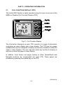
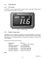
1
USER MANUAL
Premier Way, Abbey Park
Romsey, Hampshire, S051 9DH
England
Tel: (+44) 01794 518448
Fax: (+44) 01794 518077
www.BandG.com
© Brookes & Gatehouse Ltd. 2000
HB-0844-04
The copyright of this Manual is the property of Brookes & Gatehouse Ltd.
HB-0844-04
USER MANUAL
Amendment No. 04 August 2001
CONTENTS
Product Liability and Safety Warnings
Record of Amendments
PART 1
-
PART 2
-
OPERATING INFORMATION
PART 3
-
CALIBRATION
PART 4
-
INSTALLATION INFORMATION
PART 5
-
OPTIONS
PART 6
-
DIAGNOSTIC DATA
APPENDIX 1
INTRODUCTION
CALIBRATION DATA
HB-0844-04
PRODUCT LIABILITY AND SAFETY WARNINGS
PRODUCT LIABILITY
Brookes and Gatehouse Limited accept no responsibility for the use and/or
operation of this equipment. It is the user’s responsibility to ensure that under all
circumstances the equipment is used for the purposes for which it has been
designed.
WARNING - ELECTRICAL HAZARD
This equipment uses high voltage electrical power. Contact with high voltages may
result in injury and/or loss of life.
WARNING - CALIBRATION
The safe operation of this equipment is dependent on accurate and correct
calibration. Incorrect calibration of this equipment may lead to false and inaccurate
navigational readings placing the yacht into danger.
WARNING - NAVIGATION HAZARD
The Hydra 2000 is an Electronic Navigation System and is designed to assist in the
navigation of your yacht. It is not designed to totally replace conventional navigation
procedures and precautions and all necessary precautions should be taken to
ensure that the yacht is not placed into danger.
CAUTION
This equipment is designed for use with a power supply source of 12v dc. The
application of any other power supply may result in permanent damage to the
equipment.
HB-0844-04
RECORD OF AMENDMENTS
Date
Amendment
Number
Description
Signature
HB-0844-04
PART 1 - INTRODUCTION
CONTENTS
Para
Page
1.1
SYSTEM DESCRIPTION
1-3
1.2
1.2.1
1.2.2
1.2.3
PROCESSORS
Main Processor Unit
Expansion Unit
Halcyon Gyro Processor
1-3
1-3
1-4
1-4
1.3
1.3.1
1.3.2
1.3.3
1.3.4
1.3.5
1.3.6
1.3.7
1.3.8
SENSORS
Masthead Unit
Paddle Wheel
Sonic Speed Unit
Depth Sensor
Super Halcyon 3 Fluxgate Compass
Halcyon 2000 Compass
Halcyon Gyro Stabilised Compass
Additional Sensors
1-4
1-4
1-5
1-5
1-5
1-5
1-5
1-5
1-6
1.4
1.4.1
1.4.2
1.4.3
1.4.4
1.4.5
1.4.6
DISPLAYS
NMEA Full Function Display (FFD)
Standard FFD
20/20 Display
40/40 Display
Analogue Indicators
Halcyon Display
1-6
1-6
1-7
1-7
1-7
1-7
1-7
1.5
CALIBRATION
1-8
1.6
DAMPING
1-8
1.7
MENU STRUCTURE
1-8
ILLUSTRATIONS
Fig No
1.1
Page
Typical Hydra 2000 System Block Diagram
1-2
TABLES
Table No
Page
HB-0844-04
1-1
1.1
1.2
Function Menu Choices
Operational Menu Choices
1-9
1-11
HB-0844-04
1-2
GPS Antenna
Unit
Mast Head
Unit
20/20
20/20
Mast
Halcyon Compass
Display
FFD
Hal cyon
000
Deck
GPS Plus
FFD
000
Chart Table
NMEA FFD
000
Hydra 2000
Main Processor
EP
Network
Hull
Additional Sensors
Sea and Air Temperature, Heel,
Trim, Barometric Pressure and Strain
Halcyon 2000
Compass
Depth
Sonic Speed Unit
Boat
Speed
Fig 1.1 - Typical Hydra 2000 System Block Diagram
HB-0844-04
1-3
PART 1 - INTRODUCTION
1.1
SYSTEM DESCRIPTION
The Hydra 2000 is a fully integrated instrumentation system that displays
information obtained from various sensors on a choice of displays
positioned throughout the yacht. Information is fed from the sensors to a
Main Processor. From the information gathered by the sensors the Main
Processor distributes information to the various displays via the Fastnet
cable. This allows it to carry out a wide range of functions including dead
reckoning, true wind speed and true wind direction, etc. These functions are
controlled from a Full Function Display (FFD).
A typical system is shown in Figure 1.1 - Typical Hydra 2000 System Block
Diagram.
1.2
PROCESSORS
1.2.1
Main Processor Unit
The Main Processor is the heart of the system and can be connected to
sensors that measure the following:
Boat Speed/Log
Depth
Sea Temperature
Air Temperature
Compass Heading
Apparent Wind Speed
Apparent Wind Angle
Ship's Supply Voltage
Heel Angle
Trim Angle
Mast Rotation
Barometric Pressure
Forestay Load
From this information the Main Processor Unit is then able to calculate the
following additional functions:
Average Boat Speed
Velocity Made Good (VMG) upwind/downwind
HB-0844-04
1-4
Resettable Log
Dead Reckoned Course and Distance
Leeway
Heading Corrected for Leeway (Course)
True Wind Speed
True Wind Angle
True Wind Direction
Heading on Next Tack or Gybe
Pressure Trend
In addition, the processor provides four outputs for analogue indicators. Any
one of eight different types of analogue indicator can be used on any one of
these outputs.
It also contains the battery backed memory that stores all the calibration,
damping and alarm settings whilst the power is OFF. These are adjustable
from any FFD.
1.2.2
Expansion Unit
The Expansion Unit allows a further four analogue indicators and a number of
additional sensors to be added to the system. Further details are given in
Part 5 - Options.
1.2.3
Halcyon Gyro Processor
The Halcyon Gyro Processor Unit is an interface between the Halcyon Gyro
Stabilised Compass and the B&G Fastnet Network. It also outputs NMEA
heading information for use with other marine instruments and AD10 for use
with Radar.
The Halcyon Gyro Processor accepts NMEA data from your position fixer for
magnetic variation information to allow display and output of True referenced
heading.
The Halcyon Gyro Processor can also be used as an interface to either
output NMEA heading and AD10 from a B&G system compass, or to accept
True heading NMEA information from a gyro compass to output and display
on a B&G system, along with AD10 and NMEA outputs.
Full details are given in Part 3 – Calibration.
1.3
SENSORS
HB-0844-04
1-5
1.3.1
Masthead Unit
The Masthead Unit senses apparent wind speed and wind angle. The unit is
light weight and sealed.
1.3.2
Paddle Wheel
The Paddle Wheel Speed Sensor is designed primarily for cruising yachts
and consists of a paddle wheel that protrudes through the hull via a housing.
So that the paddle wheel may be cleaned at regular intervals the housing is
provided with a flap valve that closes automatically when the unit is pulled
back into the yacht.
1.3.3
Sonic Speed Unit
The Sonic Speed Unit provides highly accurate and stable boat speed
measurement. It does not rely on mechanical moving parts that require
constant attention to protect them from weed, etc. The transducers are fitted
virtually flush with the hull, creating almost zero drag, and can be painted,
faired or anti-fouled.
1.3.4
Depth Sensor
This can either be a removable through-hull unit, or moulded in-hull for
reduced drag. The depth datum can be set to the waterline, the bottom of the
keel or from the transducer.
1.3.5
Super Halcyon 3 Fluxgate Compass
This fluxgate compass sensor is fully gimballed in a bath of oil, ensuring
accurate readings at all normal angles of heel and pitch. The unit features
automatic deviation correction, thus eliminating the need for expert compass
adjustment.
1.3.6
Halcyon 2000 Compass
The Halcyon 2000 Compass is a high performance electronic fluxgate
compass for use on both sailing and power craft. It is intended to be
connected to Hercules 2000, Hydra 2000 or HS 2000 instrument systems
through the B&G Fastnet Network.
HB-0844-04
1-6
The Halcyon 2000 Compass has the ability to ‘learn’ the magnetic effect of
the vessel on the compass and automatically apply deviation correction.
1.3.7
Halcyon Gyro Stabilised Compass
The Halcyon Gyro Stabilised Compass (HGSC) is a high performance, solid
state compass that provides the best available heading information through
the use of rate gyros to correct for the motion of your yacht. It also provides
high accuracy Heel and Trim. It interfaces to Hercules, Hydra and HS 2000
instruments via the Halcyon Gyro Processor that transmits this information to
the B&G Fastnet Network.
The HGSC is an easily calibrated compass that ‘learns’ the magnetic effects
of your vessel on the compass and automatically applies the deviation
correction.
1.3.8
Additional Sensors
Additional sensors provide either single inputs, or improve the accuracy of
other functions on the system and they are discussed in Part 5 - Options.
1.4
DISPLAYS
1.4.1
NMEA Full Function Display (FFD)
This is the standard system display and every Hydra 2000 must contain one
NMEA FFD. The Standard FFDs and the other display types, described in
this Section, are options with which the system can be expanded and made
even more powerful.
The FFD's name gives an indication to the fact that they are really much
more than just a display. It is a terminal for the whole system, allowing you to
control everything from the functions displayed on them (and at the 20/20’s)
to the calibration of the system.
The FFD simultaneously displays two functions. Any system function can be
called up on any FFD and can be placed on the system, all with full control of
the Hydra 2000.
The NMEA FFD contains a NMEA interface which allows your Hydra 2000
System to be connected to devices such as position fixers, autopilots, chart
HB-0844-04
1-7
plotters and radars, etc. from different manufacturers. For example your
GPS Plus may be at the chart table, but you require its information to steer
by on deck. Your Hydra displays can show that information if interfaced to
your GPS Plus. The Hydra System can also provide information to your
autopilot.
NMEA is the National Marine Electronics Association, who have produced a
number of standard specifications for the interconnection of marine
electronic instruments. These standards specify the electrical signals and
the format of the data to be transferred.
Part 2 - Operating Information describes in detail the use of the FFD
keyboard to control the Hydra 2000.
Part 4 - Installation Information shows NMEA in/out specifications.
1.4.2
Standard FFD
The Standard FFD is functionally identical and similar in appearance to the
NMEA FFD. The only difference is that the Standard FFD is not fitted with a
NMEA interface.
1.4.3
20/20 Display
The Hydra 2000 20/20 is a lightweight, large digit, liquid crystal display - it
can be configured from any FFD or a remote button to display any system
function.
The 20/20's operation is fully explained in Part 5 - Options.
1.4.4
40/40 Display
The Hercules 2000 40/40 is a lightweight, large digit, liquid crystal display
which can be configured from any FFD or a remote button to display any
system function.
The 40/40’s operation is described in Part 5 - Options.
1.4.5
Analogue Indicators
There is a wide range of analogue indicators available. Refer to Part 5 Options for full details.
HB-0844-04
1-8
1.4.6
Halcyon Display
This is a dedicated compass display that shows heading in digital form and
has a bar graph display that can be used as a steering indicator.
Refer to Part 5 - Options for further details.
1.5
CALIBRATION
Before using the Hydra 2000 for navigational purposes it is important that the
system is correctly calibrated for your installation. The calibration process
has been simplified as much as possible, so that all you need is accurate
information. This is fully explained in Part 3 - Calibration.
1.6
DAMPING
A useful feature is that the damping on most functions is adjustable. This
allows you to slow down the response of the function if it is too jumpy in
rough weather, and similarly to speed it up if it is too slow in flat water.
The damping works by averaging the numbers over a user adjustable time
period. The more you increase this time period the smoother the data
readings will get, but the longer it will take to see the effect of any change.
Similarly the lower it is the bigger the jumps you will get in the numbers but
the response to any change will be quicker - remember, high damping for
rough weather, low damping for calm weather.
Damping should not be confused with the update rate which is the number of
times each second that the function value is sent to the display. It is fixed for
all the functions.
1.7
MENU STRUCTURE
The central concept to the operation of the system is the structure of the
Function Menus accessed through the FFD, and once this is grasped,
operation very quickly becomes familiar.
The idea of structured layers of menus is one seen everywhere in modern
software, and regular computer users will be familiar with this concept.
HB-0844-04
1-9
The principle is that at any one level there is a set of choices which you can
scroll through (select) until you find the one you want. Having found the
correct menu entry, it is then selected - the FFD then displays the first choice
in the next level of menu down. Here you once again scroll through the
available options until you find and select your choice.
The function options available through each Menu Choice are listed in Table
1.1 - Function Menus. Operational Menu choices together with the Function
Menu applicable are listed in Table 1.2 - Operational Menu Choices.
Note
The Functions available to the user are dependent on the range of sensors
fitted to the system.
Details of the sensors required for each function are fully explained in Part 3
- Operating Information.
Table 1.1 - Function Menu Choices
FUNCTION
Speed
Log
Depth
Navigate
MENU CHOICE
Boat Speed
Average Speed
Velocity Made Good
Stored Log
Trip Log
Depth - Meters
Depth - Feet
Depth - Fathoms
Heading
Off Course
Dead Reckoning Course
Dead Reckoning Distance
Course
Leeway
Tidal Set
Tidal Drift
Apparent Wind Speed
True Wind Speed
FUNCTION
TEXT
BOAT SPD
AVG SPD
VMG
STD LOG
TRIP LOG
DEPTH M
DEPTH FT
DEPTH FM
HEADING
OFF CRSE
D/R CRSE
D/R DIST
COURSE
LEEWAY
TIDE SET
TIDE RTE
APP W/S
TRUE W/S
HB-0844-04
1-10
Wind
FUNCTION
Apparent Wind Angle
APP W/A
True Wind Angle
TRUE W/A
True Wind Direction
TRUE DIR
Head/Lift Trend
LIFT/HDR
Apparent Wind Speed m/s
APP W/S MS
True Wind Speed m/s
TRUE W/S MS
Table 1.1 - Function Menu Choices (Contd.)
MENU CHOICE
FUNCTION
TEXT
Perform
Opposite Tack
OPP TACK
Layline
LAYLINE
Heel Angle
HEEL
Fore/Aft Trim
TRIM
Mast Angle
MAST ANG
Wind Angle to the Mast
W/A MAST
Bearing W/point to W/point Mag. BRG W-W M
Bearing W/point to W/point True
BRG W-W T
Bearing to W/point Rhumb Mag.
BTW RMB M
Bearing to W/point Rhumb True
BTW RMB T
Brg to W/point Great Circle Mag.
BTW GC M
Brg to W/point Great Circle True
BTW GC T
Waypoint
Distance to Waypoint Rhumb
DTW RMB
Distance to Waypoint Great Circle
DTW GC
Course over Ground Mag.
CRSE O/G M
Course over Ground True
CRSE O/G T
SPD over Ground
SPD O/G
VMG to Waypoint
VMG WPT
Estimated Time of Arrival to WPT
ETA WPT
Cross Track Error
CROSS TR
Motor
Battery Voltage
VOLTS
Sea Temperature °C
SEA TEMP °C
Temperature
Sea Temperature °F
SEA TEMP °F
Air temperature °C
AIR TEMP °C
Air Temperature °F
AIR TEMP °F
Timer
Timer
TIMER
Linear 1
LINEAR 1
Linear 2
LINEAR 2
Linear 3
LINEAR 3
Miscellaneou
Linear 4
LINEAR 4
s
Barometric Pressure
BAROMETER
HB-0844-04
1-11
External
Barometric Pressure Trend
Rudder Angle
Remote 0 to 9
PR TREND
RUDDER
REMOTE 0
TO 9
HB-0844-04
1-12
Table 1.2 - Operational Menu Choices
OPERATION
Log Control
AVAILABLE
FUNCTION(S)
Trip Log
D/R Course
D/R Distance
Timer Control
Timer
PR Trend
Control
PR Trend
Alarm Control
Sector Alarm
Control
Damping
Control
OPERATIONAL
CHOICE
RESET
RUN
FREEZE
FREEZE
START 0
START 5
START 10
START 15
PERIOD
RESET
ALL OFF
HI ALARM
HI ON
HI OFF
LO ALARM
LO ON
LO OFF
ALL OFF
SECTOR
SECT ON
SECT OFF
BOAT SPD
APP W/S
DEPTH
VOLTS
SEA TEMP
AIR TEMP
HEADING
APP W/A
BOAT SPD
APP W/A
APP W/S
HEADING
TRUE W/A
TRUE W/S
HEEL
TRIM
TIDE
RUDDER ANGLE
DAMPING VALUE
HB-0844-04
1-13
Table 1.2 - Operational Menu Choice (Contd.)
OPERATION
AVAILABLE
FUNCTION(S)
Calibrate Log
(AUTO CAL)
BOAT SPD
STD LOG
Calibrate Log
(MANL CAL)
BOAT SPD
STD LOG
Calibrate Log
(Ref Cal)
Calibrate Temp
Boat SPD
Calibrate
Datum
Calibrate App
W/A
Calibrate App
W/S
Calibrate Wind
All Other
Calibrate
Functions
OPERATIONAL
CHOICE
SINGLE
PORT CAL
STBD CAL
CAL DIST
STRT RUN
STOP RUN
END CAL
SINGLE
PORT CAL
STDB CAL
Reference CAL
Sea Temp °C
Sea Temp °F
DEPTH
OFFSET C
DATUM (+/-)
APP W/A
MHU ANGL
APP W/S
MHU CAL
MHU OFFS
CORRECTN
TRUE W/A
TRUE W/S
Selected Function
CAL VALUE 1
CAL VALUE 2
CAL VALUE 3
CAL VALUE 4
HB-0844-04
1-14
PART 2 - OPERATING INFORMATION
CONTENTS
Para
Page
2.1
2.1.1
2.1.2
2.1.3
2.1.4
2.1.5
2.1.6
2.1.7
2.1.8
2.1.9
FULL FUNCTION DISPLAY (FFD)
The Keys
Power/Lights Key
Page Key
Scroll Keys
Enter/Reset Key
Speed/Depth (SPD/DEP) Key
Wind Key (WIND)
Navigation (NAV) Key
Remote Button Operation
2-5
2-6
2-6
2-6
2-7
2-7
2-8
2-8
2-8
2-9
2.2
20/20 DISPLAY
2-9
2.3
SUPER HALCYON 3 AND HALCYON 2000
COMPASS
2-9
2.4
HALCYON DISPLAY
2-10
2.5
2.5.1
2.5.2
2.5.3
2.5.4
EXAMPLES OF OPERATION
Function Selection
Page Display Configuration
NAV Key Configuration
Damping Adjustment - Boat Speed
2-10
2-10
2-11
2-12
2-12
2.6
2.6.1
2.6.2
2.6.3
EXAMPLES OF CALIBRATION
Calibration Adjustment - Boat Speed
Calibration Adjustment - Depth
Calibration Adjustment - Wind Angle
2-13
2-13
2-14
2-14
2.7
2.7.1
2.7.2
2.7.3
2.7.4
2.7.5
ALARMS
Alarm Control
Alarm Types
Set LO Alarm - Depth
Switch Alarms On/Off
Disable Alarms
2-15
2-15
2-15
2-16
2-17
2-17
2.8
TRIP FUNCTIONS
2-17
HB-0844-04
2-1
2.8.1
2.8.2
Fast Reset
Reset Timer
2-18
2-18
CONTENTS (Contd.)
Para
Page
2.8.3
Reset Trip Log
2-19
2.9
2.9.1
2.9.2
LIGHTING CONTROL
Select Local Control
Select System Control
2-19
2-20
2-20
2.10
OPERATING NOTES
2-20
2.11
2.11.1
2.11.2
2.11.3
2.11.4
2.11.5
2.11.6
2.11.7
2.11.8
2.11.9
2.11.10
2.11.11
2.11.12
2.11.13
2.11.14
2.11.15
2.11.16
2.11.17
2.11.18
2.11.19
2.11.20
2.11.21
2.11.22
2.11.23
2.11.24
2.11.25
2.11.26
OPERATING FUNCTIONS
Air Temperature
Apparent Wind Angle
Apparent Wind Speed
Average Speed
Barometric Pressure
Barometric Pressure Trend
Battery Voltage
Bearing to Waypoint
Bearing Waypoint to Waypoint
Boat Speed
Course
Course Over Ground
Dead Reckoning
Depth
Distance to Waypoint
Fore/Aft Trim
Heading
Heading on Opposite Tack
Head Lift Trend
Heel Angle
Leeway
Layline Distance
Local Time of Day
Mast Angle
Next Waypoint Distance
Off Course
2-21
2-21
2-21
2-22
2-22
2-23
2-23
2-24
2-24
2-24
2-25
2-25
2-26
2-26
2-28
2-28
2-29
2-29
2-30
2-30
2-30
2-31
2-31
2-32
2-32
2-32
2-33
HB-0844-04
2-2
2.11.27
2.11.28
2.11.29
2.11.30
2.11.31
Rig Tension
Rudder Angle
Sea Temperature
Speed Over Ground
Stored Log
2-33
2-34
2-34
2-34
2-35
HB-0844-04
2-3
CONTENTS (Contd.)
Para
2.11.32
2.11.33
2.11.34
2.11.35
2.11.36
2.11.37
2.11.38
2.11.39
2.11.40
2.11.41
Page
Tidal Set and Drift
Timer
Time to Layline
Time to Waypoint
Trip Log
True Wind Angle
True Wind Direction
True Wind Speed
Velocity Made Good (VMG)
Wind Angle to the Mast
2-35
2-36
2-36
2-37
2-37
2-38
2-39
2-40
2-40
2-41
ILLUSTRATIONS
Fig No
2.1
2.2
2.3
2.4
2.5
Page
Full Function Display
Sector Alarm
Dead Reckoning
Wind Angle
Calculation of VMG
2-5
2-15
2-27
2-39
2-41
HB-0844-04
2-4
Intentionally Left Blank
HB-0844-04
2-5
PART 2 - OPERATING INFORMATION
2.1
FULL FUNCTION DISPLAY (FFD)
The Hydra 2000 System is easily operated using the keys on any one of the
NMEA or Standard Full Function Displays (FFD).
Fig 2.1 - Full Function Display
The information displayed on each FFD consists of a page of information
comprising an upper display and a lower display. The FFD has four pages
available that may be configured to display any function available in either the
upper or lower displays. The user may also select any function for display at
any time in either the upper or lower display.
In addition, three factory set pages relating to Wind, Speed/Depth and
Navigate functions are incorporated into each FFD. These pages are
accessed by pressing the related key on the FFD.
HB-0844-04
2-6
2.1.1
The Keys
All FFDs are provided with the following eight keys:
Power/Lights Key
Page Key
Scroll Up Key
Scroll Down Key
Enter/Reset Key
Speed/Depth Key
Wind Key
Navigation Key
2.1.2
Power/Lights Key
This key controls the application of power to the system and the level of
illumination at all displays.
One short press of this key applies power to the Hydra System and the
display is activated. A second short press of the key provides full
background illumination on all system displays. Further short presses of the
key decrease the illumination in three stages from full brightness to OFF.
The next press gives full illumination again. This operation on any one FFD
within the system, performs the same sequence on all Hydra displays
connected to the system. However, display lighting can be localised so that
the level can be adjusted for individual displays (see Para 2.9 - LIGHTING
CONTROL).
To switch OFF the system, press and hold down the key for three seconds.
After this time lapses the message POWER-OFF appears in the upper text,
release the key and after a further two seconds the system switches OFF
and is now in Standby Mode.
2.1.3
Page Key
This key enables the user to select the User Defined Page (Display)
presented on the FFD.
By pressing this key the user is able to choose any one of four user defined
pages accessing various functions of the Hydra 2000 System (2 functions
per page).
HB-0844-04
2-7
HB-0844-04
2-8
Notes
1. If you become lost in the system, press the Page Key and you will
immediately return to the top level display without doing any damage.
2. Successive operations of the Page Key will bring up each of the user
defined pages in rotation.
3. The four initial pages can be reconfigured to meet your specific needs, as
described in Para 2.5.2
4. Holding down the Page Key for two seconds initiates control of 20/20
displays (see Part 5 - Options).
2.1.4
Scroll Keys
Two scroll keys are provided: Scroll Up and Scroll Down. The scroll keys
have three functions:
1. Select the upper or lower display to change functions.
2. To scroll through (select) the menu choices.
3. To increase or decrease numerical values, such as calibration
values.
Immediately after a specific page has been selected, pressing the Scroll
Up Key will select the upper display. Similarly, operation of the Scroll Down
Key will select the lower display.
2.1.5
Enter/Reset Key
The principle use of the Enter Key, is to make selections chosen from the
menu by the scroll keys. As a general guide when any menu choice is
flashing, pressing the Enter Key will select that choice. It is also used to:
Enter Data. When the value on the display needs changing it is
altered by pressing the Enter Key. This starts the selected value
flashing. Next using the Scroll Up or Scroll Down Keys, change it
to the required value. Press the Enter Key again to complete the
operation.
Accept and Reset Alarms. When an alarm sounds (if the audible
warning is fitted) or flashes at the FFD, two presses of the Enter
Key stops the warning and resets the alarm.
HB-0844-04
2-9
Expand Function Displays. When displaying the LOG and
TIMER functions the Enter Key can be used to expand the display.
Normally the Log function displays nautical miles to two decimal
places, i.e. 99.99nm (maximum). One press of the Enter Key
expands the display to 0099nm, giving a maximum available display
of 9999nm if required. Similarly the TIMER function normally
displays a minutes and seconds reading. Expansion by the Enter
Key displays hours and minutes instead.
2.1.6
Speed/Depth (SPD/DEP) Key
By pressing the SPD/DEP Key the user is able to select any one of three
factory set pages accessing the Speed and Depth functions. Successive
operation of the SPD/DEP Key will display the following information in a fixed
order:
Boat Speed/Depth
Boat Speed/Speed Over Ground (from NMEA Position Fix)
Boat Speed/Apparent Wind Angle
2.1.7
Wind Key
By pressing the Wind Key the user is able to select any one of three factory
set pages accessing the Wind Functions. Successive presses of the Wind
Key will display the following information in a fixed order:
Apparent Wind Speed/Apparent Wind Angle
True Wind Speed/True Wind Direction
Velocity Made Good/True Wind Angle
2.1.8
Navigation (NAV) Key
By pressing the NAV Key the user is able to select any one of three factory
set displays accessing the Navigation Functions. Successive presses of the
NAV Key will display the following information in a fixed order:
Current Heading/Course Over Ground
Current Heading/Boat Speed
Distance to Waypoint/Bearing to Waypoint
HB-0844-04
2-10
Note
The NAV key may be configured to show waypoint information in either Great
Circle or Rhumb modes. Refer to section 2.5.3 for further details.
2.1.9
Remote Button Operation
Each FFD may be provided with an optional Remote Button to allow basic
control of the associated FFD from a remote position. The Remote Button
has two Functions: Page Selection and Fast Reset.
Page Selection is achieved by successive pressing of the Remote PushButton. When the button is pressed each of the four user defined pages
followed by the first page of the factory set Speed/Depth, Navigate and Wind
pages are displayed in a fixed order.
When any one of the trip functions is selected at the associated FFD,
pressing and holding down the Remote Push-Button for two seconds will
change the display to show RESET flashing, or if TIMER is selected START
10 flashing. Pressing the Remote Button again will Reset that function, or in
the case of TIMER start the countdown. After a reset the display will revert to
normal page set-up automatically.
2.2
20/20 DISPLAY
The 20/20 is a fully programmable, single function display, incorporating
large digits, which may be installed virtually anywhere in the yacht.
Control of the 20/20 Display may be achieved via any FFD or from an
optional Remote Button, see Part 5 - Options.
2.3
SUPER HALCYON 3 AND HALCYON 2000 COMPASS
The Super Halcyon 3 and Halcyon 2000 Compasses are high performance
electronic transmitting compasses which interface with your Hydra 2000
System. Heading and direction information may be selected for display on
any of the FFDs or on a Halcyon Display. Additionally, analogue compass
card displays may also be added.
Software incorporated within the compass allows the unit to learn the
magnetic fields in the vessel that may cause deviation errors. These errors
can be reduced to an insignificant level by following the Calibration
procedure described in Part 3.
HB-0844-04
2-11
2.4
HALCYON DISPLAY
The Halcyon Display is a dedicated electronic compass display that may be
connected to your Hydra 2000 System in the same manner as a regular
FFD. It is a large digit display providing a clear and accurate digital indication
of compass heading information together with a bar graph indicating port and
starboard off-course error.
Control of the Halcyon Display and the associated functions can be achieved
from the display, an optional Remote Push-Button or from any FFD, see Part
5 - Options.
2.5
EXAMPLES OF OPERATION
The general principle of operating the Hydra 2000 will be made clear by the
following examples of Function, Page Selection and Damping.
2.5.1
Function Selection
Our first example will be to select another function for one of the pages. This
new function is Stored Log that we want to place in the lower display.
(1)
Select the lower display by pressing the Scroll Down
Key. The lower display will start to flash. The upper display is not
affected.
(2) Using the Scroll Up and/or Scroll Down Keys, scroll through
the menu until the required menu (LOG) is shown flashing in the
lower display. The upper display is not affected.
(3) Press the Enter Key, the lower text now shows the STD LOG
flashing, the upper display is not affected.
Note
If another menu choice is required (i.e. Trip Log) scroll through the menu
choices using the Scroll Up/Scroll Down Keys until the required choice is
displayed in the lower display.
(4)Press Enter again, the lower display now shows Stored Log
function, the upper display is not affected.
HB-0844-04
2-12
At this stage we have simply called up this function to view it, if the Page Key
is pressed then the configured page will return and Stored Log will no longer
be on view. If however you wish to keep Stored Log on a page, then you can
configure the page.
2.5.2
Page Display Configuration
The Page Key allows the user to configure four pages per FFD depending
on its required use at that position.
To store the setting in Para 2.5.1 as a permanent new page, proceed as
follows:
(1) Press Scroll Up or Scroll Down and scroll text until CNFG
DSP is shown on Display.
Note
Scroll Up or Scroll Down can be used because we are configuring the
whole page, both upper and lower displays.
(2) Press Enter, PAGE is shown on the lower display.
(3) Press Enter, the digital display is blanked and the two
functions selected are displayed in the upper and lower displays.
(4) Press Enter to accept the new page configuration and restore
the digital display.
All page displays are held in the display memory, independent of the power
supply.
HB-0844-04
2-13
2.5.3
NAV Key Configuration
Our second example is configuring the NAV key. The NAV key allows the
user to select either Rhumb Line or Great Circle navigation information to be
displayed. To select the required mode, proceed as follows:
(1) Press the Page Key once.
(2) Press Scroll Up until the upper display shows CNFG DSP
flashing.
(3) Press Enter, the upper text now shows PAGE flashing.
(4) Press Scroll Up to select either NAV MODE GC (Great Circle)
or NAV MODE RH (Rhumb).
(5) Press Enter to select your desired choice. The display will
stop flashing.
2.5.4
Damping Adjustment - Boat Speed
Our third example is the entry of a damping value. To find out if it is possible
to damp a function, refer to OPERATING Menu choices, Table 1.2.
(1) Using the Scroll Up or Scroll Down Key select the upper or
lower display as required.
(2) If BOAT SPD is in the upper display press and hold Scroll
Down and scroll to DAMPING which flashes. If BOAT SPD is in the
lower display use Scroll Up.
(3) Press Enter and the current damping value will be displayed
on the upper or lower display as appropriate.
(4) Press Enter and DAMPING value will start to flash.
(5) Press Scroll Up or Scroll Down to increase and/or decrease
the damping value as required.
(6) Press Enter to accept new value.
(7) Press Page to return to full display.
HB-0844-04
2-14
Damping control for any of the other functions that can be damped is
achieved in a similar manner.
2.6
EXAMPLES OF CALIBRATION
The calibration method of your Hydra 2000 System will be made clear by the
following examples. The Calibration Process is described in detail in Part 3 Calibration.
2.6.1
Calibration Adjustment - Boat Speed
(1) Using the Scroll Up or Scroll Down Keys select the upper or
lower display as required.
(2) If BOAT SPD (or STD LOG) is shown in the upper display,
press and hold the Scroll Down Key to select CALIBRATE from
the menu. If BOAT SPD (or STD LOG) is in the lower display use
Scroll Up.
(3) Press Enter and then press Scroll Down to select MANL CAL
on the Display.
(4) Press Enter and SINGLE is shown on the Display.
Notes:
1. SINGLE is the choice required if a single paddlewheel or sonic
sensor is fitted.
2. If two paddle-wheels or two sonic sensors are fitted, the Scroll
Up or Scroll Down Keys should be used to select PORT CAL
or STBD CAL as required.
(5) Press Enter to reveal the current calibration value in Hz/knot.
(6) To adjust the calibration value, press Enter and the value
flashes.
(7) Using the Scroll Up and Scroll Down Keys to change the
calibration value as required to the new calibration value.
(8) Press Enter to input the new calibration value into the system.
(9) Press Page to return to the normal display.
HB-0844-04
2-15
2.6.2
Calibration Adjustment - Depth
(1) Using the Scroll Up or Scroll Down Keys select the upper or
lower display as required.
(2) If DEPTH is shown in the upper display, press and hold the
Scroll Down Key to select CALBRATE from the menu. If DEPTH
is in the lower display use Scroll Up.
(3) Press Enter and the display shows DATUM which flashes.
(4) Press Enter again, DATUM stops flashing and the current
datum value is displayed.
(5) Press Enter and the DATUM value flashes.
(6) Use the Scroll Up or Scroll Down Keys to set the new
DATUM value.
Note:
If DATUM is referenced to the water line, the value is positive.
If DATUM is referenced to the keel line, the value is negative
and this is indicated by a minus sign before the left digit.
(7) Press Enter to input the new DATUM value into the system.
(8) Press Page to return to the normal display.
2.6.3
Calibration Adjustment - Wind Angle
(1) Select APP W/A.
(2) If APP W/A is on lower display press Scroll Up and scroll to
CALBRATE which flashes. If APP W/A is on upper display, press
Scroll Down and scroll to CALBRATE.
(3) Press Enter twice and the current alignment value will be
shown.
(4) Press Enter and the current offset angle will flash. Use Scroll
Up or Scroll Down to set the new value.
(5) Press Enter to accept the new value.
(6) Press Page to return to the normal display.
HB-0844-04
2-16
2.7
ALARMS
2.7.1
Alarm Control
When a pre-set alarm parameter is reached, e.g. the depth reducing, the
system raises an alarm automatically. In an alarm condition, the lower display
changes to highlight the cause of the alarm and flashes red and green
alternatively until the Enter Key is pressed twice. At which point all the FFDs
except the one on which Enter was pressed, return to normal. The audible
alarm, if fitted, is also silenced by this operation. After this, the lower display
continues to monitor the alarm condition. The alarm is still active and, if the
alarm parameter is again exceeded, the alarm will flash/sound as necessary.
The displayed alarm function remains on the lower display until Page is
pressed.
2.7.2
Alarm Types
The system incorporates the following types of alarm:
HI ALARM - This is initiated if the value of a function exceeds a preset level.
LO ALARM - This is generated if the value of a function drops
below a pre-set level.
SECTOR ALARM - This is generated when the value of a function
leaves the safe sector as shown in Fig 2.2.
Example
Fig 2.2 - Sector Alarm
HB-0844-04
2-17
For example, when the SECTOR alarm is turned on, the alarm reference
heading is the current compass heading. If the SECTOR alarm is set at 40°
the sector value is the compass heading +/- 20°. It is therefore important to
switch OFF the SECTOR alarm before carrying out a course alteration and
switching the alarm on again when settled on the new course heading.
Any alarm can be switched ON and OFF individually, or all alarms can be
switched OFF collectively.
2.7.3
Set LO Alarm - Depth
(1) Select function which requires alarm facility, e.g. DEPTH.
(2) If the selected function is in the upper display, press Scroll
Down and scroll the lower display until ALARMS appears, flashing.
If the selected function is in the lower display use Scroll Up.
(3) Press Enter and the text shows ALL OFF, flashing.
(4) Using Scroll Up or Scroll Down as appropriate, scroll through
until the text shows LO ALARM flashing.
(5) Press Enter and the display shows the current LO ALARM
value.
(6) To change the LO value, press Enter, and the value flashes.
(7) Press Scroll Up or Scroll Down to increase or decrease the
value as required. Press Enter to accept the new value and switch
the alarm ON.
(8) Press Page to return to the normal display.
To select the HI alarm, scroll through the text until HI ALARM appears and
press Enter to reveal current HI ALARM value. To change the value, use the
same procedure as used to change the LO ALARM value.
HB-0844-04
2-18
2.7.4
Switch Alarms On/Off
To switch OFF an alarm (HI, LO or SECTOR), scroll through until the
required item (e.g. HI OFF) appears in the text and press Enter.
To turn ON an alarm, press scroll through until the required item (e.g. LO ON)
appears in the upper text and press Enter.
2.7.5
Disable Alarms
(1) Select any function with an alarm facility, e.g. DEPTH.
(2) If function is in the top display press Scroll Down to scroll to
ALARMS, or if function is on the bottom use Scroll Up Key. Then
press Enter and ALL OFF appears flashing.
(3) Press Enter again, all alarms are turned OFF and the normal
page display will be restored.
WARNING - All alarms in the system will remain OFF until the values
are reset or the individual alarms are switched ON again.
2.8
TRIP FUNCTIONS
The Hydra 2000 provides three trip functions - Timer (count up and count
down), Trip Log and Dead Reckoning. The functions can be reset and
restarted as required, e.g. for keeping a separate log of elapsed time and
distance run for a given passage.
When any trip function is started, all other trip functions that have been reset
start with it, except when the timer countdown is started. Under this condition,
the other functions start again if previously reset, when the countdown
reaches zero. This is designed for the start of races, so that you have DR,
Resettable Log and Timer running, without pressing buttons during the
moments of the start itself.
When a trip function is displayed, the two right-hand characters show the
status of that function.
HB-0844-04
2-19
The letters MS (Minutes/Seconds) and NM (Nautical Miles) mean the
function is running.
The letters RE stand for RESET, where the function is zeroed and
waiting to be started.
The letters FR stand for FROZEN, where the displayed value is
frozen, but the function is still counting in the background.
2.8.1
Fast Reset
The Hydra 2000 System incorporates a Fast Reset feature for all trip
functions (Trip Log, Timer and Barometric Pressure Trend). Fast Reset can
be initiated either by operation of a Remote Push-Button (see Para 2.1.9) or
by operation of the Enter Key on any FFD.
Note
If two trip functions are displayed at the same time, the Fast Reset facility will
only reset the function shown in the upper display.
2.8.2
Reset Timer
The options for the TIMER function are as follows:
START 0
START 5)
START 10)
START 15)
- for count up
- for countdown from appropriate time.
(1) Using the Scroll Up or Scroll Down Keys select the upper or
lower display as required.
(2) If the upper display is selected use the Scroll Up Key to select
TIMER in the upper display. If the lower display is selected, use
Scroll Down.
(3) Press Enter the text now shows START 10 flashing.
(4) When the 10 minute gun sounds, press Enter. The display
now shows the timer counting down from 10 minutes and the
START 5 is flashing. If it is required to correct the timer at the 5
minute gun then this is achieved by pressing Enter again at the 5
HB-0844-04
2-20
minute gun. The Timer will count down to zero and then begin to
count up giving the time since the start.
(5) Press the Page Key to return to the normal display.
2.8.3
Reset Trip Log
(1) Display TRIP LOG in the upper display.
(2) Press Scroll Down once and the lower text now shows
CONTROL flashing.
(3) Press Enter and use the Scroll Down key to display RESET
flashing.
(4) Press the Enter key and the display now shows RUN flashing.
(5) Press the Enter key again and the display shows the trip log
running.
(6) Press the Page key to resume normal operation.
Note
Every time you reset the TRIP LOG the AVERAGE SPEED resets and
begins its calculation again. The control facility for the Dead Reckoned
functions work in the same way; the bearing and distance are linked, so that
they are started simultaneously.
2.9
LIGHTING CONTROL
The level of illumination at system displays is controlled by the Power/Lights
Key. Use of this key normally controls all the Hydra displays simultaneously.
However, the level of illumination on a single FFD can be controlled
individually using the menu choice - LIGHTING - LOCAL.
2.9.1
Select Local Control
(1) Press and hold Scroll Up or Scroll Down until LIGHTING
appears in the text.
(2) Press Enter, Scroll Down until LOCAL appears in the text.
HB-0844-04
2-21
(3) Press Enter again and the original page display appears.
Control of the FFD Lighting is now in local mode.
Successive operation of the Power/Lights Key now controls the illumination
level on that display only. This will enable you to use very low lighting at the
chart table whilst keeping a higher intensity display up on deck.
2.9.2
Select System Control
(1) Press and hold Scroll Up or Scroll Down until LIGHTING is
displayed in the text.
(2) Press Enter and Scroll Up or Scroll Down to select
SYSTEM.
(3) Press Enter again, the original page display appears and the
illumination control has returned to System Control.
Note
In order to control the lighting on analogue repeaters, at least one FFD must
be set to System Control.
2.10
OPERATING NOTES
Within the preceding paragraphs of this part of the manual the steps
necessary to select a specific function and/or setup the system have been
described in detail. The remainder of this manual contains some detailed
examples; therefore to describe further operations the following shorthand
system has been adopted.
Each successive selected menu choice will be in capitals, separated by a →
symbol. For instance the example in Para 2.5.1, to manually calibrate the log,
would be presented as follows:
SPEED → BOAT SPD, CALBRATE → MANL CAL → SINGLE
HB-0844-04
2-22
Menu choices in plain CAPITALS are the selection of the required function.
Menu choices in BOLD are the selection of the relevant operation and are
completed using the other half of the display.
2.11
OPERATING FUNCTIONS
The previous Paragraphs have described how the Hydra System is built up
and how to use the keys and basic menu structure. The following Paragraphs
describe each of the functions available in more detail and how these
features can best be applied on the boat.
2.11.1
Air Temperature
Menu Heading:
Function Text:
Update Rate:
Units:
TEMP
AIR TEMP
Once per second
Centigrade or Fahrenheit
Notes
1. Requires a Temperature Sensor.
2. Audible high/low alarm available.
2.11.2
Apparent Wind Angle
Menu Heading:
Function Text:
Update Rate:
Units:
WIND
APP W/A
Twice per second
Degrees
Notes
1. Alignment calibration.
2. Variable damping 0-99 seconds.
3. Analogue indicator available.
4. Audible sector alarm available
The apparent wind angle is the angle between the boat's bow and the wind
blowing across deck (at mast height). It is a basic number, useful in its own
right like Boat Speed, Heading and Apparent Wind Speed and provides the
starting point for the higher level, calculated functions.
HB-0844-04
2-23
A special analogue indicator, Magnified Wind Indicator, which only shows the
0-50 upwind/downwind sector of Apparent Wind Angle in a magnified form is
available. This is described in Part 5 - Options.
2.11.3
Apparent Wind Speed
Menu Heading:
Function Text:
Update Rate:
Units:
WIND
APP W/S
Twice per second
Knots or metres per second
Notes
1. Variable damping 0-99 seconds.
2. Audible, high/low alarm available.
3. Analogue indicator available.
The Apparent Wind Speed is the speed of the wind blowing across the deck
at mast height. A basic number from which the calculated functions are
derived and important in its own right as a lot of sail choices are judged by
the Apparent Wind Speed.
2.11.4
Average Speed
Menu Heading:
Function Text:
Update Rate:
Units:
SPEED
AVG SPD
Once per second
Knots
Average speed is a trip function that averages your speed through the water
over the period the trip log has been running, i.e.
Trip Log
Time it has been running
2.11.5
Barometric Pressure
Menu Heading:
Function Text:
Update Rate:
Units:
MISC
BAROMETER
Once per second
Millibars
HB-0844-04
2-24
Notes
1. Requires pressure sensor.
2. Offset calibration available.
This is essential for the Offshore Sailor, giving not only the instantaneous
barometric value but also the important trends towards higher or lower
pressure. This helps position you in a weather system and so predict the
next change.
After installation it is essential that the calibration (CAL VAL1) of the pressure
sensor is checked against an accurate barometer and adjusted accordingly.
To select CAL VAL1 for calibration proceed as follows:
MISC → BAROMETER, CALBRATE → CAL VAL1
2.11.6
Barometric Pressure Trend
Menu Heading:
Function Text:
Update Rate:
Units:
MISC
PR TREND
Once per second
Millibars
This shows the change in pressure over a period of time that can be set for
up to 24 hours. The period can be changed by selecting a control option in
the OPERATION Menu using the following sequence:
MISC → PR TREND, CONTROL → PERIOD
A reset facility at the same menu level is also provided. This is selected
using the following sequence:
MISC → PR TREND, CONTROL → RESET
This operation resets the data collected to zero.
2.11.7
Battery Voltage
Menu Heading:
Function Text:
MOTOR
VOLTS
HB-0844-04
2-25
Update Rate:
Units:
Once per second
Volts
Notes
1. Audible, high/low alarm available.
2. Calibration.
This function measures the voltage that the batteries supply to the system.
This is especially useful for monitoring the supply voltage offshore enabling
you to optimise your engine running time.
To calibrate against another voltmeter, measure the voltage, then enter this
actual voltage in using the following sequence:
MOTOR → VOLTS, CALBRATE → CAL VAL1
HB-0844-04
2-26
2.11.8
Bearing to Waypoint
Menu Heading:
Function Text:
Update Rate:
Units:
WAYPOINT
BTW RMB or BTW GC
Provided by position fixer
Degrees magnetic, degrees
true
Notes
1. Requires interfaced position fixing system.
2. Rhumb, Great Circle, Magnetic or True.
Once the position fixer is connected and sending information, it automatically
appears in the menu and becomes available for display.
2.11.9
Bearing Waypoint to Waypoint
Menu Heading:
Function Text:
Update Rate:
Units:
WAYPOINT
BRG W-W
Provided by position fixer
Degrees magnetic, degrees
true
Notes
1. Requires interfaced position fixing system.
2. This is the bearing from a waypoint to the next waypoint in the position
fixer’s route.
2.11.10 Boat Speed
Menu Heading:
Function Text:
Update Rate:
Units:
SPEED
BOAT SPD
Four times per second
Knots, MPH or KPH
Notes
1. Port, starboard calibration with automatic facility.
2. Variable damping 0-99 seconds.
3. Acceleration, deceleration indicator.
4. Analogue indicators available.
5. Audible, high/low alarm available.
Boat speed is the most fundamental piece of information on the Hydra. It is
used in many of the calculations of higher functions; e.g. true wind
angle/speed/direction, VMG, the log and trip functions.
HB-0844-04
2-27
The accurate calibration of the paddlewheel or sonic speed sensor is
essential. Hydra uses simple procedures for calibrating the speed sensors
that are described in Part 4 - Calibration. On boats fitted with two sensors,
connected by a gravity switch, Hydra will automatically use the calibration
factor for the leeward sensor.
Boat speed is shown on the display with a small bar to the left of the digits
that indicates the increase or decrease of speed. The amount of damping
that is applied can be adjusted. This can be increased to smooth out the
display value in rough conditions or conversely reduced to speed up the
response in light conditions.
2.11.11 Course
Menu Heading:
Function Text:
Update Rate:
Units:
NAVIGATE
COURSE
Once per second
Degrees magnetic
Note
Requires heel sensor.
This incorporates leeway (Course Made Good) into heading. Leeway can
only be calculated if you have the heel sensor fitted. Course is the better
function for most navigational purposes and should be used whenever
possible.
2.11.12 Course Over Ground
Menu Heading:
Function Text:
Update Rate:
Units:
WAYPOINT
CRSE O/G
Provided by position fixer
Degrees magnetic, true
Note
Requires interfaced position fixer.
Once the position fixer is connected and sending information, it automatically
appears in the menu and becomes available for display. This is your actual
track over ground and is invaluable to the navigator for dealing with tidal
areas.
HB-0844-04
2-28
2.11.13 Dead Reckoning
Menu Heading:
Function Text:
Update Rate:
Units:
NAVIGATE
D/R CRSE or D/R DIST
Once per second
Degrees magnetic, nautical
miles
Notes
1. Course and distance.
2. Corrected for leeway if heel sensor fitted.
3. Resettable as a trip function.
Formerly the mainstay of all offshore navigation, now with such widespread
use of electronic position fixing equipment it is more often used as an
essential back-up. It can be particularly effective as an indicator of the net
course steered on long offshore legs. Both the course as a bearing from the
start point, and its distance in nautical miles, can be displayed as separate
functions. If the heel angle sensor is fitted then the course calculation will
include leeway correction.
In the worst case, a Man Overboard (MOB) situation, immediately resetting
the Dead Reckoning (DR) will bring the vessel back to the MOB position. DR
is the course over the water and not over the land as would be given by a
position fixer.
HB-0844-04
2-29
Fig. 2.3 - Dead Reckoning
HB-0844-04
2-30
2.11.14 Depth
Menu Heading:
Function Text:
Update Rate:
Units:
DEPTH
DEPTH
Once per second
Metres, feet and fathoms
Notes
1. Audible, shallow/deep alarm available:
Shallow range 0-99.9m
Deep range unlimited
2. Analogue indicators available.
Depth is one of the most important functions on the boat, being an essential
navigational and safety tool. A datum adjustment allows you to move the
base point to give either depth under the keel or actual water depth (see
Para 2.6.2).
Depth sounder performance is dependent on many factors: transducer type
and installation, boat speed, electrical noise, sea state, sea bed conditions,
air and plankton in the water. But however good the equipment, there will
always be times when a reliable measurement of depth is not possible. In
these cases, such as following in the wake of another boat, the display
shows:
to indicate a signal problem.
The accuracy of the measurement is dependent on the velocity of sound and
the amount the sound penetrates the sea bottom. Changes in the velocity of
sound are not normally significant, however, errors up to one foot can result
from sound penetration into very soft mud.
2.11.15 Distance to Waypoint
Menu Heading:
Function Text:
Update Rate:
Units:
WAYPOINT
DTW RMB or DTW GC
Provided by the position fixer
Nautical miles
Note
Rhumb or Great Circle.
HB-0844-04
2-31
Once the position fixer is connected and transmitting NMEA data, it
automatically appears in the menu and is available for display.
HB-0844-04
2-32
2.11.16 Fore/Aft Trim
Menu Heading:
Function Text:
Update Rate:
Units:
PERFORM
TRIM
Once per second
Degrees
Notes
1. Adjustable for horizontal sensor alignment.
2. Requires clinometer mounted fore and aft.
3. Variable damping 0 - 99 seconds.
Fore and Aft trim is an often ignored factor in Boat Speed, but it is as
important to trim the boat in this plane and to have a record of the trim angles
for various conditions.
2.11.17 Heading
Menu Heading:
Function Text:
Update Rate:
Units:
NAVIGATE
HEADING
Twice per second
Degrees magnetic
Notes
1. Adjustable damping, 0-99 sec.
2. Sector alarm available.
3. Sensor alignment calibration.
4. Moving card analogue meter available.
5. Halcyon display available.
This is the compass heading, derived directly from the electronic Fluxgate
Compass. This input for the system allows calculation of True Wind
Direction, dead reckoning and other course related navigation functions.
An available option is the Halcyon Display which permanently shows heading
in digital form and has a segmented bar graph display to show off course.
The Halcyon 2000 Compass automatically corrects for deviation due to the
vessel’s magnetic fields.
HB-0844-04
2-33
2.11.18 Heading on Opposite Tack
Menu Heading:
Function Text:
Update Rate:
Units:
PERFORM
OPP TACK
Once per second
Degrees magnetic
This gives the heading the vessel would be sailing when on the opposite tack
with the same wind angle, and can be used in conjunction with a hand
bearing compass to tell you when you are on the layline. It is calculated from
Heading and True Wind angle.
2.11.19 Head Lift Trend
Menu Heading:
Function Text:
Update Rate:
Units:
WIND
LIFT/HDR
Once per second
Degrees
Notes
1. Requires Halcyon Display.
2. Analogue indicator available.
This function is particularly useful to racing yachtsmen when sailing up wind.
Port and starboard reference courses are entered into the Halcyon Display
and used to calculate whether the boat is being lifted or headed. It is
resettable from the FFD using the following sequence:
WIND → LIFT/HDR, CONTROL → RESET
2.11.20 Heel Angle
Menu Heading:
Function Text:
Update Rate:
Units:
PERFORM
HEEL
Once per second
Degrees
Notes
1. Adjustable for horizontal sensor alignment.
2. Requires clinometer.
3. Variable damping 0 - 99 seconds.
HB-0844-04
2-34
Heel Angle is a useful option that improves the accuracy of some of the
calculated functions. Heel can be used to give some idea of the wind
pressure when abnormal shear or gradient is affecting the True Wind Speed.
It can also be checked when going upwind to ensure that the boat is not
sailed over its optimum heel angle.
2.11.21 Leeway
Menu Heading:
Function Text:
Update Rate:
Units:
NAVIGATE
LEEWAY
Once per second
Degrees
Note
Requires clinometer for heel.
Leeway is the angle between the boats heading and its course through the
water. The difference is caused by the sideways slip that the boat has when
going upwind. For the Hydra to be able to measure this it needs to know the
heel angle, and hence a clinometer must be fitted. Leeway is of great
importance in the calculation of Dead Reckoning, since leeway can
considerably affect the dead reckoned position.
2.11.22 Layline Distance
Menu Heading:
Function Text:
Update Rate:
Units:
PERFORM
LAYLINE
Provided by position fixer
Nautical miles
Note
Requires NMEA 0183 interfaced position fixing system transmitting the ZDL
sentence.
If tacking upwind or downwind to a waypoint, this function displays the
distance of both left and right-hand laylines by alternating the display
between the two. An L or an R is shown in the right-hand digits to signify Left
or Right laylines respectively. This function is useful when nearing a
waypoint. When the value reaches zero, it is time to tack or gybe for the
mark. The calculation should be corrected for any tidal offset.
HB-0844-04
2-35
2.11.23 Local Time of Day
Menu Heading:
Function Text:
Update Rate:
Units:
TIME
LOC TIME HR
Provided by position fixer
Hours, minutes, seconds
Notes
1. Requires NMEA 0183 interfaced position fixing system transmitting the
ZLZ sentence.
2. Check that the Local Time Offset is entered into the position fixer
correctly.
The function normally shows the Local Time of Day in hours and minutes as
given by the position fixer. To reveal minutes and seconds press the Enter
Key once. A further press of the Enter Key returns the display to hours and
minutes.
2.11.24 Mast Angle
Menu Heading:
Function Text:
Update Rate:
Units:
PERFORM
MAST ANG
Once per second
Degrees
Notes
1. Requires mast rotation sensor.
2. Offset calibration available.
Required for yachts with rotating masts, such as multi-hulls, that have the
mast rotation sensor fitted. It measures the angle between the mast and the
centreline of the yacht, i.e. the angle it is twisted off the centreline.
2.11.25 Next Waypoint Distance
Menu Heading:
Function Text:
Update Rate:
Units:
WAYPOINT
NEXT WPT NM
Provided by position fixer
Nautical miles
Note
Requires NMEA 0183 interfaced position fixing system transmitting the
WDC sentence.
HB-0844-04
2-36
This is the distance in nautical miles from the current selected waypoint on
your position fixer to the next waypoint on route.
2.11.26 Off Course
Menu Heading:
Function Text:
Update Rate:
Units:
NAVIGATE
OFF CRSE
Once per second
Degrees magnetic
Notes
1. Requires Halcyon Display.
2. Analogue Indicator available.
This function is available when a Halcyon Display is connected to the system.
The amount off course is indicated on the Halcyon bar graph and shown
numerically on other Hydra displays.
A dedicated analogue indicator is also available. For further information see
Part 5 - Options.
It is resettable using the following sequence:
NAVIGATE → OFFCRSE, CONTROL → RESET
2.11.27 Rig Tension
Menu Heading:
Function Text:
Update Rate:
Units:
MISC
LINEAR 1
Once per second
Linear scale 0-1000
Note
Requires forestay loadcell.
This is useful on racing yachts that require the Genoa Trimmer to repeat their
sail trim much more quickly and consistently than by eye particularly just after
a tack.
HB-0844-04
2-37
2.11.28 Rudder Angle
Menu Heading:
Function Text:
Update Rate:
Units:
MISC
RUDDER
Once per second
Degrees
Notes
1. Requires rudder angle sensor.
2. Offset calibration available.
This function is used to indicate to the Trimmers how well the boat is
balanced.
2.11.29 Sea Temperature
Menu Heading:
Function Text:
Update Rate:
Units:
TEMP
SEA TEMP
Once per second
Degrees Centigrade/Fahrenheit
Notes
1. Requires temperature sensor.
2. Audible high/low alarm available.
Useful on long distance sailing when ocean currents are discerned by
changes in water temperature. It can be useful in other ways too. Often the
water flowing out of rivers differs in temperature quite markedly to the sea,
and this may help you pick up the favourable current.
2.11.30 Speed Over Ground
Menu Heading:
Function Text:
Update Rate:
Units:
WAYPOINT
SPD O/G
Provided by position fixer
Knots
Note
Requires interfaced position fixing system.
This also comes straight from the position fixing system, and is available,
provided it is sent, when the position fixer is connected. Comparing the
HB-0844-04
2-38
speed over ground to the speed you are doing through the water is a key
tactical tool. This is particularly so in strong tidal waters and at night, when the
only indication that the tide has changed and you are no longer making
progress is the speed over ground.
2.11.31 Stored Log
Menu Heading:
Function Text:
Update Rate:
Units:
LOG
STD LOG
Once per second
Nautical miles
The stored log runs continually, and is always available as an accumulative
total of the boat's miles. It is not resettable, the trip log is used for this
purpose.
Normally the Log function displays nautical miles to two decimal places, i.e.
99.99nm (maximum). One press of the Enter Key expands the display to
0099nm giving a maximum available display of 9999nm if required.
2.11.32 Tidal Set and Drift
Menu Heading:
Function Text:
Update Rate:
Units:
NAVIGATE
TIDE SET or TIDE RTE
Once per second
Degrees magnetic, knots
Notes
1. Damping 0-99 minutes.
2. Calibration: Magnetic variation.
3. Some position fixers output the current local magnetic variation on the
NMEA 0183 port using either HVD, HVM, RMA or RMC sentences. As a
result, CAL VAL 1 on the TIDE SET function will automatically set to the
correct variation.
Your position fixer will either supply a true or magnetic bearing to the Hydra
2000. If it supplies true bearing then you must enter the magnetic variation
into the Hydra 2000. It is found in the menu under:
NAVIGATE → TIDE SET, CALBRATE → CAL VAL 1 (MAG VAR)
Note
HB-0844-04
2-39
If your position fixer sends magnetic bearing, check that the variation is
correctly entered into it.
The calculation involves comparing the course and speed over the ground,
from the position fixer, to the course and speed of the boat through the
water, from dead reckoning. Any differences are due to the tidal set and drift
and can be displayed as such. To make this accurate the dead reckoning
really requires Leeway input and this in turn requires a heel angle sensor to
measure heel angle.
The damping on this function is adjustable and this can be important. In
rapidly changing tidal situations you need to lower the damping right down to
be able to see changes quickly. Conversely in a steady tide or current the
longer time the calculation is averaged over, the more accurate the results
will be. The lag in the position fixer’s ability to adjust to rapid changes in
direction, such as tacks, should also be considered when using the results of
this function. When making numerous tacks, readings should be treated with
caution.
2.11.33 Timer
Menu Heading:
Function Text:
Update Rate:
Units:
TIME
TIMER
Once per second
Hours, minutes and seconds
Note
Individually resettable.
Used to time the start and to record elapsed time during a handicap race.
The timer will act as either a stopwatch or countdown from 5, 10 or 15
minutes.
Pressing the Enter Key will toggle the display between min/secs and
hrs/mins as indicated on the display.
2.11.34 Time to Layline
Menu Heading:
Function Text:
Update Rate:
Units:
TIME
TIME L/L
Provided by the position fixer
Hours, minutes, seconds
HB-0844-04
2-40
Note
Requires NMEA 0183 interfaced position fixing system transmitting the ZDL
sentence.
This function is linked to layline distance. The information displayed shows
the time to go before reaching the appropriate layline. A value of zero
indicates time to tack or gybe.
2.11.35 Time to Waypoint
Menu Heading:
Function Text:
Update Rate:
Units:
WAYPOINT
ETA WPT
Provided by position fixer
Hours, minutes
Notes
1. Also gives ETA.
2. Requires interfaced position fixing system. Calculated directly by the
position fixer, based on an assumed constant speed over the ground
towards the mark.
2.11.36 Trip Log
Menu Heading:
Function Text:
Update Rate:
Units:
LOG
TRIP LOG
Once per second
Nautical miles
Note
Individually resettable.
This is the resettable log for recording trip distance and reads from the
moment it is started, in nautical miles. It must be remembered that this is the
distance sailed through the water, not over the ground. It also forms part of
the calculation for Average Speed. A useful feature is that if it is reset prior to
the start of a race, then when the Timer counts down to zero, the trip log (and
any other trip functions that have been reset) start automatically.
The trip log display can be expanded to display a maximum of 9999 nautical
miles by pressing the Enter Key.
HB-0844-04
2-41
2.11.37 True Wind Angle
Menu Heading:
Function Text:
Update Rate:
Units:
WIND
TRUE W/A
Once per second
Degrees
Notes
1. Relative to the boat’s heading.
2. Corrected for masthead and other errors via the Look-up Table (see Part 3
- Calibration).
3. Variable damping 0-99 seconds.
The true wind is calculated from the vector triangle shown in Fig. 2.4. This
uses the apparent wind speed, apparent wind angle and the Boat Speed in
the calculation. The results are then corrected by the true wind correction
tables, which are detailed in Part 3 - Calibration.
Note
The true wind is the wind relative to the water, and is not the same as the
ground wind, unless there is zero tide or current. The true wind angle is the
angle between the boat's heading and the true wind.
Fig 2.4 - Wind Angle
HB-0844-04
2-42
2.11.38 True Wind Direction
Menu Heading:
Function Text:
Update Rate:
Units:
WIND
TRUE DIR
Once per second
Degrees magnetic
Notes
1. Wind angle relative to magnetic compass point.
2. Corrected for masthead and other errors via a Look-Up Table (see Part 3 Calibration).
3. Damping control via true wind speed.
This is the tactician's greatest ally in the search for the right wind shifts. It
shows the compass direction of the wind regardless of the boat's heading or
speed. True wind direction is calculated from the true wind angle and
heading, and is corrected for calibration errors by the true wind look-up table.
A full explanation is given in Part 3 - Calibration.
2.11.39 True Wind Speed
Menu Heading:
Function Text:
Update Rate:
Units:
WIND
TRUE W/S
Once per second
Knots, metres per second
Notes
1. Corrected for masthead and other errors via a Look-Up Table (see Part 3 Calibration).
2. Variable damping 0-99 seconds.
True wind speed is required by the Trimmers for decisions on sails, and to
check their trim as the wind changes.
When the boat is sailing downwind, the air passing over the mast is
accelerated and tends to make the true wind speed over-read downwind.
The Hydra has a calibration to correct for this which is explained in Part 3 Calibration.
HB-0844-04
2-43
2.11.40 Velocity Made Good (VMG)
Menu Heading:
Function Text:
Update Rate:
Units:
SPEED
VMG
Once per second
Knots
Note
Upwind and Downwind.
Velocity Made Good (VMG) is calculated from the true wind angle and the
Boat Speed as shown in Fig 2.5. VMG is a measure of your performance
upwind and downwind and is more important than Boat Speed, since it takes
into account how close you are sailing to the wind. However, it is not possible
for the helmsman to sail to it directly because of the momentum of the boat.
As you sail closer to the wind the VMG will initially rise, because the boat will
hold its speed due to its momentum. So VMG increases and the helmsman,
seeing this, would be encouraged to sail even higher to increase the VMG
even more. Of course if you carry on like this you will eventually end up head
to wind, the boat will stop dead and the VMG will plummet.
Whilst VMG is an important measure of performance it is best if it is watched
by someone other than the helmsman. This person should develop a feel for
the Boat Speed when the greatest VMG is attained and then communicate
these to the helmsman.
HB-0844-04
2-44
Fig 2.5 - Calculation of VMG
2.11.41 Wind Angle to the Mast
Menu Heading:
Function Text:
Update Rate:
Units:
PERFORM
W/A MAST
Once per second
Degrees
Note
Requires mast rotation sensor if a rotating mast is installed.
When the mast rotation sensor is fitted, this measures the apparent wind
angle to the mast's centreline, thus giving the actual angle of attack of the
sail.
HB-0844-04
2-45
PART 3 - CALIBRATION
CONTENTS
Para
Page
3.1
INTRODUCTION
3-3
3.2
3.2.1
3.2.2
3.2.3
3.2.4
3.2.5
3.2.6
3.2.7
3.2.8
BOAT SPEED/LOG CALIBRATION
Principle of Log Calibration
Preparation for Log Calibration
Calibration Runs
Log AUTO CAL Facility
Log AUTO CAL Procedure
Manual Calibration
Boat Speed Calibration (ref. to a Known Value)
Boat Speed Calibration (Knots, MPH, KPH)
3-4
3-4
3-4
3-4
3-5
3-6
3-7
3-7
3-8
3.3
APPARENT WIND SPEED/ANGLE
CALIBRATION
Principles of Wind Speed/Angle Calibration
Apparent Wind Angle Calibration (AWA)
Apparent Wind Speed Calibration
3-9
3-9
3-10
3-11
3.3.1
3.3.2
3.3.3
3.4
3.4.1
3.4.2
3.4.3
3.4.4
3.4.5
3.4.6
3.4.7
COMPASS CALIBRATION
3-12
Principles of Compass Calibration
(Super Halcyon 3 & Halcyon 2000 Compasses) 3-12
Heading Node Selection
3-13
Super Halcyon 3 Compass Calibration Procedure3-14
Halcyon 2000 Calibration Procedure
3-15
Halcyon Gyro Stabilised Calibration Procedure 3-16
Halcyon Processor Setup
3-18
Halcyon Processor NMEA Output
3-18
3.5
3.5.1
3.5.2
3.5.3
HEEL ANGLE/LEEWAY CALIBRATION
Heel Angle Calibration
Leeway Calibration
Heel and Trim Angle with the Halcyon Gyro
Stabilised Compass
3-19
3-19
3-19
3-21
3.6
3.6.1
TRUE WIND CORRECTION
True Wind Direction Calibration
3-21
3-22
HB-0844-04
3-1
3.6.2
True Wind Speed Calibration
3-25
3.7
DEPTH CALIBRATION
3-26
HB-0844-04
3-2
CONTENTS (Contd.)
Para
Page
3.8
BATTERY VOLTS CALIBRATION
3-26
3.9
3.9.1
SEA TEMPERATURE CALIBRATION
Sea Temperature Offset Calibration
3-27
3-27
ILLUSTRATIONS
Fig No
3.1
3.2
3.3
3.4
3.5
3.6
3.7
Page
Log Calibration Runs
Masthead Unit Alignment
Leeway Angle Measurement
True Wind Direction
Upwash
True Wind Direction Error
Depth Datum
3-5
3-10
3-20
3-22
3-23
3-24
3-26
TABLES
Table No
Page
3.1
3.2
3-23
3-25
Example of True Wind Angle Correction Table
Example of True Wind Speed Correction Table
HB-0844-04
3-3
PART 3 - CALIBRATION
3.1
INTRODUCTION
WARNING - Every care must be taken when undertaking any
Calibration Procedure to ensure that the Hydra 2000 System is
calibrated accurately and correctly. Incorrect calibration could lead
to incorrect navigational information.
Calibration of an integrated instrument system is probably one of the most
misunderstood, processes in the world of yachting. Rather in the way that
fast sails badly trimmed will add little or nothing to the boat’s performance,
racing instruments badly calibrated, will also achieve very little. This part of
the manual removes some of the mystique and breaks the calibration
process down into a series of simple instructions. These instructions when
carefully undertaken in the right order will consistently produce good results.
There are four basic inputs to your system that are fundamental to its
integrated approach - Boat Speed, Compass Heading, Apparent Wind Angle
and Apparent Wind Speed.
Without these four basic inputs, correctly calibrated, you cannot have the
more interesting values of true wind speed and direction, and velocity made
good, which are calculated from them. On any yacht the calibration of these
items should be as high on the job list, after the launch, as making sure the
sails fit. Finally, it is crucial to keep a full record of the process. Appendix 1
contains calibration tables designed specifically for recording your results.
HB-0844-04
3-4
3.2
BOAT SPEED/LOG CALIBRATION
3.2.1
Principle of Log Calibration
To calibrate the log it is necessary to work out the number of revolutions of a
paddle-wheel, or sonic pulses per second that correspond to each knot of
Boat Speed. The Boat Speed/Log calibration value is always shown as
Hertz/Knot (Hz/Kt).
The Hydra 2000 allows you to calibrate both a single or a dual sensor unit.
Under normal circumstances with a sensor mounted on the centreline the
single calibration value should be all that is required.
However, if the sensor unit is not installed close to the centreline, or if dual
paddle-wheels are installed, then calibration on each tack will be necessary.
The Hydra 2000 will always use the calibration value for the leeward paddlewheel/sensor, using the heel angle if it is fitted or the Apparent Wind Angle if
it is not.
3.2.2
Preparation for Log Calibration
Before calibrating the log you should ensure that the underwater unit is
correctly aligned as follows:
Paddle-wheel - The moulded arrows on top of the unit must be
pointing forward along the fore and aft line of the hull. The unit must
also be totally free of any weed or other fouling.
Sonic Speed - Check that the unit is operating correctly as per the
owner's manual.
3.2.3
Calibration Runs
Consecutive runs, under power, at a constant speed, should be made over a
known distance. To eliminate the effect of tidal conditions, it is advisable to
perform at least two runs, preferably three, along the measured track.
There are three available options for calibrating the log, Automatically (AUTO
CAL), Manually (MANL CAL) or Reference (REF CAL).
HB-0844-04
3-5
3.2.4
Log AUTO CAL Facility
This facility enables the user to calibrate the yacht's log accurately and
simply as all calculations are performed internally by the Main Processor.
Referring to the Fig 3.1, A and B are the two markers for each run and X is
the actual distance for each run as ascertained from the chart.
Fig 3.1 - Log Calibration Runs
The user is required to enter the distance X in nautical miles (CAL DIST) and
then, as the yacht passes marks A and B on each run, to instruct the system
to start (STRT RUN) and stop (STOP RUN) and finally to end calibration
(END CAL) after the last required run is complete.
Note
The calibration process can be cancelled at any time during the operation by
pressing the Page Key if the operator is not satisfied with the calibration runs
underway, e.g., hampered by another vessel or wash, etc.
HB-0844-04
3-6
3.2.5
Log AUTO CAL Procedure
(1) Select Boat Speed on the display.
(2) If BOAT SPD is in Upper Display, press and hold Scroll Down
to select CALBRATE. If BOAT SPD is in Lower Display, use Scroll
Up to select CALBRATE.
(3) Press Enter, display shows the current Boat Speed reading
with AUTO CAL flashing.
(4) Press Enter, display shows the current Boat Speed reading
with SINGLE flashing.
(5) Press Enter twice, display shows the default setting for the
actual calibration distance for each run along the given course.
(6) Press Enter, CAL DIST will flash. The Scroll Up and Scroll
Down Keys can now be used to select the appropriate measured
distance. Press Enter to accept new distance. The system is now
ready to start the first calibration run.
(7) Press Scroll Down, STRT RUN appears, flashing.
(8) When crossing the first transit mark of the run, press Enter.
The display now shows the current Boat Speed reading with STOP
RUN flashing.
(9) When crossing the transit mark at the end of the run press
Enter. The display shows the current Boat Speed reading with END
CAL flashing.
(10) Press Scroll Down to select STRT RUN again then repeat
steps (8) and (9).
(11) If only two runs are required, press Enter to end calibration.
The Lower Display will now show the new calibration value that has
automatically been calculated by the Main Processor. This should
be recorded on the chart provided.
HB-0844-04
3-7
(12) If a third run is required, press Scroll Down to STRT RUN
then repeat from step (8).
The yacht's log is now calibrated and the new calibration value is stored
permanently in the computer’s memory.
Note
“ERR” will be displayed if the system encountered a problem during the
calibration run. For example, if the calibration distance was too short.
3.2.6
Manual Calibration
The calibration values can be adjusted directly as shown in 'Examples of
Calibration’ included in Part 2 - Operating Information.
3.2.7
Boat Calibration (ref. to a Known Value)
The following enhancement is only available when the Hydra Depth Unit is
used in conjunction with the Hydra 2000 FFD Display version later than 5C.
To calibrate the Boat Speed by reference to a known value, e.g., another
boat with an accurately calibrated log proceed as follows:
Select BOAT SPD KT on the upper half of the FFD Display.
(1) Press Scroll Down until the lower text shows CALBRATE
flashing.
(2) Press Enter, the lower text now shows AUTO CAL flashing.
(3) Press Scroll Down until the lower text shows REF CAL
flashing.
(4) Press Enter, the lower text now shows REF CAL along with
current Boat Speed.
(5) Press Enter, the lower text now shows REF CAL flashing and
by use of the Scroll Up/Down the reference speed may be
adjusted.
(6) Press Enter, the new speed value is accepted and the upper
display will show the re-calibrated boat speed.
HB-0844-04
3-8
3.2.8
Boat Speed Calibration (Knots, MPH, KPH)
To select and calibrate the required boat speed units proceed as follows:
(1) Press Scroll Up until the upper text shows LOG flashing.
(2) Press Enter, the upper text now shows STD LOG flashing.
(3) Press Scroll Up until the upper text shows TRIP LOG flashing.
(4) Press Enter until the upper text shows TRIP LOG and the
current value.
(5) Press Scroll Down until the lower text shows CALBRATE
flashing.
(6) Press Enter, the lower text now shows CAL VAL 1 flashing.
(7) Press Scroll Down repeatedly and the lower text will cycle
through CAL VAL 1, CAL VAL 2, and CAL
VAL 3.
When CAL VAL 1 is displayed:
(8) Press Enter and the lower text shows SPD KTS.
When CAL VAL 2 is displayed:
(9) Press Enter and the lower text shows SPD MPH.
When CAL VAL 3 is displayed:
(10) Press Enter, the lower text shows SPD KPH.
For whichever selection is made:
(11) Press Enter, the lower text now shows SPD KTS, SPD MPH,
or SPD KPH with the current boat speed value in its original units.
(12) Press Enter, the current boat speed value, in its original units,
will flash.
HB-0844-04
3-9
(13) Press Enter, the current boat speed will be converted to and
displayed in the newly selected units.
3.3
APPARENT WIND SPEED/ANGLE CALIBRATION
3.3.1
Principles of Wind Speed/Angle Calibration
Wind shear and wind gradient can be a problem when calibrating apparent
Wind Speed and Angle. It is easy to see how shear can affect the Apparent
Wind Angle; no sooner have you set it up than the shear changes and
everything is out again. This can lead to a circular situation if you are not
careful. The best solution is to do your calibration on a day when the shear is
minimal and thereafter leave it as an indicator of the Wind Angle at the
masthead, always remembering that this is not necessarily the wind angle
that you are sailing at.
How do you know the shear is minimal? If you are finding it easier to attain
speed on one tack than the other, then there is shear. A good look at the
general weather conditions is also helpful. Do not calibrate in building sea
breezes!
What of wind gradient then? Well, this is the biggest culprit for getting true
wind speeds accused of gross inaccuracy. The problem is that most people
use the wind speed as a measure of the pressure or force of the wind, which
it is not. It is a measure of the wind speed at the top of the mast, and that is
all. If it is 12kts at the top of the mast and only 4kts at the water, then the
breeze will feel a lot softer and provide less power for the rig than if the
breeze is twelve knots all the way down to the water.
This is why we recommend that the last thing you touch is the Apparent Wind
Speed. It is calibrated in the factory where wind tunnel calibrated units are
available, and apparent inaccuracies are more likely attributable to effects
such as wind gradient, rather than to a basic calibration problem.
HB-0844-04
3-10
3.3.2
Apparent Wind Angle Calibration (AWA)
To discover the AWA alignment error we can employ one of two techniques.
The first is simply to go head to wind and read the value of the Apparent
Wind Angle. If it reads anything other than 0, you have an error. For example,
if the Apparent Wind Angle reads 4° then you should enter -4 as the
calibration value. If it is less than 0 then the opposite applies.
The second method involves a sailing trial as shown in Fig 3.2 - Masthead
Unit Alignment.
Fig 3.2 - Masthead Unit Alignment
(1) Whilst monitoring APP W/A on a display, sail upwind at the
optimum close hauled angle.
(2) When conditions are steady, write down the mean APP W/A
reading.
(3) Tack the vessel and sail at the optimum close haul position as
before.
HB-0844-04
3-11
(4) When conditions are again steady, write down the mean APP
W/A reading.
(5) Repeat steps (1) to (4) inclusive at least two or three times to
obtain an average APP W/A for each tack.
(6) Calculate the angle difference between the port and starboard
tacks and divide the result by two to give the MHU alignment error
for entry into the system. If the readings were less on port than on
starboard tack, the value to be entered should be negative as
denoted by the minus sign in the left of the calibration value.
The calibration value is entered into the system via the menu choice:
WIND → APP W/A, CALBRATE → MHU ANGL
Full details are given in ‘Examples of Calibration’ contained in Part 2 Operating Information.
3.3.3
Apparent Wind Speed Calibration
Although you are strongly discouraged from changing the apparent wind
speed calibration, should you need to do it, then the changes are made in
the system menu under:
WIND → APP W/S, CALBRATE → MHU CAL
and
WIND → APP W/S, CALBRATE → MHU OFFS
HB-0844-04
3-12
3.4
COMPASS CALIBRATION
3.4.1 Principles of Compass Calibration (Super Halcyon 3, Halcyon
2000 & Halcyon Gyro Stabilised Compasses)
B&G's Autoswing Compasses contain software that allows them to record
the magnetic fields in the yacht that are causing the deviation errors. It
calculates the corrections every time the boat completes a 540° turn - Super
Halcyon 3 or 360° turn - Halcyon 2000, provided the following conditions are
met:
(a) The 540° turn - Super Halcyon 3 or 360° turn - Halcyon 2000 &
Halcyon Gyro Stabilised Compass is completed in the same
direction.
(b) The rate of change of heading does not exceed 3°/s; i.e. the
turn should take about 3 minutes to complete.
(c) The rate of change of heading must not fall below 0.2 of a
degree per second during the 540° turn - Super Halcyon 3, i.e. the
540° turn must not take longer than 45 minutes.
(d) The rate of change in heading is constant.
(e) Automatic calibration has been utilised by connecting the brown
wire from the compass at the junction box. (Super Halcyon 3 only)
(f) The compass is installed in a location free from magnetic
interference such as iron keels, engines, loudspeakers etc.
Consideration should also be given to electrical cables which may
carry excessive currents (e.g. navigation lights).
(g) The compass is installed in a location as close to the centre line
of the boat as possible. Avoid areas such as the fore peak and the
sides of the hull where the effects of pitch and roll are at their
greatest.
(h) On steel hulled vessels, the compass will need to be installed
above decks away from the effects of the hull. Ideally, the compass
should be installed 4-5m (12-16ft) above deck level.
HB-0844-04
3-13
3.4.2 Heading Node Selection
The Hydra 2000 System can accept heading data from a variety of different
sources. These different sources are known as Nodes and allow the system
to identify which heading devices are connected to the system. The list
below shows the various sources of heading available with its respective
address node:
Device
Super Halcyon 3 Compass
Halcyon Gyro Stabilised Compass
Halcyon 2000 Compass
Type PLC Pilot
Type ACP Pilot
NMEA Heading (NMEA FFD)
Node
5
15
16
17
18
96
Enter the required heading node by following the procedure below:
(a) Press the Scroll Up key until NAVIGATE is shown in the text,
flashing.
(b) Press Enter.
(c) Press the Scroll Up key again until the display shows COURSE
°M flashing.
(d) Press Enter. COURSE °M will now stop flashing.
(e) Press Scroll Down until the display shows CALBRATE.
(f) Press Enter 3 times. The display now shows HDG NO and will
display a value which flashes.
(g) Use the Scroll Up and Scroll Down keys to change the value to
the required setting.
(h) Press Enter.
(I) Switch the system off, and then back on again to complete the
calibration process.
Notes
(1) Hydra Pilots, Hercules Pilots, HS Pilots and Halcyon FFDs will also
require the Heading Node to be set to your desired choice. Refer to the
relevant user manual for further information.
(2) 20/20 displays will require Heading to be re-selected. Simply re-select
this function and refer to section 5.6.5 for more information.
HB-0844-04
3-14
3.4.3 Super Halcyon 3 Compass Calibration Procedure
(1) Check for any magnetic devices placed near the compass,
especially ones that are out of their normal places.
(2) On a calm day select a stretch of open water with little traffic,
(so you will not have to take avoiding action that would ruin the
calibration). The flatter the water and the less the wind the easier it
will be to meet the conditions for the calibration.
(3) Check for any large steel structures nearby that may cause
additional erratic deviations.
(4) At a speed of about three knots slowly motor the boat through a
full one and a half turns (540°), taking six to fifteen minutes to
complete the one and a half turns. At this rate the heading should be
changing at no faster than one degree every second. Having a
watch beside the compass display should considerably assist the
helmsman in monitoring the rate of turn. The rate of turn is indicated
on the Halcyon Display.
(5) When the compass has completed its calibration, the displayed
heading will rotate in the opposite direction for 360° and settle on
the correct bearing to indicate the calibration is complete. You
should continue to turn until you see this.
Note
If the displayed heading does not reverse, the calibration was discarded
because the conditions were not met. You must start again, or try another
day when wind and wave conditions are calmer.
(6) Eliminate any constant error in heading. These are normally
checked for by using shore-based transits, once the error is known it
can be eliminated by entering the value into the Hercules under:
NAVIGATE → HEADING, CALBRATE → CAL VAL1
For example, the compass was reading 320 degrees and it should read 316,
then the value to enter would be -4.
HB-0844-04
3-15
3.4.4 Halcyon 2000 Calibration Procedure
(1) Check for any magnetic devices placed near the compass,
especially ones that are out of their normal places.
(2) On a calm day select a stretch of open water with little traffic (so
you will not have to take avoiding action which would ruin the
calibration). The flatter the water and the less the wind the easier it
will be to meet the conditions for calibration.
(3) Check for any large steel structures nearby, that may cause
additional, erratic deviations.
(4) Scroll to the NAVIGATE menu and select COMP CAL on the
top half of the display. The display shows OFF.
(5) Press Scroll Down until the lower text shows CALBRATE
flashing.
(6) Press scroll down until the lower text shows CALIBRATE,
press the ENTER key, and scroll down to CAL VAL 1, press enter
and START will be displayed with ‘0’ as a default value.
(7) Press the Enter key once and the ‘0’ starts to flash. Use the
Scroll Up key to change the value to ‘1’.
(8) Press the Enter key. The display now shows 000°.
(9) At a speed not exceeding five knots, turn the boat through 360°
at a rate not greater than 2-3° per second. The display will show the
amount of turn completed so far. Continue to turn the boat until the
display shows PASS or FAIL.
Notes
1. The compass calibration swing may be aborted at any time. To do this,
press the Enter key once. Next, using the Scroll Down key change the
value from ‘1’ to ‘0’, and then press Enter to store. The display will now
show OFF.
2. The first time the system is switched on, or after a system reset, the
Heading will alternate with CAL. This is to indicate to the user that the
compass must be calibrated. This will disappear after the compass has
been calibrated.
HB-0844-04
3-16
(10) Eliminate any constant error in heading. These are normally
checked for by using shore-based transits, once the error is known it
can be eliminated by entering the value into the Hercules under:
NAVIGATE → HEADING, CALBRATE → CAL VAL1
For example, the compass was reading 320 degrees and it should read 316,
then the value to enter would be -4.
3.4.5
Halcyon Gyro Stabilised Compass Calibration Procedure
(1) Check for any magnetic devices placed near the compass, especially
ones that are out of their normal places.
(2) On a calm day select a stretch of open water with little traffic (so you
will not have to take avoiding action which would ruin the calibration). The
flatter the water and the less the wind the easier it will be to meet the
conditions for calibration.
Check for any large steel structures nearby, that may cause additional,
erratic deviations.
Scroll to the MISC menu and select HALCYON on the top display. GYRO
will be displayed in the top data line if a Halcyon Gyro Stabilised Compass is
connected.
(5) Press scroll down until the lower text shows ‘CALIBRATE’ press the
ENTER key
(6) Press scroll down until the lower text shows CAL VAL 1, press enter
and START will be displayed with ‘0’ as a default value.
(7) Press enter and the ‘0’ starts to flash. Use the scroll up key to change
the value to ‘1’.
(8) Press the Enter key. The display now shows 000°.
(9) At a speed not exceeding five knots, turn the boat through 360° at a
rate not greater than 2-3° per second. The display will show the amount of
HB-0844-04
3-17
turn completed so far. Continue to turn the boat until the display shows PASS
or FAIL. If you receive FAIL you must re-calibrate your compass.
HB-0844-04
3-18
Notes
1.
2.
The compass calibration swing can be aborted at any time. To do
this press the enter key once. Next press the scroll down key
and change the value from ‘1’ to ‘0’.
You can re-calibrate at any time by following the above
procedures.
(1) If you have any constant error in your heading, you can correct
for this.
Enter the value to offset your heading e.g. if your heading
displays 100° and it should read 97°, then the value to enter
would be –3.
The M indicates Magnetic reference headings and a T will indicate True
referenced headings.
Heel Trim will be shown as the following:The H symbol will be placed on
left indicating heel to port and on
the right for heel to starboard.
The display will always be
shown to 1 decimal point
Hercules 2000
HEEL °
PAGE
H 5.4
u 2.4
SPD/DEP
WIND
TR1M °
NAV
RESET
The U symbol on
the left indicates
that the bow is up,
while a d will be
shown indicating
bow down. The
display will always be shown to 1 decimal point
If you have any constant error in your heading, you can correct for this.
NAVIGATE → HEEL, CALIBRATE → CAL VAL 1
NAVIGATE → TRIM, CALIBRATE → CAL VAL 1
3.4.6
Halcyon Gyro Processor Setup
Data under the MISC → HALCYON heading describes the setup of the
Halcyon Gyro Processor, and are as follows:
OFF No heading source from either a Halcyon Gyro Stabilised
Compass or a B&G system compass
GYRO
Receiving data from Halcyon Gyro Stabilised Compass or
NMEA input to Halcyon Gyro Processor
HB-0844-04
3-19
SYS
PASS
FAIL
xxxº
3.4.7
Receiving data from a B&G system compass or NMEA
input to NMEA FFD or performance processor
Calibration swing is complete
Calibration swing failed and the compass needs to be recalibrated.
Number of degrees turned during calibration swing
Halcyon Processor NMEA output setup
NMEA sentence output settings determine what sentences are output with
respect to which heading source is available.
MISC→
→ HALCYON, CALIBRATE→
→ CAL VAL 2 (NMEA MDE)
0
HDT from Halcyon Gyro Stabilised Compass or NMEA input to
Halcyon Gyro Processor
1
HDM from Halcyon Gyro Stabilised Compass or NMEA input to
Halcyon Gyro Processor
2
HDG from Halcyon Gyro Stabilised Compass or NMEA input to
Halcyon Gyro Processor
3
HDM/HDT from a B&G system [compass or NMEA input], or
NMEA input to Halcyon Gyro Processor
4
HDG from a B&G system [compass or NMEA Input], or NMEA
input to Halcyon Gyro Processor
NOTE:
Mode 0 is the default value
Mode 3 will output the correct sentence depending on configuration.
Navigate → Heading, CALIBRATE→
→ CAL VAL 2.
0
1
Magnetic
Auto (will set to True if Mag var is available, otherwise
will stay in Magnetic)
If Mode 4 is selected and magnetic variation is not available then the
magnetic heading will be output.
HB-0844-04
3-20
HB-0844-04
3-21
3.5
HEEL ANGLE/LEEWAY CALIBRATION
Calibration of Heel Angle and Leeway is only necessary if a Heel Angle
Sensor is fitted to the yacht. The fitting of this sensor is highly recommended
because it allows the calculation of Leeway and hence course corrected for
Leeway which is used in the calculation of Dead Reckoning.
3.5.1
Heel Angle Calibration
The Heel Angle Sensor should be mounted as upright as possible, to read
zero when the boat is upright. However any error can be removed by means
of Heel Angle Calibration.
The heel angle should be recorded by a visual check from astern, on a calm
day with the boat lying on slack warps in the dock, head to wind, all the gear
stowed in its normal place, and anyone onboard standing on the centreline.
Under these conditions it should be zero, any error can be taken out by the
Heel Angle Calibration by adding, or subtracting, the error from the existing
calibration.
Heel Angle Calibration is to be found in the system menu under:
PERFORM → HEEL, CALBRATE → CAL VAL1
3.5.2
Leeway Calibration
Calibrating Leeway is difficult and it may be more accurate to consult the
designer for the vessel’s theoretical figure. In the absence of a figure a
calculation of Leeway Coefficient can be made using the following formula:
L =KxH
Bs x Bs
where: Bs = Boat Speed
K = Leeway Coefficient
H = Heel Angle
L = Leeway Angle
K the constant that needs to be entered. To establish a value for leeway
coefficient it is necessary to measure the leeway angle at a particular heel
angle and boat speed. One method for this is shown In Fig 3.3 - Leeway
Angle Measurement.
HB-0844-04
3-22
Fig 3.3 Leeway Angle Measurement
The idea is to sail on a steady course and drop markers over the stern at
regular intervals, the angle between them and the centreline of the yacht is
measured with a hand-bearing compass and hence leeway angle is
measured. Whilst this is happening the boat speed and heel angle should be
noted at intervals and an average calculated. These values can then be used
to calculate the leeway coefficient from the following expression:
K = L x Bs x Bs
H
Once the leeway coefficient 'K' is known it is entered into the system under:
NAVIGATE → LEEWAY, CALBRATE → CAL VAL1
HB-0844-04
3-23
3.5.3 Heel and Trim angle with the Halcyon Gyro Stabilised Compass.
The heel and trim information from the Halcyon Gyro Stabilised Compass is
displayed in the PERFORM menu.
The H symbol will be placed on left indicating heel to port and on the right for
heel to starboard. The display will always be shown to 1 decimal point
The U symbol on the left indicates that the bow is up, while a d will be shown
indicating bow down. The display will always be shown to 1 decimal point
Both heel and trim have an offset calibration to allow for any constant errors,
adding or subtracting from CAL VAL 1 will correct this.
PERFORM → HEEL, CALIBRATE → CAL VAL 1
PERFORM → TRIM, CALIBRATE → CAL VAL 1
If you have heel and trim sensors connected to your system as well as a
Halcyon Gyro Stabilised Compass then the Heel and Trim from the
Compass will be used by default. If you wish to use your external sensors
then set CAL VAL 2 to ‘0’.
PERFORM → HEEL, CALIBRATE → CAL VAL 2
PERFORM → TRIM, CALIBRATE → CAL VAL 2
3.6
TRUE WIND CORRECTION
It is finally time to go sailing and begin the calibration of the True Wind
Speed and Direction. But before we begin the 'how' a short discussion of the
'why' is worthwhile.
HB-0844-04
3-24
3.6.1
True Wind Direction Calibration
Why you need to have further calibration for True Wind Direction will become
clear when you go sailing. The true wind might vary in direction from tack to
tack, independently of any wind shifts. This phenomenon has come to be
known as the true wind “tacking”. This happens because the true wind angle
that the instruments are calculating is wrong.
Fig 3.4 - True Wind Direction
The reason for this is a variety of errors when calculating the true wind angle
from the apparent wind angle, one of the largest of which is Upwash, an
aerodynamic effect which is shown in Fig 3.5
The apparent wind that the instruments measure is actually deflected by the
rig and sails from the 'real' apparent wind angle that we need to use to
calculate the true wind. Add to this the various twisting effects of the mast
and the Masthead Unit.
It is easy to see the true wind direction 'tack' as little as 2-3 degrees, which
would mean the correction factors being as accurate as 0.5°, or about 1%.
The Hydra 2000 has a simple, easy to use method for correcting these
errors.
The problem stems from the true wind direction 'tacking' as the boat
manoeuvres from tack to tack. We need to know the error that the true wind
suffers in any manoeuvre, be it a normal upwind tack, a reach to reach tack,
or a downwind gybe.
HB-0844-04
3-25
Fig 3.5 - Upwash
Once the error is known, it can be entered as a correction at the current true
wind speed. The aim is to build up a table of corrections similar to that shown
in Table 3.1 - Example of True Wind Correction Table.
Wind Angle
Upwind
Reaching
Downwind
5
2
3
0
10
4
5
0
True Wind Speed
15
20
3
2
6
5
0
0
25
1
4
0
30
1
3
0
Table 3.1 - Example of True Wind Angle Correction Table
The formatted table (Table 3.1) is carried in the Hydra 2000 memory and it is
necessary to determine and enter the relevant corrections for true wind
direction. The correction is calculated empirically and from which some
general rules can be determined.
HB-0844-04
3-26
Fig 3.6 - True Wind Direction Error
Fig 3.6 is a typical situation, sailing on a port tack, upwind, in a ten knot wind,
the true wind direction reads 210°. The vessel then tacks to starboard and is
maintained on a steady course. The true wind direction now reads 200°.
There is a 10° error tack to tack.
The true wind direction should read 205° on both tacks. To correct the true
wind angle so that the true wind direction reads 205° on both tacks, 5°
should be added to the true wind angle. As a general rule it can be said:
If the wind direction is higher on port tack than starboard tack, ADD
HALF the DIFFERENCE in readings between the two tacks to the true
wind angle.
The converse will apply:
If the wind direction is lower on port tack than on starboard,
SUBTRACT HALF the DIFFERENCE in the readings between the two
tacks, to the true wind angle.
This method is used when tacking upwind, gybing downwind or tacking reach
to reach.
The correction value at each point in the table is entered into the Hydra 2000
memory. The true wind correction facility, is then found in the menu by:
WIND → TRUE W/A, CALBRATE → CORRECTION
HB-0844-04
3-27
Using Scroll Up or Scroll Down until the one required value to be corrected
is found. In this example it would be "upwind, 10 knots". Having scrolled
through to this, press the Enter Key. This will allow entry of the required
number of degrees correction (i.e. +5). Use the Scroll Up and Scroll Down
Keys to increase or decrease the value accordingly.
Pressing the Enter Key sets this figure in the Hydra 2000 memory.
At initial calibration it is important to enter the same value of correction to the
wind speeds either side of the one you are using. This is to avoid the true
wind direction jumping in value when the wind speed drops or increases
outside the range you are correcting. When the table entries approach
completion it will be possible to enter individual changes as other corrections
will be accurate enough to avoid any strange "step" changes as the true wind
speed varies.
It is very important to enter all these corrections into a Calibration Chart. In
this way any large gaps in the correction table will be noticed where no
entries have been made.
3.6.2
True Wind Speed Calibration
True Wind Speed suffers from another, mainly aerodynamic problem, where
it tends to over-read downwind because of accelerated airflow over the top
of the mast. It is possible to correct for this by applying a downwind
correction to the True Wind Speed. This correction is applied at 180° true
wind angle and then linearly interpolated to zero at 90° true wind angle. Bear
away quickly from close-hauled to dead downwind and watch the increase in
true wind speed. Then the difference is entered as a negative correction.
The table will look similar to Table 3.2.
Wind Angle
Downwind 180
5
0
True Wind Speed
10
15
20
25
-0.5
-1.0
-1.5
-2.0
30
-2.5
Table 3.2 - Example of True Wind Speed Correction Table
The corrections are found in the menu under:
WIND → TRUE W/S, CALBRATE → CORRECTION
They are entered in the same way as the true wind direction corrections.
Remember to enter the values on your correction chart in Appendix 1.
3.7
DEPTH CALIBRATION
HB-0844-04
3-28
A typical transducer installation is through the hull at a suitable position
between the water line and the bottom of the keel. A DATUM (offset value)
can be set, such that the depth display refers to either the water line or the
keel line.
Fig 3.7 - Depth Datum
The datum is entered under:
DEPTH → DEPTH, CALBRATE → DATUM
3.8
BATTERY VOLTS CALIBRATION
The Hydra 2000 constantly monitors the yacht's battery supply which can be
called up on any display, giving a reading in volts. This is calibrated by the
manufacturer and should not require adjustment except in exceptional
circumstances or after a system reset.
If it is necessary to calibrate this function a suitable voltmeter is required.
The calibration value is found in the menu in:
MOTOR → VOLTS, CALBRATE → CAL VAL1
Using the independent voltmeter, measure the battery supply at terminals 18
(+) and 17 (-) at the Computer Unit connection block. CAL VAL1 is altered to
match the value from the voltmeter.
3.9
SEA TEMPERATURE CALIBRATION
HB-0844-04
3-29
If a suitable temperature sensor is fitted, the Hydra 2000 will monitor the
current sea temperature. The paddle-wheel has a sensor incorporated within
it, in this case no further action is required.
If the sensor is a totally independent fitting (B&G Part No. 223-00-027) then
it is necessary to change the sensor selection value. This value is found in:
TEMP → SEA TEMP, CALBRATE → CAL VAL1 (SENSORS)
The default selection value is a 1, we need to change it to a 2.
3.9.1
Sea Temperature Offset Calibration
To calibrate SEA TEMP C or SEA TEMP F proceed as follows:
(1) Select SEA TEMP C on upper half on FFD Display.
(2) Press Scroll Down until the lower text shows CALBRATE
flashing.
(3) Press Enter, the lower text now shows CAL VAL 1 flashing.
(4) Press Scroll Down the lower text now shows CAL VAL 2
flashing.
(5) Press Enter, the lower text now shows OFFSET C.
(6) Press Enter, the lower text now shows OFFSET C flashing and
by use of Scroll Up/Down the temperature should be changed to
the reference value.
(7) Press Enter, the offset value is accepted and the upper display
will show the adjusted measured temperature.
Similarly the above calibration can be carried out if SEA TEMP F is initially
selected. The offset value is automatically converted so that both degrees
°C and °F are adjusted correctly.
HB-0844-04
3-30
PART 4 - INSTALLATION INFORMATION
CONTENTS
Para
Page
4.1
INTRODUCTION
4-3
4.2
INSTALLATION DATA SHEETS
4-4
HB-0844-04
4-1
Intentionally Left Blank
HB-0844-04
4-2
PART 4 - INSTALLATION INFORMATION
4.1
INTRODUCTION
This part of the manual contains information relating to the interconnection of
the units that make up the Hydra 2000 System. It is provided to enable a
qualified technician to fault find or undertake the installation of additional units
and thereby increase the number of functions available.
The information provided consists of drawing sheets showing equipment
options and the interconnections between them. Also on the installation data
sheets are details of cables, cable colours, instructions for installation and
notes to assist the technician.
The installation sheets following are:
1.
2.
3.
4.
5.
6.
7.
8.
9.
10.
11.
12.
13.
14.
15.
Sonic Speed Unit and Sonic Transducers
Depth Transducer, Sonic Speed and Sea Temperature
Multiple Linear Sensor Inputs
Analogue Meters
Alarm Unit, Network and Power Supply
Network Terminator
Super Halcyon 3 and 213 Masthead Unit
Twin XTL Fins Gravity Switch
Change-over Switch
Hydra System Example Reference
Depth Transducer and Paddle/Sea Temperature Sensor
Clinometer and Barometric Pressure Sensor
NMEA Full Function Display
Non-NMEA Full Function Display
Halcyon 2000 Compass
Note
All cable screens should be connected under the metal clamp bar located on
the processor case.
HB-0844-04
4-3
4.2
INSTALLATION DATA SHEETS
HB-0844-04
4-4
HB-0844-04
4-5
HB-0844-04
4-6
HB-0844-04
4-7
HB-0844-04
4-8
HB-0844-04
4-9
HB-0844-04
4-10
HB-0844-04
4-11
HB-0844-04
4-12
HB-0844-04
4-13
HB-0844-04
4-14
HB-0844-04
4-15
HB-0844-04
4-16
HB-0844-04
4-17
8-BUTTON NMEA FULL FUNCTION
DISPLAY INSTALLATION SHEET
NMEA FFD CABLE
FUNCTION
Network Data -ve
Network Data +ve
Network Cable Shield
Ground
Supply +ve
NMEA Input Signal
NMEA Input Return
NMEA Output Signal
Remote Control Button
FFD CABLE
COLOUR
Green
White
Shield
Black
Red
Brown
Blue
Violet
Yellow
SYSTEM
NETWORK
Green
White
Shield
Black
Red
NMEA
INPUT
NMEA
OUTPUT
REMOTE
BUTTON
Shield
Blue
Blue
Red
Blue
Red
Red
INSTALLATION NOTES
• An NMEA FFD can be connected at any point on the system network. Typically an NMEA FFD is mounted close
to the NMEA device; for example at the chart table next to the GPS, thus minimising the NMEA cable routes.
• NMEA FFD's can be used in combination with all other display types; that is standard FFD's, Halcyon displays,
20/20 and Pilot displays.
SCREENED CABLES
• Shielded NMEA cables are supplied to provide protection against unwanted emissions (EMC) and must be
connected in accordance with these instructions.
• NMEA cable shields must be connected at the TRANSMITTING end.
• The NMEA output cable shield should be connected to the other cable shields in the junction box supplied.
NETWORK TERMINATION
• If the NMEA FFD is the last unit on the system network a network terminator MUST be fitted across the network
data wires, that is between the green and white wires. Only two network terminators are required per system.
HB-0844-04
4-18
8-BUTTON FULL FUNCTION
DISPLAY WIRING DETAILS
FFD CABLE
FUNCTION
Network Data -ve
Network Data +ve
Network Cable Shield
Ground
Supply +ve
Remote Control Button
Not used
FFD CABLE
COLOUR
Green
White
Shield
Black
Red
Yellow
Brown
SYSTEM
NETWORK
Green
White
Shield
Black
Red
REMOTE
BUTTON
Blue
Red
INSTALLATION NOTES FOR HYDRA 2000
• The system requires at least one FFD.
• An FFD can be connected at any point on the system network.
• Multiple FFD's can be used on the system network. Each can control and enter data into the system
processor memory.
• FFD's can be used in combination with all other display types; that is NMEA FFD's, Halcyon displays,
20/20 and Pilot displays.
SCREENED CABLES
• Shielded cables are supplied to provide protection against unwanted emissions (EMC) and must be
connected in accordance with these instructions.
NETWORK TERMINATION
• If the FFD is the last unit on the system network a network terminator MUST be fitted across the network
data wires, that is between the green and white wires.
HB-0844-04
4-19
HB-0844-04
4-20
PART 5 - OPTIONS
CONTENTS
Para
Page
5.1
SYSTEM EXPANSION
5-3
5.2
5.2.1
5.2.2
5.2.3
5.2.4
5.2.5
5.2.6
5.2.7
5.2.8
5.2.9
SENSORS
Trim Angle Sensor
Mast Rotation Sensor
Heel Angle Sensor
Barometric Pressure Sensor
Rudder Angle Sensor
Sea Temperature Sensor
Air Temperature Sensor
Load Cells
Sensor Input Configuration
5-3
5-3
5-3
5-3
5-3
5-3
5-4
5-4
5-4
5-4
5.3
5.3.1
5.3.2
5.3.3
ANALOGUE INDICATORS
Options Available
Analogue Indicator Configuration
Meter Scaling
5-5
5-5
5-6
5-7
5.4
GRAVITY SWITCH
5-7
5.5
AUDIBLE ALARM
5-7
5.6
5.6.1
5.6.2
5.6.3
5.6.4
5.6.5
20/20 DISPLAY
The Display
Display Configuration
Function Selection - Remote Push-Button
Function Selection - FFD
Re-configuring 20/20 Display
5-8
5-8
5-8
5-9
5-9
5-10
5.7
5.7.1
5.7.2
5.7.3
5.7.4
5.7.5
40/40 DISPLAY
The Display
Display Configuration
Function Selection - Remote Push-Button
Function Selection - FFD
Re-configuring 40/40 Display
5-11
5-11
5-11
5-12
5-12
5-13
HB-0844-04
5-1
5.8
HALCYON 2000 COMPASS
5-14
HB-0844-04
5-2
CONTENTS (Contd.)
Para
5.9
5.9.1
5.9.2
5.9.3
5.9.4
5.9.5
5.9.6
5.9.7
5.9.8
5.9.9
5.9.10
HALCYON DISPLAY
The Keys
Power/Lights Key
Page Key
Off Course Function
Stored Course Function
Head/Lift Trend Function
Set-up Port and Starboard References
Head Lift Trend - FFD
Head/Lift Trend - 20/20 Display
Turn Rate Function
Page
5-14
5-15
5-15
5-15
5-16
5-16
5-17
5-18
5-18
5-18
5-18
5.10
5.10.1
5.10.2
5.10.3
5.10.4
EXPANSION PROCESSOR
The Expansion Processor
Linear Function Settings
Calibrating a Linear Channel
Expansion Processor Wiring
5-19
5-19
5-20
5-20
5-21
ILLUSTRATIONS
Fig No
5.1
5.2
5.3
Page
20/20 Display
40/40 Display
Halcyon Display
5-8
5-11
5-15
TABLE
Table No
Page
5.1
5-5
Analogue Indicators Available
HB-0844-04
5-3
PART 5 - OPTIONS
5.1
SYSTEM EXPANSION
The Hydra 2000 System may be expanded to provide a wider range of
facilities and features by the addition of further displays, sensors, and
interfaces. These Options are described in the following Paragraphs.
5.2
SENSORS
There are four linear inputs into the Main Processor which enable further
sensors to be connected. In addition, the Expansion Unit which has 12 extra
inputs is also available.
5.2.1
Trim Angle Sensor
Provides measurement of the boat’s trim, using a clinometer.
5.2.2
Mast Rotation Sensor
This is essential if your mast rotates, otherwise you lose all the wind angle
functions. The addition of this unit gives two new functions, the Wind Angle
to the Mast (W/A MAST) and Mast Angle (MAST ANG)
5.2.3
Heel Angle Sensor
By sensing Heel Angle and applying this value with that of the functions of
Course and Dead Reckoning, Leeway can be calculated.
5.2.4
Barometric Pressure Sensor
Measures the atmospheric pressure, allowing the Main Processor to record
atmospheric pressure changes over varying periods of time displayed as
pressure trend.
5.2.5
Rudder Angle Sensor
The addition of a Rudder Angle sensor can be very useful, indicating how the
boat is balanced.
HB-0844-04
5-4
5.2.6
Sea Temperature Sensor
Measures the sea water temperature.
5.2.7
Air Temperature Sensor
Measures local air temperature.
5.2.8
Load Cells
Facility is also provided for the input of load cell data. The load cells should
provide an output of 0-6.5 volts.
5.2.9
Sensor Input Configuration
Additional sensors can be added to the system by connecting to one of the
four linear inputs on the Main Processor or the additional inputs on the
Expansion Unit. These can be configured to take different sensors. If you
connect the sensor to the linear input that B&G have anticipated then you
need take no action beyond the connection itself, since the default linear
input configuration will be the right one. The default settings for the four
inputs on the Main Processor are as follows:
Linear 1 = Heel Angle
Linear 2 = Trim Angle
Linear 3 = Barometric Pressure
Linear 4 = 0 to 1000 format
Should you wish to connect one of the other sensors, then you will have to
reconfigure the linear channel that you are connecting it to. This is done by
following the menu path:
MISC → LINEAR X, CALBRATE → CAL VAL1
The number you enter to CAL VAL1 should correspond to the sensor you
are connecting as follows:
1
2
3
4
5
=
=
=
=
=
Normal Linear output 0-1000
152 Wind Speed
Mast Angle Sensor
Heel Angle Sensor
Trim Angle Sensor
HB-0844-04
5-5
6 = Barometric Pressure Sensor
7 = Rudder Angle Sensor
Note
Do not select the same number on more than one linear input, otherwise the
selection will be ignored (no function can be connected to more than one
input).
5.3.
ANALOGUE INDICATORS
5.3.1
Options Available
Type of Indicator
Boat Speed
Boat Speed
Boat Speed
Wind Speed
Wind Speed
Wind Direction
Magnified Wind
Direction
Head/Lift Trend*
Depth
Depth
Compass Card
Cross Track
Error
(XTE)
Off Course*
Heel Angle
Rudder Angle
Scale
0 to 12.5 knots
0 to 25 knots
0 to 50 knots
0 to 25
metres/second
0 to 50 knots
360° wind direction
40-0-40 degrees
B&G Part Number
215-HL-019
215-HL-058
215-HL-154
215-HL-071
40-0-40 degrees
0 to 200 metres
0 to 100 Ft/fathoms
360°
10-0-10 nautical miles
215-HL-152
215-HL-025
215-HL-026
215-HL-142
215-HL-119
40-0-40°
40-0-40°
40-0-40°
215-HL-151
215-HL-160
215-HL-158
215-HL-022
215-HL-016
215-HL-017
Table 5.1 - Analogue Indicators Available
Up to four different types of analogue indicators, selected from the range
listed in Table 5.1 can be added to the system. If more analogues are
required then the Expansion Unit can be used, allowing another four
indicators to be added to the system.
Note
HB-0844-04
5-6
Items marked with an asterisk are only available with the Halcyon Display.
HB-0844-04
5-7
5.3.2
Analogue Indicator Configuration
If meters other than the defaults are chosen then it is necessary to
reconfigure the outputs. This is done from any FFD as follows:
(1) Power up the system from any FFD while holding down the
Enter Key, DIAGNOST appears.
(2) Press Scroll Up, CNFG SYS appears, press Enter to select
this option. Now press Enter again to select the METERS option.
(3) With OPTIONS flashing, press Enter, METER 1 appears, the
Scroll Up Key is now used to scroll through the meter outputs.
(Refer to the installation sheet to determine the meter options and
their respective meter drives).
(4) With the appropriate meter output flashing in the top display,
press Enter to reveal the current option assigned to that meter.
Pressing Scroll Up at this stage, and then Enter again, will reveal
the METER 2 option. Repeating this process will reveal the METER
3 and METER 4 options as required.
(5) Press Enter, the lower text will flash. Use Scroll Down to scroll
through the options until the appropriate one (e.g. DEPTH) is shown.
Pressing Enter will select that option, and the meter output will be
configured to drive a DEPTH meter.
(6) Press Page to return to normal operation.
Note
It is possible to configure more than one meter drive to the same meter
option (e.g. BOAT SPD on METER 1 and METER 2).
HB-0844-04
5-8
5.3.3
Meter Scaling
Meter scaling can also be varied for boat speed and wind speed. For
example if a 25 knot full scale Boat Speed Meter is required, this can be
done as follows:
(1) Follow steps (1) and (2) as detailed in Para 5.3.3.
(2) With OPTIONS flashing, press Scroll Up to reveal SCALING
and press Enter, BOAT SPD will appear. A further press of Enter
will reveal the current maximum meter scale value for the Boat
Speed Meter.
(3) To change this (e.g. to 25 knots) press Enter and then Scroll
Up to increase the number to 25.0. A final press of Enter will then
enter the new maximum scale. The Boat Speed Meter will read
between 0 and 25 knots.
(4) Press Page to return to normal operation.
5.4
GRAVITY SWITCH
In installations where two speed sensors or depth transducers are fitted a
gravity change over switch can be fitted to automatically select the leeward
sensor. A switch on the outside of the unit over rides the automatic selection
if required, for example when calibrating the individual speed sensors.
5.5
AUDIBLE ALARM
The Main Processor contains a relay switch for an external audible alarm if
required.
HB-0844-04
5-9
5.6
20/20 DISPLAY
5.6.1
The Display
The 20/20 is a fully programmable, single function, large digit, display which
may be installed anywhere in the yacht.
Fig 5.1 - 20/20 Display
5.6.2
Display Configuration
The 20/20 may be configured to display any function available on your Hydra
2000 System. It is however provided with 14 pre-set functions which may be
selected by use of a Remote Button connected to the display or via any FFD
on the system.
The pre-set functions are as follows:
Boat Speed
Depth ft
Apparent wind Angle
True Wind Angle
True Wind Direction
Compass heading
Bearing to Waypoint*
Depth m
Apparent Wind Speed
True Wind Speed
Velocity Made Good
Timer Count Up/Down
Course Over Ground*
Speed Over Ground*
Note
HB-0844-04
5-10
Functions marked with an * are NMEA Functions and are available only when
a suitable Position Fixer is interfaced with the system.
HB-0844-04
5-11
5.6.3
Function Selection - Remote Push-Button
If a Remote Button is connected to a 20/20 Display any one of the 14 preset functions may be selected by pressing and holding down the associated
Button. The Display will then cycle through the functions. When the required
function is displayed, release the Button.
If the Button is held down too long and the required function is missed, press
and hold down the Button again. The Display will then cycle though the
functions in reverse order. When the required function is displayed, release
the Button.
5.6.4
Function Selection - FFD
An alternative to using a dedicated Remote Push-button, is to control the
20/20 using any one of the standard FFDs on the system. Any 20/20 can be
controlled from any FFD.
To change the function displayed on a 20/20 using a standard FFD, proceed
as follows:
(1) At the FFD, press and hold down the Page Key for at least 3
seconds. The FFD Display will change to show the function
displayed on the 20/20 together with the display number. The
selected Display will start to flash.
(2) Using the Scroll Down Key cycle through the 20/20 numbers
and select the required Display Number.
(3) Using the Scroll Up Key cycle through the 14 pre-set functions
until the required function is displayed on the FFD. Release the
Scroll Up Key.
(4) If the function is missed, press and hold down the Scroll Up
Key and the functions will cycle through in reverse order. Release
the Scroll Up Key when the required function is displayed.
(5) Press the Page Key. The FFD will now return to normal
operation and the 20/20 will display the selected function.
HB-0844-04
5-12
5.6.5
Re-configuring 20/20 Display
In addition to the 14 pre-set functions, any one of the 20/20 Displays may be
re-configured to show any other function available to the system. This feature
allows any 20/20 to be set-up to show the information most useful to the user
at that station in the yacht.
The procedure for re-configuring a 20/20 function is as follows:
(1) At the FFD, press and hold down the Page Key for at least 3
seconds. The FFD will change to show the function displayed on the
20/20 together with the display number.
(2) Using the Scroll Down Key, cycle through the 20/20 numbers
and select the one required.
(3) Using the Scroll Up Key select the function you wish to change.
(4) Press the Enter Key and the function currently being displayed
on the 20/20 will start to flash.
(5) Press and hold down the Scroll Up Key and cycle through the
normal FFD Menu until the required function choice is displayed
(e.g. NAVIGATE).
(6) Press and hold down the Scroll Down Key until the required
operational choice is displayed (e.g. COURSE).
(7) Press the Enter Key to accept the selection.
(8) Press the Page Key and the FFD will return to normal operation
and the 20/20 displays the newly configured page.
Note
Latitude and Longitude are not available on a 20/20 Display.
HB-0844-04
5-13
5.7
5.7.1
40/40 DISPLAY
The Display
The 40/40 is a fully programmable, single function, large digit, display which
may be installed anywhere in the yacht.
Fig 5.3 - 40/40 Display
5.7.2
Display Configuration
The 40/40 may be configured to repeat any function (except
latitude/longitude) available on your Hercules 2000 System. It is however
provided with 14 pre-set functions that may be selected by use of a remote
push-button connected to the display or via any FFD on the system.
The pre-set functions are as follows:
Boat Speed
Depth ft
Apparent wind Angle
True Wind Angle
Compass heading
Bearing to Waypoint*
Speed Over Ground*
Depth m
Apparent Wind Speed
True Wind Speed
Velocity Made Good
Timer Count Up/Down
Course Over Ground*
True Wind Direction
Note
Functions marked with an * are NMEA Functions and are available only when
a suitable Position Fixer is interfaced with the system.
HB-0844-04
5-14
5.7.3
Function Selection - Remote Push-Button
If a remote push-button is connected to a 40/40 display any one of the 14
pre-set functions may be selected by pressing and holding down the
associated button. The display will then cycle through the functions. When
the required function is displayed, release the button.
If the button is held down too long and the required function is missed, press
and hold down the button again. The display will then cycle through the
functions in reverse order. When the required function is displayed, release
the button.
5.7.4
Function Selection - FFD
An alternative to using a dedicated remote push-button, is to control the
40/40 using any one of the standard FFDs on the system. Any 40/40 can be
controlled from any FFD.
To change the function shown on a 40/40 using an FFD, proceed as follows:
(1) At the FFD, press and hold down the Page Key for at least 3
seconds. The FFD display will change to show the function
displayed on the 40/40 together with the display number. The
selected display will start to flash.
(2) Using the Scroll Down Key cycle through the 40/40 numbers
and select the required display number.
(3) Using the Scroll Up Key cycle through the 14 pre-set functions
until the required function is displayed on the FFD. Release the
Scroll Up Key.
(4) If the function is missed, press and hold down the Scroll Up
Key and the functions will cycle through in reverse order. Release
the Scroll Up Key when the required function is displayed.
(5) Press the Page Key. The FFD will now return to normal
operation and the 40/40 will display the selected function.
HB-0844-04
5-15
5.7.5
Re-configuring the 40/40 Display
In addition to the 14 pre-set functions, any 40/40 pre-set function may be reconfigured to show any other function available to the system. This feature
allows any 40/40 to be set-up to show the information most useful to the user
at that station in the yacht.
The procedure for re-configuring a 40/40 function is as follows:
(1) At the FFD, press and hold down the Page Key for at least 3
seconds. The FFD will change to show the function displayed on the
40/40 together with the display number.
(2) Using the Scroll Down Key, cycle through each 40/40 display
in turn (display flashes) and stop at your desired choice.
(3) Using the Scroll Up Key select the function you wish to change.
(4) Press the Enter Key and the function currently being displayed
on the 40/40 will start to flash.
(5) Press and hold the Scroll Up Key and cycle through the normal
FFD Menu until the required function choice is displayed (e.g.
NAVIGATE).
(6) Press and hold the Scroll Down Key until the required
operational choice is displayed (e.g. COURSE).
(7) Press the Enter Key to accept the selection.
(8) Press the Page Key and the FFD will resume normal operation
and the 40/40 displays the newly configured page.
HB-0844-04
5-16
5.8
HALCYON 2000 COMPASS
The Halcyon 2000 Compass is a high performance electronic transmitting
compass connected to your Hydra 2000. Heading information may be
selected for display on any of the FFDs or on a Halcyon Display. Moving
card type analogue indicators are available as an option.
The Halcyon 2000 software allows the compass to compensate for the
magnetic fields in the vessel that may cause deviation errors. These errors
can be reduced significantly by following the Calibration procedure
described in Part 3.
5.9
HALCYON DISPLAY
The Halcyon Display is a dedicated electronic compass display which may
be connected to your Hydra 2000 System in a similar manner to an FFD. The
display provides clear and accurate digital indication of compass heading
information together with a bar graph indicating port and starboard off-course
error relative to a set course. The display area is split into three. The three
large digits in the upper left part always show compass heading.
A bar graph indicator, below the compass heading display, will show
deviation from the set course as segments of bar graph to the left or right of
the zero centreline. This provides an immediate indication of the vessel
being off-course to port or starboard. This off course value is also shown
numerically below this display.
Four rows of text are provided down the right-hand side of the display. Each
row is associated with the adjacent key and indicates the selected operating
function and the various settings.
HB-0844-04
5-17
Fig 5.3 - Halcyon Display
5.9.1
The Keys
The Halcyon Display is provided with the following five keys:
Power/Lights Key
Page Key
Scroll Up Key
Scroll Down Key
Enter Key
5.9.2
Power/Lights Key
The Power/Lights Key is operated in an identical manner to the Power/Lights
Keys provided on the FFDs, see Part 2 - Operating Information.
5.9.3
Page Key
Successive pressing of the Page Key will access the following four
functions in a fixed order:
Off Course
Head Lift Trend
Stored Course
Turn Rate
HB-0844-04
5-18
5.9.4
Off Course Function
The Off Course function provides the helmsman with accurate Off Course
information to assist in steering a steady and accurate course.
Off Course is calculated by comparing the yacht’s current heading with a
previously set reference heading. The deviation is shown by the bar graph
and numerically as degrees port or starboard.
The bar graph scale shows one segment for every 2° off course up to 10°,
then one segment for every 5° up 20°. If the current heading is the same as
the desired heading then only the central segment will be shown. The
numeric display will show 00.
The Off Course function may be reset by pressing the Enter Key, operation
of a Remote Push-button if fitted or from any FFD. Pressing the Enter Key
or Remote Push-button will select the current heading as the reference
heading.
Any deviation from this new course will be shown on the bar graph and the
numerical display.
To reset the off course function from an FFD, select the NAVIGATE Menu
and then OFF CRSE as described in Part 2 - Operating Information.
5.9.5
Stored Course Function
Up to 10 preset courses, numbered CRS 1 to CRS 10, may be stored at any
one time. When the Stored Course function is selected by operation of the
Page Key the display changes to show the selected course number with the
value immediately below. All courses are retained in the Halcyon Display
memory during power off so that the desired courses may be entered prior
to departure.
To select a specific course number proceed as follows:
(1) Select the Stored Course Function by successive presses of
the Page Key until the display shows the Stored Course Function.
(2) Press Scroll Up and CRS 1 will flash.
(3) Using the Scroll Up and/or Scroll Down Keys select the
course (CRS) number required.
HB-0844-04
5-19
(4) Press the Enter Key to enter the selected course as the
reference.
To change the value of any stored course proceed as follows:
(1) Select the Stored Course Function by successive presses of
the Page Key until the display changes to show the Stored Course
Function.
(2) Press the Scroll Down Key and the stored value of the course
selected will flash.
(3) Using the Scroll Up and Scroll Down Keys change the value
to the new course.
(4) Press the Enter Key to enter the new course.
5.9.6
Head/Lift Trend Function
This function is particularly useful to racing yachtsmen when sailing upwind. A
port and starboard reference course can be set-up for each tack with
reference to the current mean wind direction. They are then used to calculate
whether the vessel is being ’lifted’ or ‘headed’ and by how much. This is
displayed graphically as well as numerically together with the legends LIFT
or HEAD which indicate if the heading is above or below the reference
course on the present tack.
Under steady conditions it should only be necessary to set-up this function
once, preferably prior to the start of a race. If, however significant wind shifts
occur it will be necessary to reset the port and starboard references.
A key benefit of this feature is that each time a tack is made or when
rounding a leeward mark onto the wind again, there is an instant indication as
to the current wind trend.
Note
The reference heading for a particular tack may be reset any number of
times. For example if there is a long upwind leg, resetting the reference at
the start of the leg will then give the head and lift trends from that point
onwards.
HB-0844-04
5-20
5.9.7
Set-up Port and Starboard References
In this application the Halcyon Display will always know whether the current
tack is port or starboard since it is linked to your Hydra 2000 System. PORT
or STARB will be indicated on the display.
To set-up the port reference, sail the vessel on port tack until the current
heading is giving the optimum upwind performance relevant to the current
mean wind angle. Press the Enter Key (or Remote Button if fitted) and the
port reference is now set.
To set-up the starboard reference repeat the above procedure on the
starboard tack.
5.9.8
Head/Lift Trend - FFD
The Head/Lift trend indication can be shown on any FFD in a similar manner
to Off Course information.
This function can be found on any FFD in the WIND Menu under LFT/HDR. It
may be selected for display in the normal way and configured for any FFD
pages as required, see Part 2 - Operating Information.
The Head/Lift Trend may be reset for the current tack by selecting
CONTROL on the LIFT/HDR function and then RESET. This will reset the
trend on all displays and, if fitted, the analogue indicator.
Note
If the Halcyon Display is not in the Head/Lift Mode, then Head/Lift trend will
indicate OFF.
5.9.9
Head/Lift Trend - 20/20 Display
Head/Lift Trend information may be displayed on any 20/20 Display, see
Para 5.7. An L or an H will be displayed adjacent to the digits to signify Lift or
Head.
5.9.10 Turn Rate Function
The Turn Rate Function displays the vessel's rate of turn in degrees per
second to port or starboard. There are two ways of displaying this
information, either as Mean Rate of Turn or as Instantaneous Rate of Turn.
When the Turn Rate Function is selected by pressing the Enter Key, the
display defaults to Mean Rate of Turn and MEAN is shown on the display.
HB-0844-04
5-21
When MEAN is selected, the present heading is compared with a continually
updated mean heading and displayed graphically and numerically as
degrees to port or starboard. This will give the trend to right or left of the
average heading. Hence, if the heading fluctuates to port and starboard but
with a bias to port, then the net trend to port will be displayed. Similarly for
starboard.
The Instantaneous Rate of Turn is selected by pressing the Scroll Down
Key when the Rate of Turn function is selected on the Halcyon Display.
When this function is selected the display will change to show DEG/S
indicating rate of turn in degrees per second. The centre bar graph will now
show the instantaneous rate of turn to port or starboard with the numerical
value displayed below.
Note
This is a useful feature when calibrating the Halcyon 2000 Compass where it
is necessary to maintain a steady rate of turn.
5.10
EXPANSION PROCESSOR
5.10.1
The Expansion Processor
The Expansion Unit can be connected to the Hydra 2000 System via the
Fastnet to drive four extra analogues (meters 5,6,7 and 8), and provide extra
linear inputs.
A new menu automatically appears on all FFD’s called EXPAND when an
Expansion Processor is added to the system. Up to twelve linear functions
may be displayed numbered LINEAR 5 to LINEAR 16. Initially only LINEAR
5 is shown. A linear function by default shows a number between 0,
representing 0 volts on its input and 1000 representing 6.5 volts on its input.
The voltage change is assumed to be linear in relationship. Hence an
external sensor, for example a load cell giving a linear change in voltage as
the load increases, may be connected to a linear input.
LINEAR 5 has four calibration values, other linear functions have three
calibration values found by selecting CALBRATE on the appropriate linear
function.
HB-0844-04
5-22
5.10.2
Linear Function Settings
Altering calibration value 1 (CAL VAL 1) allows the correct input sensor to be
selected. The different inputs available are shown below:
1 or 2
3
4
5
6
7
8
normal linear input 0 to 1000
rotating mast correction for apparent wind angle
heel angle
trim angle
barometric pressure
rudder angle
air temperature
The default factory setting for a linear input is 1 (0-1000 format).
Note
Do not set different linear inputs to the same function (except 1 for normal
linear input) or the calibration value will be ignored. This ensures that no
function uses no more than one analogue input. However, any one of the
Linear 1 to 4 inputs from the main processor may be set to the same
function as any one of the Linear 5 to 16 inputs.
Calibration value 2 (CAL VAL 2) displays MIN VAL with a number that can be
adjusted between -999 and 9999. This is the number to be displayed for a
0V input. The default setting is 000.
Calibration value 3 (CAL VAL 3) displays MAX VAL with a number that can
be adjusted between -999 and 9999. This is the number to be displayed for
6.5V input. The default setting is 1000.
5.10.3
Calibrating a Linear Channel
Adjusting the MIN and MAX values allows the displayed value to be scaled to
the appropriate range for the sensor attached. Taking a load cell for
example, if the zero load output is 0V, MIN VAL=000 and if maximum load is
650 kgF at 6.5V then MAX VAL=650.
Calibration value 4 is only available on Linear 5 and this displays a value
between 05 and 16. This setting determines the number of linear inputs that
are available. For example, changing this value to 10 would display a
maximum of 10 linear inputs. The default value is 05.
Damping is adjustable between 0 and 99 seconds. The default setting is 01.
HB-0844-04
5-23
Notes
1. When calibration value 1 is changed to select a desired input sensor, the
linear value is no longer updated and a constant value is displayed until the
page key is pressed.
2. Extra functions selected, and then removed, remain in the display menu
but with no data shown until the system is switched off and then back on
again.
3. Linear functions will always be shown if selected by CAL VAL 4 on linear
5. They will show no data if the CAL VAL 1 setting is configured to 1 or 2.
5.9.4
Expansion Processor Wiring
The Expansion Processor is connected to the system Fastnet for power and
data requirements.
TERMINAL
1
2
3
4
5
6
7
8
9
10
11
12
13
14
15
16
17
18
19
20
21
22
FUNCTION
Meter 5 SIN
Meter 5 COS
Meter 6 SIN
Meter 6 COS
Meter 7 SIN
Meter 7 COS
Meter 8 SIN
Meter 8 COS
Meter Lighting
Meter Common
Meter Ground
N/C
N/C
Network Data -ve
Network Data +ve
Network Screen
Battery Supply
Ground
Battery Supply 12V
Battery Volts Sense
N/C
Ground
Sensor Supply
+6.5V
WIRE COLOUR
Green
Blue
Red
Violet
Red
Violet
Green
Blue
Yellow
Orange
Black
Green
White
Screen
Black
Red
Link to 18
Blue
Red
HB-0844-04
5-24
TERMINAL
23
24
25
26
27
28
29
30
31
32
33
34
35
36
37
38
39
40
41
42
43
44
45
46
47
48
FUNCTION
Linear 5 Input
Linear 6 Input
Linear 7 Input
Linear 8 Input
Linear 9 Input
N/C
N/C
N/C
N/C
N/C
N/C
N/C
N/C
N/C
Linear 10 Input
N/C
Linear 11 Input
Linear 12 Input
+12V Switched
Supply
Linear 13 Input
+6.5V Sensor
Supply
RPM Input
Ground
Linear 14 Input
Linear 15 Input
Linear 16 Input
WIRE COLOUR
Green
Green
Green
Green
Green
Green
Green
Green
Red
Green
Red
Green
Blue
Green
Green
Green
HB-0844-04
5-25
PART 6 - DIAGNOSTIC DATA
CONTENTS
Para
Page
6.1
6.1.1
6.1.2
6.1.3
6.1.4
6.1.5
6.1.6
6.1.7
6.1.8
6.1.9
6.1.10
6.1.11
6.1.12
6.1.13
FFD DIAGNOSTICS
Diagnostic Function Selection
Key Test
Display
Network
RAM
PROM
EEPROM
Lighting
Debug
RES-SYS
Versions
Errors
Remote
6-3
6-3
6-4
6-4
6-4
6-4
6-5
6-5
6-5
6-5
6-5
6-6
6-6
6-6
6.2
6.2.1
MAIN PROCESSOR
Masthead Unit
6-7
6-7
6.3
6.3.1
6.3.2
6.3.3
6.3.4
DEPTH SOUNDER
Yacht Stationary
Yacht Moving
Consistently Shows Shallow Depth
Random Deep Depths
6-8
6-8
6-9
6-10
6-11
6.4
6.4.1
ERROR MESSAGES
Error Messages
6-12
6-12
6.5
6.5.1
6.5.2
6.5.3
6.5.4
6.5.5
HALCYON 2000 COMPASS
Shows Heading and CAL Flashing
Heading Shows ERR
Heading or COMP CAL Shows PHS
Two Headings Flashing Alternately
True Wind Direction, Tide Set or DR Course
Not Functioning Correctly
6-13
6-13
6-13
6-13
6-14
NMEA Alphabetical Index Hydra 2000
NMEA Input Summary
6-15
6-15
6.6
6.6.1
6-14
HB-0844-04
6-1
6.6.2
6.6.3
NMEA Output Summary
NMEA Sentences
6-16
6-17
Intentionally Left Blank
HB-0844-04
6-2
PART 6 - DIAGNOSTIC DATA
6.1
FFD DIAGNOSTICS
The FFD contains a number of diagnostic functions. These allow the FFDs
own keys, display and memory to be tested and also perform some checks
on other parts of the system via the network. One of the more useful of these
tests enables the user to determine the software version numbers of the
Processor Units in the system. This information will often be useful when
liaising with service agents.
6.1.1
Diagnostic Function Selection
To use the diagnostic functions they must be selected on the required FFD
when the system is switched on as follows:
(1) Power up the system by simultaneously pressing the
Power/Lights and Enter Keys until DIAGNOST appears on the
upper text in an otherwise blank display.
(2) Press Enter and the first test option that appears is KEYTEST.
(3) The required test can then be selected using the Scroll Up and
Scroll Down Keys (see below for details of the tests).
(4) Press Enter to start the test.
(5) On completion of each test, press Scroll Up or Scroll Down to
scroll to the next test. Press Enter to start the test.
(6) To return the display back to normal operation press the Page
Key.
(7) Provided that the power is not switched OFF or a system reset
performed, the diagnostics can be re-entered by holding Enter
down and pressing the Power/Lights Key.
The 12 Options in the DIAGNOSTICS Menu are described in the following
Paragraphs (6.1.2 to 6.1.13)
HB-0844-04
6-3
6.1.2
Key Test
The display requests the user to press each key in turn as follows:
Key 1
Key 2
Key 3
Key 4
Key 5
Key 6
Key 7
Key 8
Enter
Scroll Down
Scroll Up
Page
Power/Lights
Navigation
Wind
Speed/Depth
If it does not detect the key being pressed in a short time then the message
TIME OUT is displayed.
6.1.3
Display
The Scroll Up Key can be used to step the display through a sequence that
puts on single segments in all characters, blanks the display and turns on all
segments. When all segments are turned on 16 characters are displayed at
the top and bottom of the display. In the rest of the test and in normal
operation only 10 are used as the unused segments are all connected
together. To stop the display test press the Enter Key.
6.1.4
Network
This tests some of the FFDs circuitry for communicating on the network. At
the end of the test the display will show a PASS or a value if failed.
6.1.5
RAM
This tests the correct operation of the FFD's internal RAM. If the test passes
RAM PASS OK is displayed. If the test fails then RAM FAIL is displayed and
correct operation of the unit cannot be guaranteed.
HB-0844-04
6-4
6.1.6
PROM
This tests the correct operation of the FFD's program memory and
calculates its checksum by adding all the individual bytes of memory
together. The total is displayed in hexadecimal in the bottom half of the
display and the last two digits are the software version number. If this test
fails then if possible, FATAL ER 02 is displayed, and further operation of the
FFD cannot be accurately defined. The upper half of the display shows the
FFD's network node number.
6.1.7
EEPROM
This tests the correct operation of the FFD’s non-volatile memory where the
display's settings are stored when power is switched OFF. If this fails
FATAL ER 03 or FATAL ER 04 will be displayed. The display's page
configuration and possibly the text for some functions will be lost.
6.1.8
Lighting
This test checks the correct operation of the display lighting control cycles
through the red and green lighting at the three illumination levels.
6.1.9
Debug
CAUTION: This test is not for normal use, since it may seriously
affect the operation of the Hydra 2000 System.
6.1.10 RES-SYS
CAUTION: Do not use this option during normal operation as all
calibration values will be lost.
This allows individual units or the entire system to be reset. The network
node address of the unit to be reset is selected using the Scroll Up and
Scroll Down Keys and then Enter pressed. The node allocations are as
follows:
01 - Depth Board
0D - Expansion Board
05 - Wind Board
FF - Entire System
HB-0844-04
6-5
Note
When the system is reset all calibration, damping and alarm values will be
set back to default settings, all log values and trip functions will be reset to
zero. All display units will reset to their default page settings. After a delay of
about 20 seconds the system should be switched OFF and then back ON
twice to complete the reset procedure.
6.1.11 Versions
This option allows the user to obtain the software version numbers for the
FFD (DISPLAY), Depth board (DEPTH), Wind board (WIND), Expansion
Unit (EXP UNIT) and Pilot, if fitted. With 'VERSIONS' flashing on the display,
press Enter. Then use the Scroll Up Key to select the option whose version
number is required and press Enter to display the software checksum of the
appropriate unit, in the bottom display. The last two digits of the checksum
are the software version number.
6.1.12 Errors
This test is used chiefly to interrogate the Hydra 2000 network and is
designed mainly for use by service technicians to ascertain levels of interference that may be present. For example interference may be induced by
an SSB transmitter or radar. The display shows the number of messages
that have not been transmitted correctly first time. Between 10 and 20 errors
per minute is quite normal. A higher number of errors can also be an
indication that the network terminators are not correctly fitted.
6.1.13 Remote
This facility allows the user to invoke internal RAM, PROM and basic network
checks on any remote processor node on the network, and display the
appropriate error messages on the FFD. Node numbers are allocated when
the system is switched ON for the first time or after a system reset.
In the Hydra 2000 System the numbers will be:
Depth board 1
Wind board 5
In a system with additional processor nodes it may be necessary to
determine the individual node numbers by disconnecting nodes in turn and
running the remote PROM test. If no pass or fail message is displayed within
HB-0844-04
6-6
10 seconds then it can be assumed the node being tested is not in the
system. The REMOTE tests for the currently selected node can be exited by
holding Enter down and pressing the Power/Lights Key.
6.2
MAIN PROCESSOR
The main processor contains two circuit boards: the wind board and the
depth board. The depth board is responsible for boat speed, sea
temperature and depth measurement. The wind board is the main sensor
responsible for wind functions and also drives the analogue meters. It has
special inputs for the Masthead Unit, Super Halcyon compass, air
temperature, battery voltage and four linear inputs that can be connected to a
variety of other sensors (see Part 4 - Installation Instructions).
6.2.1
Masthead Unit
If there appears to be a problem with wind speed or wind angle first check
the cable connections at the main processor and at the mast base junction
box. The easiest way to test the MHU cable is by substituting a spare cable.
If the cable is damaged in the mast the cause of the damage should be
ascertained and the mast re-rigged or new conduit installed before replacing
the cable. The Masthead Unit should always be removed before the mast is
un-stepped to avoid damage. It should be stored in its original packing box
with the vane and cups removed.
Note
The Masthead Unit's bearings should not be oiled as they are of a sealed
pre-lubricated type and additional oil may cause chemical breakdown of the
existing lubricant.
HB-0844-04
6-7
6.3
DEPTH SOUNDER
Fault finding on the depth sounder is often difficult as depth sounder
performance is dependent on many factors: transducer type and installation,
boat speed, electrical noise, sea state, sea bed conditions, air and plankton
in the water. Indications of problems with the depth sounder normally
manifest themselves in one of three ways:
(a) display shows (Floating Bars)
- (b) display locks down showing depths in the range 0 to 1.5m,
or
(c) display shows random deep depths
All of the above symptoms can be caused by external conditions so care
and additional tests should be performed before concluding that the fault lies
within the depth sounder. There are two values output by the depth sounder
that can be of assistance in diagnosing problems, these are receiver gain
and noise that can be found in the PARAMTR Menu on a FFD.
6.3.1
Yacht Stationary
Symptom: Display consistently shows (Floating Bars) when well within the
range of the sounder with the yacht stationary in the water:
- This is an indication that no consistent signal is being received by the depth
sounder.
Possible Causes:
(a) The transducer is not connected.
(b) The transducer is not in its housing.
(c) If sounding through the hull there is not enough oil in the
housing or the hull material is not suitable to sound through.
HB-0844-04
6-8
(d) The transducer is faulty or has been damaged. The transducer
should be checked for any damage, barnacle growth or thick layers
of paint. If it needs cleaning this should be done with a scrubbing
brush. The face of the transducer may have a thin coat of antifouling applied to it making sure no air bubbles are trapped in the
paint. The cable should be checked for damage. The resistance
between the orange/green cores should be in the region of 0.5 to 5
Ohms and resistance between the screen and the cores should be
infinity.
Resistance measurements should only be made with the transducer
disconnected from the Processor Unit.
(e) The gain of the receiver has been set too low. It is possible to
adjust the maximum gain via CAL VAL1 on gain. This is normally set
to 30 and should not be adjusted.
6.3.2
Yacht Moving
Symptom: Display shows (Floating Bars) when yacht is moving:
-
- -
-
This is most often an indication of difficult sounding conditions, but can also
indicate a badly positioned transducer.
Possible Causes:
(a) Difficult sounding conditions and or depth sounder unable to
track rapidly changing bottom. If coming into shallow water yacht
should slow down and proceed with caution.
(b) Aeration in the water, most often caused by the wake of another
vessel. This can persist in the water for a long period after the
passing of the vessel. In some instances the depth sounder will
indicate the depth of the aeration layer caused by a large vessel.
(c) Poorly sited transducer. Determine what conditions cause the
problem by doing some manoeuvring trials in an area that has a
relatively uniform depth, a solid bottom and is clear of the wake
from other boats. First determine the maximum speed at which
HB-0844-04
6-9
reliable soundings can be made when traveling in a straight line.
Then repeat the tests when turning to port and starboard. If better
results can be obtained when turning it is possible that there is
something in front of the transducer causing aeration. This may be a
hull fitting like a water outlet in which case the transducer or the hull
fitting should be moved. If there seems little difference whether
turning or not, the position of the transducer should be reviewed. It
may be coming out of the water at high speed or in rough water. It is
impossible to give specific instructions on where to re-site the
transducer as it is so dependent on the design of boat. Generally,
better results will be obtained nearer the centre line of the boat. If
there is only a problem when heeled, consider fitting two
transducers with a changeover switch.
6.3.3
Consistently Shows Shallow Depth
Symptom: Display consistently shows a shallow depth between 0 and
about 1.5m.
Possible causes:
(a) Faulty transducer. Transducer rings for too long after the
transmit pulse is sent and the ringing is interpreted as a shallow
return by the depth sounder. On a deep keeled yacht it may be
possible to overcome this problem by increasing the minimum
depth to just less than the draft of the yacht. The minimum depth is
adjusted by changing CAL VAL1 on NOISE.
PARAMTR→NOISE, CALBRATE→CAL VAL1 (MIN DPTH M)
The default setting for minimum depth is 0.7 metres.
(b) Keel echoes. If the transducer has been installed too close to
the keel it is possible to get consistent echoes from the keel. The
transducer should be re-sited further away from the keel. If this is
impossible then increasing the minimum depth to just below the keel
can solve the problem but may result in poor performance when the
bottom is shaded by the keel. Marginal cases are sometimes
caused by side lobes from the main beam from the transducer and
may be cured by rotating the transducer in the housing.
HB-0844-04
6-10
(c) Following or crossing the path of another vessel which has left
an aerated layer in the water.
6.3.4
Random Deep Depths
Symptom: Display shows random deep depths.
Possible Causes:
(a) Electrical noise. The depth sounder contains circuits and
software to reduce its susceptibility to electrical noise, however this
can still be a problem if not installed carefully or other equipment is
not correctly suppressed. The depth sounder measures the ambient
noise and this can be found for display by looking under the
PARAMTR Menu. When the boat is stationary electrical equipment
should be switched ON and OFF in turn while looking at the depth
and noise displays to try and determine the source of the problem.
(b) Acoustic Interference. Other depth sounders and sonar can
cause problems. However this is generally only when very close to
other boats for example when moored alongside in a crowded
marina. Also acoustic noise can be generated by water flow past the
transducer and various bits of mechanical machinery.
(c) Mid-water echoes. When outside the range of the depth
sounder it is possible that random depths are displayed due to midwater echoes from shoals of fish or aeration layers.
HB-0844-04
6-11
6.4
ERROR MESSAGES
6.4.1
Error Messages
Following is a list of error messages output on the displays.
Er01
Error detected reading the analogue to digital
converter on the depth sounder board. This can be an
indication of a fault on the board or that the sea water
temperature or the compass signals are outside their
normal range. Try disconnecting the sensors in turn.
Er02
Error detected when writing to the analogue to digital
converter on the depth sounder board. This can
indicate the same problems as Er01.
Err.3
Syntax or parity error on received NMEA data.
Err.4
Checksum error on received NMEA 0183 data.
CAL
Alternating with a function value indicates that it has
yet to be calibrated. This will happen after a system
reset or if the internal battery is exhausted.
NO SPACE FFD memory full, too many functions have been
declared.
NOT FOUND New function declared without text.
HB-0844-04
6-12
6.5
HALCYON 2000 COMPASS
6.5.1
Shows Heading and CAL Flashing
Symptom: Display flashes a Heading and CAL
Possible Causes:
(a) The memory in the Halcyon 2000 is empty or has been
corrupted. This may be due to a System Reset being performed or
the first time the compass has been installed and not yet been
calibrated. Perform a calibration swing to restore normal operation.
(b) After a calibration swing the result is always FAIL. There is a
source of magnetic deviation near to the Halcyon 2000 compass.
Try re-positioning the compass and perform the calibration.
6.5.2
Heading Shows Err
Possible Cause:
The signal from the fluxgate sensor is too big or too small. Try repositioning the compass. If still showing Err set
NAVIGATE→COMP CAL, CAL VAL 2 (RES CAL) to 1. This will
reset the compass. All previous calibrations will be lost and the
compass will require a compass swing.
6.5.3
Heading or COMP CAL Shows PHS
Possible Cause:
The compass is in the middle of resetting. The display should show
heading and CAL flashing after 20 seconds. A calibration swing will
be required.
HB-0844-04
6-13
6.5.4
Two Headings Flashing Alternately
Symptom: Pilot or Halcyon Displays shows two headings flashing alternately
Possible Cause:
The Pilot has not been set to use the Halcyon 2000 as its heading
source. Pilot Heading Node must be set to Node 16. If the Halcyon
2000 is not to be the source of heading then it must be unplugged
from the network.
6.5.5
True Wind Direction, Tide Set or DR Course Not Functioning
Correctly
Symptom: True Wind Direction, Tide Set and DR Course functions are
inoperative
Possible Cause:
The Main Processor has not been set to use the Halcyon 2000 as
the heading source. Set NAVIGATE→COURSE, CAL VAL 1 (HDG
NODE) to 16.
HB-0844-04
6-14
6.6
NMEA Alphabetical Index Hydra 2000
6.6.1
NMEA Input Summary
APA
APB
BEC
Autopilot Format A
Autopilot Format B
Bearing and Distance to Waypoint, Great Circle, dead
reckoned
Brg. and Distance to W/point, Rhumb, dead reckoned
Brg. to destination Waypoint from origin W/point
Brg. and distance to Waypoint, Great Circle measured
Brg. and distance to Waypoint, Rhumb measured
Bearing to Waypoint from Waypoint
Global Positioning System Fix Data
Latitude and Longitude (versions 1.5 and 2.0)
Loran C present fix
Present heading, Magnetic
Present heading, True
Heading, steering
Magnetic variation, automatic
Magnetic variation, manually set
Air Temperature, °Centigrade
Water Temperature, °Centigrade
Recommended min. implementation sentence, Loran C
Recommended min. implementation sentence, Generic
Recommended min. implementation sentence, GPS
Heading and Water Speed
Actual Track and Ground Speed
Bearing and Distance to Waypoint
Waypoint Closure Velocity
Distance to Waypoint, Great Circle
Distance to Waypoint, Rhumb
Measured Track Error
Dead Reckoned Cross Track Error
Time and Distance to Layline
Time of Day
Time to Waypoint
BER
BOD
BWC
BWR
BWW
GGA
GLL
GLP
HDM 1
HDT 2
HSC 3
HVD
HVM
MTA
MTW
RMA
RMB
RMC
VHW
VTG
WBD
WCV
WDC
WDR
XTE
XTR
ZDL
ZLZ
ZTG
Notes
1. Function repeated when no B&G fluxgate connected to system. Not used
by Autopilot.
HB-0844-04
6-15
2. Displayed when no B&G fluxgate connected to system. Can be used by
Autopilot.
3. Re-transmitted only. Not used by Hydra 2000.
HB-0844-04
6-16
6.6.2
NMEA Output Summary
DBT
GLL
HDM
HDT
HSC
MTA
MTW
MWD
MWV
VHW
VLW
VPW
VTG
VWR
VWT
XTE
Depth Below Transducer
Latitude and Longitude
Present heading, Magnetic
Present heading, True
Heading Steering Command
Air Temperature, °Centigrade
Water Temperature, °Centigrade
Surface Wind Direction and Velocity
Wind Speed and Angle
Heading and Water Speed
Log mileage, Water referenced
Velocity parallel to true wind, device measured
Actual Track and Ground Speed
Wind Relative Bearing and Velocity
Wind True Bearing and Velocity
Measured Cross Track Error
Notes
1. NMEA output data is subject to the appropriate sensor or NMEA sentence
being connected to the system.
2. Data is not necessarily extracted from all NMEA fields. This avoids the
same information being repeated twice on the system.
HB-0844-04
6-17
NMEA Sentences
The following diagrams show the structure of the various NMEA sentences.
1
Autopilot format A (APA)
2
Autopilot format B (APB)
HB-0844-04
6-18
3
Bearing and distance to waypoint, great circle, dead
reckoned (BEC)
4
(BER)
Bearing and distance to waypoint, rhumb, dead
reckoned
HB-0844-04
6-19
5
Bearing to destination waypoint from origin waypoint, true or
magnetic (BOD)
6
Bearing and distance to waypoint, great circle,
(BWC)
measured
HB-0844-04
6-20
7
Bearing and distance to waypoint, rhumb line,
(BWR)
measured
8
Bearing to waypoint from waypoint, true and
(BWW)
magnetic
HB-0844-04
6-21
9
Depth of water below transducer (DBT)
10
Global positioning fix data (GGA)
HB-0844-04
6-22
11
Present fix position (GLL)
12
Present position fix, Loran - C (GLP)
HB-0844-04
6-23
13
Present heading magnetic (HDM)
14
Heading degrees, true (HDT)
15
Air temperature, Celsius (MTA)
16
Water temperature (MTW)
HB-0844-04
6-24
17
Surface wind, direction and velocity (MWD)
18
Wind speed and angle (MWV)
HB-0844-04
6-25
19
Recommended minimum implementation sentence,
C (RMA)
20
Loran -
Recommended minimum implementation sentence,
navigation information (RMB)
HB-0844-04
6-26
21
Recommended minimum implementation sentence,
transit specific (GPS) (RMC)
22
Water speed and heading (VHW)
23
Water referenced log mileage (VLW)
GPS or
HB-0844-04
6-27
24
Device measured velocity parallel true wind (VPW)
25
Actual track and ground speed (VTG)
26
Wind relative bearing and velocity (VWR)
HB-0844-04
6-28
27
True wind relative bearing and velocity (VWT)
28
Waypoint closure velocity (WCV)
29
Distance to waypoint, great circle (WDC)
HB-0844-04
6-29
30
Distance to waypoint, Rhumb (WDR)
31
Measured cross track error (XTE)
32
Dead reckoned cross track error (XTR)
HB-0844-04
6-30
33
Time and distance to layline (ZDL)
34
Time of day (ZLZ)
35
Time to waypoint (ZTG)
HB-0844-04
6-31
A1
HYDRA 2000 CALIBRATION DATA
A1.1 True Wind Speed Correction Table
Wind Angle
5
True Wind Speed
10
15
20
25
30
Correction at
180°°
A1.2 True Wind Angle Correction Table
Wind Angle
5
True Wind Speed
10
15
20
25
30
Upwind
Reaching
Downwind
A1.3 Hydra 2000 Settings Table
Function
Calibration
Type / Unit
Calibratio
n Value
Dampin
g Value
Alarm
Alarm
Value
High
AIR TEMP
Low
APP W/A
APP W/S
BOAT SPD
STD LOG
MHU
Angle°
MHU Cal
Hz/Kt
MHU Offset Kts
Sector
PORT
Hz/Kt
STBD
Hz/Kt
High
High
Low
Low
HB-0844-04
A-1
Hydra 2000 Settings Chart Continued
Function
Calibration
Type / Unit
Calibratio
n Value
Dampin
g Value
Alarm
Datum
Offset
m, ft or fms
High
HEADING
Alignment°
Sector
HEEL
Alignment°
LEEWAY
Alignment°
MAST ANG
Alignment°
RUDDER
Alignment°
DEPTH
Alarm
Value
Low
Sensor Type
High
Offset Temp
(°C or °F)
Alignment°
Low
SEA TEMP
TRIM
TIDE SET
TRUE W/A
TRUE W/S
VOLTS
Magnetic
Variation
Correction°
Correction
Kts
Supply
Voltage
See A1.2
See A1.1
High
Low
HB-0844-04
A-2