Transcript
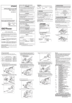
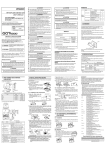
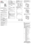
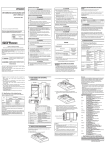
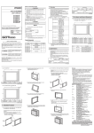
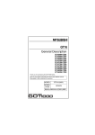
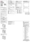
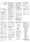
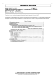
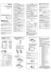
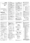
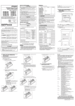
[BACKLIGHT REPLACEMENT PRECAUTIONS] DANGER GT16 Backlight for 12.1"/10.4" GOT User's Manual GT16-80SLTT GT16-70SLTT GT16-70VLTT GT16-70VLTN Make sure to externally shut off all phases of GOT power supply (when GOT is connected via the bus type connection, make sure to shut off all phases of PLC CPU power supply as well) and remove the GOT from the control panel before backlight replacement. If all phases are not shut off, it may cause an electric shock. If backlight is replaced with the GOT on the control panel, the GOT may drop off, resulting in injuries. CAUTION Make sure to wear gloves during backlight replacement. Failure to do so may cause injuries. Make sure to start the backlight replacement 5 or more minutes after power off of the GOT. Failure to do so may cause burn injuries as the old backlight holds heat for a while. [STARTUP AND MAINTENANCE PRECAUTIONS] Thank you for purchasing the GOT1000 Series. MODEL GT16-80SLTT-U MODEL CODE 1D7M83 IB(NA)-0800428-E(1202)MEE Before handling the GOT, make sure to touch a grounded metal object to discharge the static electricity from the human body. Failure to do so may cause the GOT to fail or malfunction. [DISPOSAL PRECAUTIONS] lSAFETY PRECAUTIONSl Before using this product, please read this manual and the relevant manuals introduced in this manual carefully and pay full attention to safety to handle the product correctly. The precautions given in this manual are concerned with this product. In this manual, the safety precautions are ranked as "DANGER" and "CAUTION". Indicates that incorrect handling may cause hazardous conditions, resulting in death or severe injury. Indicates that incorrect handling may cause hazardous conditions, resulting in medium or slight personal injury or physical damage. Note that the CAUTION level may lead to a serious accident according to the circumstances. Always follow the precautions of both levels because they are important to personal safety. Please save this manual to make it accessible when required and always forward it to the end user. (When replacing GT16-70SLTT/VLTT) 1. OVERVIEW Bottom This User's Manual describes GT16 backlight for 12.1"/10.4" GOT (hereinafter referred to as the backlight). For applicable GOTs, refer to GT16 User's Manual. Product Model Description GOT Backlight GT1680SLTT For 12.1" TFT (SVGA) of high intensity and GT1685M-S wide angle view GT1670SLTT For 10.4" TFT (SVGA) of high intensity and GT1675M-S wide angle view GT1670VLTT For 10.4" TFT (VGA) of high intensity and wide GT1675M-V*1 angle view GT16GT1675-VN For 10.4" TFT (VGA) 70VLTN GT1672-VN *1 Function version C or earlier For function version D or later, use the GT16-70VLTTA. 4) Remove eight fixing screws on the GOT rear face with a screwdriver. A 3.2 Replacing Backlight (1) GT16-80SLTT?GT16-70SLTT?GT16-70VLTT 1) Remove the cable connector of the backlight from the connector of the GOT board. (Expanded figure of part A in 3.1 4)) Top Make sure to transport the GOT main unit and/or relevant unit(s) in the manner they will not be exposed to the impact exceeding the impact resistance described in the general specifications of the GT16 User's Manual, as they are precision devices. Failure to do so may cause the unit to fail. Check if the unit operates correctly after transportation. The following shows the performance specifications of the backlight. The general specifications of the backlight are the same as those of the GOT. For the general specifications of the GOT, refer to GT16 User's Manual. Specifications Item GT16GT16GT16GT1680SLTT 70SLTT 70VLTT 70VLTN Type Manuals Life The following shows manuals relevant to this product. Weight When replacing the GT16-70SLTT/70VLTT, remove the cables from the cable holder. (When replacing GT16-70SLTT/VLTT). Cold cathode tube backlight 50,000h or more (Operating ambient temperature: 25 0.015kg (0.033lb) 0.008kg (0.018lb) ) 0.012kg (0.026lb) ケーブルホルダ Cable holder Detailed Manual Manual name Manual number (Model code) GT16 User's Manual(Hardware) (Sold separately) SH-080928ENG (1D7MD3) Relevant Manuals For relevant manuals, refer to the PDF manuals stored in the CDROM for the drawing software used. © 2008 MITSUBISHI ELECTRIC CORPORATION 3. BACKLIGHT REPLACEMENT 3.1 Preparing for Replacement The GOT includes the backlight for the liquid crystal display panel. The backlight intensity decreases with time. Replace the backlight when the display section becomes dark due to the decreased intensity and the picture is unclear. The following shows the procedures for replacing the backlight. 2) Press the backlight fixing latch (black) toward the direction of the following arrow with the screwdriver or others, and pull out the backlight to the left. Pull out the backlight so that the backlight does not hit the packing. (When replacing GT16-80SLTT) 1) Turn off the GOT. 2) Disconnect the power supply cable and the communication cable. Remove the GOT from the control panel. Remove the cables from the cable holder. Latch Warranty Mitsubishi will not be held liable for damage caused by factors found not to be the cause of Mitsubishi; machine damage or lost profits caused by faults in the Mitsubishi products; damage, secondary damage, accident compensation caused by special factors unpredictable by Mitsubishi; damages to products other than Mitsubishi products; and to other duties. Cable Cable holder Fluorescent tube Packing The latch is on the right side of the backlight. (Edge-on view figure of the part A in 3.1 4)) 2) Press the backlight fixing latch (black) toward the direction of the following arrow with the screwdriver or others, and pull out the backlight to the left. Pull out the backlight so that the backlight does not hit the packing. Latch Latch Press the latch toward the direction of the following arrows with the screwdriver or others. Fluorescent tube Packing Packing Fluorescent tube 3) Install a new backlight in the reverse procedure of removal. When inserting a new backlight into the backlight replacement hole of the GOT, make sure not to damage the sheaths of the cables. Insert the backlight until it is fixed by the latch (black). Assemble the case in the reverse procedure of disassembly. (Tighten the fixing screws on the GOT rear face with a torque of 0.36 to 0.48 N•m). When installing the case, make sure that the cables are not stuck between the case and the GOT. (2) GT16-70VLTN 1) Remove the cable connector of the backlight from the connector of the GOT board. (Expanded figure of part A in 3.1 4)) Top Top 2. SPECIFICATIONS CAUTION (Always read these precautions before using this equipment.) 3) Remove the right extension unit cover of the GOT. Remove an extension unit, including a bus connection unit, if it is mounted. CAUTION Dispose of this product as industrial waste. [TRANSPORTATION PRECAUTIONS] CAUTION After unpacking the box, check that the following products are included. Model Product Quantity GT16-80SLTT GT16-70SLTT Backlight 1 GT16-70VLTT GT16-70VLTN CAUTION Prior to use, please read both this manual and detailed manual thoroughly to fully understand the product. DANGER Packing List 3) Install a new backlight in the reverse procedure of removal. When inserting a new backlight into the backlight replacement hole of the GOT, make sure not to damage the sheaths of the cables. Insert the backlight until it is fixed by the latch (black). Assemble the case in the reverse procedure of disassembly. (Tighten the fixing screws on the GOT rear face with a torque of 0.36 to 0.48 N•m). When installing the case, make sure that the cables are not stuck between the case and the GOT For safe use • This product has been manufactured as a general-purpose part for general industries, and has not been designed or manufactured to be incorporated in a device or system used in purposes related to human life. • Before using the product for special purposes such as nuclear power, electric power, aerospace, medicine or passenger movement vehicles, consult with Mitsubishi. • This product has been manufactured under strict quality control. However, when installing the product where major accidents or losses could occur if the product fails, install appropriate backup or failsafe functions in the system. Country/Region Sales office/Tel U.S.A Mitsubishi Electric Automation Inc. 500 Corporate Woods Parkway Vernon Hills, IL 60061, U.S.A. Tel : +1-847-478-2100 Brazil MELCO-TEC Rep. Com.e Assessoria Tecnica Ltda. Rua Correia Dias, 184, Edificio Paraiso Trade Center-8 andar Paraiso, Sao Paulo, SP Brazil Tel : +55-11-5908-8331 Germany Mitsubishi Electric Europe B.V. German Branch Gothaer Strasse 8 D-40880 Ratingen, GERMANY Tel : +49-2102-486-0 U.K Mitsubishi Electric Europe B.V. UK Branch Travellers Lane, Hatfield, Hertfordshire., AL10 8XB, U.K. Tel : +44-1707-276100 Italy Mitsubishi Electric Europe B.V. Italian Branch Centro Dir. Colleoni, Pal. Perseo-Ingr.2 Via Paracelso 12, I-20041 Agrate Brianza., Milano, Italy Tel : +39-039-60531 Spain Mitsubishi Electric Europe B.V. Spanish Branch Carretera de Rubi 76-80, E-08190 Sant Cugat del Valles, Barcelona, Spain Tel : +34-93-565-3131 France Mitsubishi Electric Europe B.V. French Branch 25, Boulevard des Bouvets, F-92741 Nanterre Cedex, France Tel : +33-1-5568-5568 South Africa Circuit Breaker Industries Ltd. Private Bag 2016, ZA-1600 Isando, South Africa Tel : +27-11-928-2000 Hong Kong Mitsubishi Electric Automation (Hong Kong) Ltd. 10th Floor, Manulife Tower, 169 Electric Road, North Point, Hong Kong Tel : +852-2887-8870 China Mitsubishi Electric Automation (China) Ltd. 4/F Zhi Fu Plazz, No.80 Xin Chang Road, Shanghai 200003, China Tel : +86-21-6120-0808 Taiwan Setsuyo Enterprise Co., Ltd. 6F No.105 Wu-Kung 3rd.Rd, Wu-Ku Hsiang, Taipei Hsine, Taiwan Tel : +886-2-2299-2499 Korea Mitsubishi Electric Automation Korea Co., Ltd. 1480-6, Gayang-dong, Gangseo-ku Seoul 157-200, Korea Tel : +82-2-3660-9552 Singapore Mitsubishi Electric Asia Pte, Ltd. 307 Alexandra Road #05-01/02, Mitsubishi Electric Building, Singapore 159943 Tel : +65-6470-2460 Thailand Mitsubishi Electric Automation (Thailand) Co., Ltd. Bang-Chan Industrial Estate No.111 Moo 4, Serithai Rd, T.Kannayao, A.Kannayao, Bangkok 10230 Thailand Tel : +66-2-517-1326 Indonesia P.T. Autoteknindo Sumber Makmur Muara Karang Selatan, Block A/Utara No.1 Kav. No.11 Kawasan Industri Pergudangan Jakarta - Utara 14440, P.O.Box 5045 Jakarta, 11050 Indonesia Tel : +62-21-6630833 India Messung Systems Pvt, Ltd. Electronic Sadan NO:III Unit No15, M.I.D.C Bhosari, Pune-411026, India Tel : +91-20-2712-3130 Australia Mitsubishi Electric Australia Pty. Ltd. 348 Victoria Road, Rydalmere, N.S.W 2116, Australia Tel : +61-2-9684-7777 HEAD OFFICE : TOKYO BUILDING, 2-7-3 MARUNOUCHI, CHIYODA-KU, TOKYO 100-8310, JAPAN NAGOYA WORKS : 1-14, YADA-MINAMI 5-CHOME, HIGASHI-KU, NAGOYA, JAPAN When exported from Japan, this manual does not require application to the Ministry of Economy, Trade and Industry for service transaction permission. Specifications subject to change without notice. Printed in Japan, February 2012.