Transcript
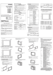
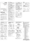
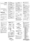
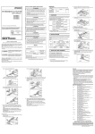
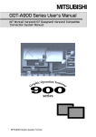
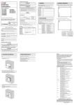
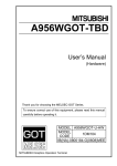
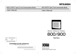
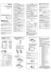
[INSTALLATION PRECAUTIONS]
1. Overview
GT15 ATTACHMENT
User's Manual
GT15-70ATT-98
GT15-70ATT-87
GT15-60ATT-97
GT15-60ATT-96
GT15-60ATT-87
GT15-60ATT-77
GT15-50ATT-95W
GT15-50ATT-85
z When mounting the attachment to the control panel, tighten
clamp screws in the specified torque range so that it will be
securely fixed.
Failure to do so may cause the attachment to drop from the
control panel.
z When mounting the GOT to the attachment, tighten clamp
screws in the range of 0.36 to 0.48N•m so that it will be securely
fixed.
Loose tightening may cause the GOT to drop from the
attachment.
Overtightening may damage and drop screws and/or GOT,
causing the GOT to drop off, fail or malfunction.
CAUTION
z Dispose of this product as industrial waste.
Manuals
The following shows manuals relevant to this product.
Prior to use, please read both this manual and detailed
manual thoroughly to fully understand the product.
MODEL
GT15-ATT-U
MODEL
CODE
1D7M02
Detailed Manual
Manual number
(Type code)
Manual name
GT16 User's Manual
IB(NA)-0800296-E(0901)MEE
(Sold separately)
SH-080778ENG
(1D7M88)
(Sold separately)
SH-080528ENG
(1D7M23)
GT15 User's Manual
Relevant Manuals
For relevant manuals, refer to the PDF manuals stored in the GT
Designer2 CD-ROM.
© 2004 MITSUBISHI ELECTRIC CORPORATION
lSAFETY PRECAUTIONSl
(Always read these precautions before using this equipment.)
Before using this product, please read this manual and the relevant
manuals introduced in this manual carefully and pay full attention to
safety to handle the product correctly.
The precautions given in this manual are concerned with this product.
In this manual, the safety precautions are ranked as "DANGER" and
"CAUTION".
DANGER
CAUTION
Product Components
The attachment consists of the following items.
Model
GT15-70ATT-98
Product
Attachment
Quantity
1
Clamp screw (M4x8mm)
4
GT15-70ATT-87
Attachment
1
Indicates that incorrect handling may cause
hazardous conditions, resulting in death or
severe injury.
GT15-60ATT-97
GT15-60ATT-96
GT15-60ATT-87
GT15-60ATT-77
Attachment
1
Clamp screw (M4x8mm)
4
Indicates that incorrect handling may cause
hazardous conditions, resulting in medium or
slight personal injury or physical damage.
GT15-50ATT-95W
GT15-50ATT-85
Attachment
1
Note that the
CAUTION level may lead to a serious accident
according to the circumstances.
Always follow the precautions of both levels because they are important to personal safety.
Please save this manual to make it accessible when required and
always forward it to the end user.
(2) GT15-70ATT-87
C
A
Product
Model
A985GOT*1
10.4" GOT1000
A870GOT-SWS,
A870GOT-TWS,
A8GT-70GOT-TW,
GT15-70ATT-87
A8GT-70GOT-TB,
A8GT-70GOT-SW,
A8GT-70GOT-SB
10.4" GOT1000
A97 GOT
GT15-60ATT-97
8.4" GOT1000
A960GOT
GT15-60ATT-96
8.4" GOT1000
A870GOT-EWS,
A8GT-70GOT-EW,
Attachment
A8GT-70GOT-EB,
GT15-70ATT-87
A77GOT-EL-S5,
A77GOT-EL-S3,
A77GOT-EL
8.4" GOT1000
A77GOT-CL-S5,
A77GOT-CL-S3,C
A77GOT-CL,
GT15-60ATT-77
A77GOT-L-S5,
A77GOT-L-S3,
8.4" GOT1000
A956WGOT
GT15-50ATT-95W
5.7" GOT1000
A85 GOT
GT15-50ATT-85
5.7" GOT1000
*1 The GP250 and GP260 manufactured by Digital
Electronics Corporation can also be replaced with the 10.4"
GOT1000.
2. Specifications
The following table indicates the performance specifications of
the attachment.
The general specifications of the attachment are the same as
those of the GOT.
For the general specifications of the GOT, refer to GT16 User's
Manual or GT15 User's Manual.
After replacement using the attachment, the replaced GOT
does not comply with IP65 (waterproof, dustproof standards),
although compliant with IP4X.
Item
GT1570ATT-98
Specifications
GT15GT1560ATT-97 60ATT-96
2) Hang the two upper hooks on the upper part over the
mounting holes in the control panel.
Refer to the figure shown in 1).
(2) GT15-70ATT-87, GT15-50ATT-95W, GT15-50ATT-85
The following figures show an example of the GT15-70ATT-87
installation.
Follow the same procedure for installing the other models.
B
3) While lifting the attachment upward, hang the two lower
hooks on the lower part of the control panel.
B
222 (8.7)
C
5.5 (0.2)
Unit: mm (inch)
Upper
part
Upper
part
(3) GT15-50ATT-95W, GT15-50ATT-85
C
Lower
part
Lower
part
4) Fix the attachment to the control panel with four clamp
screws in the torque range of 0.2 to 0.28N•m.
2) Remove two-sided tapes from the rear face of the
attachment.
5) Place the GOT into the attachment from the front, and fix it
by tightening the mounting screws included with the GOT in
the torque range of 0.36 to 0.48N•m.
3) Fix the attachment to fit the mouting hole on the control
panel.
If the control panel is dirty, the attachment might fall,
causing an injury.
Wipe the control panel, and then install the attachment.
B
A
Model
GT15-50ATT-95W
GT15-50ATT-85
A
216 (8.1)
194 (7.6)
B
137 (5.4)
137 (5.4)
C
2.6 (0.1)
2.6 (0.1)
Unit: mm (inch)
4. Installation Procedure
(1) GT15-70ATT-98, GT15-60ATT-97, GT15-60ATT-96,
GT15-60ATT-87, GT15-60ATT-77
The following figures show an example of the GT15-60ATT-97
installation.
Follow the same procedure for installing the other models.
1) The model is indicated on the attachment.
The upper part of the attachment has the model indication.
(Example of model indication)
Model
Upper
part
Upper
part
Weight
GT1560ATT-77
2 to 3 mm (0.08 to 0.12 inch)
0.25(0.55)
0.11(0.24)
0.17(0.37)
0.34(0.75)
Unit: kg (lb)
3. Part Names and External Dimensions
(1) GT15-70ATT-98, GT15-60ATT-97, GT15-60ATT-96,
GT15-60ATT-87, GT15-60ATT-77
C
A
1)
3)
2)
Model name
GT15-70ATT-98
GT15-60ATT-97
GT15-60ATT-96
GT15-60ATT-87
GT15-60ATT-77
A
314 (12.4)
300 (11.8)
270 (10.6)
278 (10.9)
313 (12.3)
B
240 (9.4)
212 (8.3)
195 (7.7)
195 (7.7)
195 (7.7)
C
8.5 (0.3)
8.5 (0.3)
8.5 (0.3)
8.5 (0.3)
8.5 (0.3)
Unit: mm (inch)
No.
Name
1
Upper hook
2
Lower hook
3
Clamp screw
Description
Hook for hanging the attachment
on the control panel upper part.
Hook for hanging the attachment
on the control panel lower part.
Screw for fixing the attachment to
the control panel (M4x8mm)
Mounting panel
2 to 3 mm (0.08 to 0.12 inch)
thickness
Weight
0.29(0.64) 0.40(0.88) 0.24(0.53) 0.12(0.26)
Unit: kg (lb)
Model
A
311 (12.2)
Mounting panel
thickness
Specifications
GT1550ATT95W
GT1550ATT-85
GT1570ATT-87
1) The model is indicated on the attachment.
The position of the model indication does not affect the
performance of the attachment.
(Example of model indication)
Model
GT15-70ATT-87
GT1560ATT-87
Description
GT15-70ATT-98
[DISPOSAL PRECAUTIONS]
Thank you for purchasing the GOT1000 Series.
This User's Manual describes the GT15 panel fixing attachment
(hereafter abbreviated to the attachment).
The attachment is used for replacing the A985GOT,
A97 GOT, A960GOT, A956WGOT, A870GOT, A85 GOT,
and A77GOT with the GOT1000 series.
Use of the attachment eliminates the need for the additional
machining of the control panel or similar enclosure used with
the A97 GOT or A960GOT.
There are the following attachment types.
Refer to GT16 User's Manual or GT15 User's Manual for the
applicable GOT.
Item
B
CAUTION
4) Place the GOT into the attachment from the front, and fix it
by tightening the mounting screws included with the GOT in
the torque range of 0.36 to 0.48N•m.
Warranty
Mitsubishi will not be held liable for damage caused by factors found
not to be the cause of Mitsubishi; machine damage or lost profits
caused by faults in the Mitsubishi products; damage, secondary
damage, accident compensation caused by special factors
unpredictable by Mitsubishi; damages to products other than
Mitsubishi products; and to other duties.
For safe use
• This product has been manufactured as a general-purpose part for
general industries, and has not been designed or manufactured to
be incorporated in a device or system used in purposes related to
human life.
• Before using the product for special purposes such as nuclear
power, electric power, aerospace, medicine or passenger
movement vehicles, consult with Mitsubishi.
• This product has been manufactured under strict quality control.
However, when installing the product where major accidents or
losses could occur if the product fails, install appropriate backup or
failsafe functions in the system.
Country/Region Sales office/Tel
U.S.A
Mitsubishi Electric Automation Inc.
500 Corporate Woods Parkway Vernon Hills, IL 60061, U.S.A.
Tel : +1-847-478-2100
Brazil
MELCO-TEC Rep. Com.e Assessoria Tecnica Ltda.
Rua Correia Dias, 184, Edificio Paraiso Trade Center-8 andar
Paraiso, Sao Paulo, SP Brazil
Tel : +55-11-5908-8331
Germany
Mitsubishi Electric Europe B.V. German Branch
Gothaer Strasse 8 D-40880 Ratingen, GERMANY
Tel : +49-2102-486-0
U.K
Mitsubishi Electric Europe B.V. UK Branch
Travellers Lane, Hatfield, Hertfordshire., AL10 8XB, U.K.
Tel : +44-1707-276100
Italy
Mitsubishi Electric Europe B.V. Italian Branch
Centro Dir. Colleoni, Pal. Perseo-Ingr.2
Via Paracelso 12, I-20041 Agrate Brianza., Milano, Italy
Tel : +39-039-60531
Spain
Mitsubishi Electric Europe B.V. Spanish Branch
Carretera de Rubi 76-80,
E-08190 Sant Cugat del Valles, Barcelona, Spain
Tel : +34-93-565-3131
France
Mitsubishi Electric Europe B.V. French Branch
25, Boulevard des Bouvets, F-92741 Nanterre Cedex, France
TEL: +33-1-5568-5568
South Africa
Circuit Breaker Industries Ltd.
Private Bag 2016, ZA-1600 Isando, South Africa
Tel : +27-11-928-2000
Hong Kong
Mitsubishi Electric Automation (Hong Kong) Ltd.
10th Floor, Manulife Tower, 169 Electric
Road, North Point, Hong Kong
Tel : +852-2887-8870
China
Mitsubishi Electric Automation (Shanghai) Ltd.
4/F Zhi Fu Plazz, No.80 Xin Chang Road,
Shanghai 200003, China
Tel : +86-21-6120-0808
Taiwan
Setsuyo Enterprise Co., Ltd.
6F No.105 Wu-Kung 3rd.Rd, Wu-Ku Hsiang,
Taipei Hsine, Taiwan
Tel : +886-2-2299-2499
Korea
Mitsubishi Electric Automation Korea Co., Ltd.
1480-6, Gayang-dong, Gangseo-ku Seoul
157-200, Korea
Tel : +82-2-3660-9552
Singapore
Mitsubishi Electric Asia Pte, Ltd.
307 Alexandra Road #05-01/02,
Mitsubishi Electric Building, Singapore 159943
Tel : +65-6470-2460
Thailand
Mitsubishi Electric Automation (Thailand) Co., Ltd.
Bang-Chan Industrial Estate No.111 Moo 4, Serithai Rd,
T.Kannayao, A.Kannayao, Bangkok 10230 Thailand
Tel : +66-2-517-1326
Indonesia
P.T. Autoteknindo Sumber Makmur
Muara Karang Selatan, Block A/Utara
No.1 Kav. No.11 Kawasan Industri Pergudangan
Jakarta - Utara 14440, P.O.Box 5045 Jakarta, 11050 Indonesia
Tel : +62-21-6630833
India
Messung Systems Pvt, Ltd.
Electronic Sadan NO:III Unit No15, M.I.D.C Bhosari,
Pune-411026, India
Tel : +91-20-2712-3130
Australia
Mitsubishi Electric Australia Pty. Ltd.
348 Victoria Road, Rydalmere, N.S.W 2116, Australia
Tel : +61-2-9684-7777
HEAD OFFICE : TOKYO BUILDING, 2-7-3 MARUNOUCHI, CHIYODA-KU, TOKYO 100-8310, JAPAN
NAGOYA WORKS : 1-14, YADA-MINAMI 5-CHOME, HIGASHI-KU, NAGOYA, JAPAN
When exported from Japan, this manual does not require application to the Ministry
of Economy, Trade and Industry for service transaction permission.
Lower
part
Lower
part
Specifications subject to change without notice.
Printed in Japan.