1
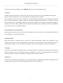
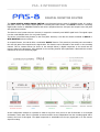
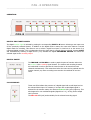
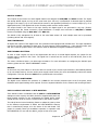
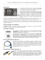
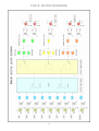
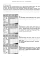
MANUAL
DIGITAL AUDIO-ROUTER
CONTENTS
__________________________________________________________________________________
PLEASE NOTE
page
3
INTRODUCTION
page
4..5
OPERATION
page
6
AUDIO FORMAT AND CONFIGURATION
page
7
INPUT CONFIGURATION
page
8
AUDIO SIGNAL QUALITY
page
9
POWER SUPPLY
page
10
OPTIONAL VERSIONS AND ACCESSORIES
page
10
CABLING AND SIGNAL DISTRIBUTION
page
11..12
PIN ASSIGNMENT
page
9..10
BLOCK CIRCUIT DIAGRAM
page
13
MEASUREMENT GRAPHS FOR JITTER SPECTRUM
page
14
TECHNICAL SPECIFICATIONS
page
15
ELECTROMAGNETIC INTERFERENCE
page
16
MAINTENANCE AND REPAIR
page
17
CE DECLARATION OF CONFORMITY
page
18
2
PLEASE NOTE
____________________________________________________________________________________________________
This user manual only applies to the PAS-8 digital router with 8 digital inputs.
CAUTION:
Always connect this device to a 230 VAC /50..60 Hz (115 VAC /50—60 Hz) earthed power supply.
Never connect the device to any outlet without a protective earth contact!
Never expose the device to rain or moisture, as this creates a hazard of fire and electrical shock. Do
not connect the device to a power supply if it has been damaged mechanically, or if fluids or objects
have entered into it. Immediately disconnect the power supply in the event of mechanical damage or
contact with fluids. Only qualified service personnel following all applicable rules and regulations
may open the device or perform repairs.
ENVIRONMENTAL REQUIREMENTS:
Never place the device near heat sources like radiators or hot-air vents. Do not expose the device to
dust, vibration, or mechanical shocks.
CONDENSATION:
When the device is brought from a cold into a warm environment, water may condense in the
interior, and there is a risk of malfunction. Do not turn on the device for thirty minutes after such a
temperature change in order to allow the PAS-8 to assume the temperature of the environment.
CLEANING:
Use a soft cloth slightly moistened with a mild soap solution for cleaning the casing, the front panel,
and the controls. Do not use abrasive pads or powders or alcohol or petroleum-based solvents to
clean the device, as this may damage the casing surface and the controls.
WARRANTY:
This device has a three-year warranty. Any manufacturing or material defects will be repaired free of
charge during this period. Unauthorised opening will void the warranty!
3
PAS - 8 INTRODUCTION
___________________________________________________________________________________________________
DIGITAL MONITOR ROUTER
The PAS-8 DIGITAL AUDIO SIGNAL SWITCH is a professional monitor router for AES/EBU signals. It is used to
play back, record, and monitor digital signals in recording and video studios. The PAS-8 is ideal for connecting
digital audio devices to AES/EBU interfaces and various peripheral devices. All inputs and outputs have XLR jacks
with gold-plated contacts.
The PAS-8 is not a format converter. However, it accepts the commonly used SPDIF signal levels. The signal output
is at the usual AES/EBU level of 4 Vss (peak to peak).
The device is controlled using buttons on the front panel. However, it can also be remote controlled via AMS-2 or
MTX-MONITOR monitor systems.
As a special feature, the PAS-8 offers a switchable INSERT function. This permits a processing unit connected to
the rear XLR jacks to be looped into the signal chain. This function can be selected for the monitor or the recording
channel. This for instance allows (as shown in the example below) a digital compressor to be routed into the
monitor channel for adjustment, then switched to the recording channel after optimisation. Afterwards the monitor
channel will be free for monitoring again.
At this configuration example it is possible to make a copy from every source to the CD-Recorder or to the digtal
workstation. At the same time it is possible to monitor another source independent from the recording signal and to
measure the level of this signal. The digital compressor is switchable into the copy signal path or to the monitor
signal for testing.
4
PAS - 8 INTRODUCTION
_____________________________________________________________________________________________
CIRCUITRY:
The router's active circuitry ensures low jitter, which makes the device suitable for use before a D/A converter in
the signal chain. In order to improve the operation of a subsequent converter, the output amplifiers of the PAS-8
come with DUTY CYCLE correction. This ensures a DC-free output signal irrespective of the signal level and duty
cycle (mean time ratio of positive and negative bits) of the selected source, in addition to reducing potential jitter
caused by the low-pass effect of a connected line.
SYNCHRONISATION:
The PAS-8 does not require external synchronisation. If the router is operated as a signal switch in a synchronised
periphery environment, then signal switch-over is noise-free for two identically modulated signal sources, as well as
for digital = 0. The same is true for switchover between two signals derived from a single source by splitting
between two matrix inputs.
Switching between two differently modulated signals however produces a cracking noise due to the level difference
at the moment of switchover. This type of switchover noise is inherent to the design of fast switching analogue and
digital matrices.
The delay between switching off the first signal and switching on the new signal is in the nanosecond range
(10-8...10-9 s).
FRONT PANEL
MONITOR SELECT:
Two symmetrical stereo routers (monitor and recording router) form the core of the PAS-8. The MONITOR
ROUTER is used to select the desired monitor signal.
RECORD SELECT:
Selecting the RECORD ROUTER allows a signal to be selected as the recording source independent of the signal
source.
DIGITAL INSERT:
This button is used to insert an external digital processing unit into the monitor or recording channel.
FUSE 50 mAt
RECORD B
RECORD A
MONITOR B
MONITOR A
INSERT RET.
BACK PANEL
5
INPUT 8
INPUT 7
INPUT 6
INPUT 5
INPUT 4
INPUT 3
INPUT 2
INPUT 1
PAS - 8 OPERATION
_____________________________________________________________________________________________________
OPERATION:
DIGITAL INPUT SWITCHOVER:
The digital monitor signal is selected by pushing the corresponding INPUT 1..8 button. Selecting a new input turns
off the previously selected channel. In addition to the digital monitor matrix, the router also features a second
digital matrix for recording. This allows a user to select a signal from inputs 1..8 and use it as the source for a
connected digital recorder. This is independent from the signal that is currently being monitored. Pressing SHIFT
and simultaneously selecting a digital source (1..8) activates the digital RECORDING MATRIX and routes the
selected signal to the recording output.
DIGITAL INSERT:
The INS.MON and INS.REC are used to patch the point of insertion either into
the monitor or the recording signal channel. The monitor and recording channels
are interlocked in order to prevent the insert function to be routed into both
channels simultaneously. This means that before the insert can be patched into the
monitor channel, any active recording insert needs to be switched off and vice
versa.
CLOCK DISPLAY:
These two LEDs indicate the presence of a digital signal with a valid input level at
the selected PAS-8 input. For instance, if an input with a valid digital signal is
selected for the monitor matrix, the relevant MON.CLK LED (green) lights up. This
also happens for non-modulated signals (digital level = 0), as long as the sample
rate is present.
The REC.CLK LED (red) works similarly for the selected recording signal.
6
PAS - 8 AUDIO FORMAT and CONFIGURATIONS
___________________________________________________________________________________________________
DIGITAL FORMAT:
The 8 inputs of the router's two active digital matrices are designed for AES/EBU and AES-3 formats. The inputs
also accept SPDIF signals, as long as the usual level (400...500 mV) is maintained. A selected signal is patched
through to the output (e.g. for an external D/A converter) and provided (buffered) to a second output (e.g. for a
digital peak meter). This applies both to the recording matrix and the monitor matrix.
The output format is the same as the input format; the digital signal is not processed in any way. (Further
processing steps like format conversion, signal distribution or sample rate conversion in AES/EBU or SPDIF
format are available using the DAS-SRC or the DDA-12).
The PAS-8 is fully transparent for all data in the serial data stream. All usual sample rates can be processed
(including 96 kHz and 24 bit signals).
INPUT IMPEDANCE:
All inputs and outputs of the digital router are symmetrical and equipped with transformers. The input impedance
can also be set later, separately for each input, by using jumpers. Input impedance is >1 kW with the jumper open
and 110 W with the jumper closed. This makes it easier to distribute the signal to additional recipients.
INPUT SIGNAL SPLITTING:
In order to send a signal not only to the digital switch but also to a second digital recipient, the jumper for the
relevant input is opened in the router. The signal line is routed from the source to the PAS-8 first, then to the
second recipient.
The router is delivered with a 110 Ohm input terminator. For more information on configuring the PAS-8's input
resistors, please see the "INPUT IMPEDANCE" section.
BACKUP:
In the event of a power failure or when the device is turned off, the current input selection is automatically backed
up in non-volatile memory. As soon as the power supply is back online, the router automatically restores the stored
configuration. This also allows the PAS-8 to be operated with a time switch.
INPUT SIGNAL MONITORING:
The digital router indicates the presence of a clock for the currently selected input at the front panel, which
facilitates quick signal tracking when required. There are separate indicators for the monitor and recording channel.
PAS-8 combined with AMS-2 or MTX-MONITOR:
If the PAS-8 is used in combination with an AMS-2 or MTX-MONITOR
analogue monitor system, the PAS-8 should be supplied with power via
these monitor systems. In this configuration the PAS-8 power switch
should left off in order to ensure a central reset by the monitor system.
The PAS-8 has an internal switching feature to adapt the start-up time
to the different requirements of AMS-2 and MTX-MONITOR. Start-up
time is controlled by Jumper 16 in the centre of the main board. This
jumper is normally closed (for standalone operation or operation with
MTX-MONITOR). For use with the AMS-2, jumper 16 has to be open.
Jumper 16
7
PAS-8 INPUT CONFIGURATION
___________________________________________________________________________________________________
CHANGING THE INPUT IMPEDANCE:
The jumpers for input impedance selection can be reached by opening the device cover. If the jumper is on both
contacts, input impedance is 110 Ω. If the jumper is on only one contact, the input impedance is >1 kΩ. The PAS-8
has 8 jumpers for its 8 inputs and an additional jumper for the digital insert input.
Jumper for Input impedance 1..8
Jumper for insert
SPDIF SIGNALS TO BALANCED AES/EBU INPUTS:
If an SPDIF signal is fed in through the XLR inputs, the impedance at the connected XLR
plug should be adjusted by wiring a 232 W resistor in parallel between pins 2 and 3. This
sets the input to a characteristic impedance of 75 Ω, which is common for SPDIF signals.
The "hot" wire of the incoming line is connected to pin 2, while the shielding is connected
to pins 3 and 1 of the XLR plug.
Pin 1 on the XLR plug is left open if the sending device and the PAS-8 need to be
galvanically separated. The shielding is only connected to pin 3 in this case.
The figure shows the solder side of the XLR plug.
Pre-assembled adapter cables for this purpose are available under the name CASA.
The CASA-T cable has similar functions, but works using an integrated fast pulse
transformer, which allows it to be used with non-standard balanced inputs (without an
input transformer).
8
AUDIO SIGNAL QUALITY
___________________________________________________________________________________________________
INPUT AND OUTPUT AMPLIFIERS
The PAS-8 is designed not only as a recording signal switch, but primarily as a high-quality monitor matrix for use
with an external D/A converter. In order to guarantee the required high signal quality, all the outputs of these
routers are equipped with automatic duty cycle post-correction (positive and negative pulse widths are balanced).
This keeps the bit width (duty cycle) more or less constant even for highly different input levels and varying rise
and fall times of the signal at the input. The same applies to the PAS-8's insert channel.
The above diagram illustrates the operating principle of the duty cycle correction. The upper, red curve shows a
highly misaligned input signal with an additional offset in the duty cycle of 30/70 (uppermost line of the readings).
The signal level is approx. 3.5 Vss. The lower, blue curve shows the PAS-8's corrected, clean output signal with a
symmetrical duty cycle of typically 50 % (lines 2 to 5 of the readings). The diagram also shows the accurately
defined, overshoot-free rise and fall times as well as the delay between input and output.
All amplifier stages are optimised for minimum jitter. The latency between input and output is approx. 60 ns
(nanoseconds) for the monitor channel and 70 ns for the recording channel. An active insert in the PAS-8 adds 30
ns. These extremely short latencies allow the device to be used even in highly complex, synchronous studio
systems.
9
PAS-8 POWER SUPPLY OPTIONAL VERSIONS
_______________________________________________________________________________
POWER SUPPLY
Protective earth and technical earth are separate in the PAS-8.
This isolates the audio circuits from parasitic currents in the
19-inch rack or the protective earth conductor.
Technical earth and chassis are connected internally via several
parallel 0.047 µF capacitors. This creates a low-resistance
connection that serves as a HF shield, while simultaneously
preventing the formation of a ground loop for the mains
frequency and its harmonics. Thanks to these features, the
matrix is suitable for use with various earthing strategies in the
studio.
The router works flawlessly even when exposed to mains voltage fluctuations between 180 and 245 VAC. The PAS8's stabilised supply voltages are short-proof and can be monitored by means of an LED in the front panel.
The mains fuse is in the power cable socket below the cable gland. The duct can be pulled out using a small
screwdriver. The duct also contains a spare fuse. If a new fuse is required, only uses fuses of the type 5 x 20 mm,
50 mA/250 V, anti-surge.
OPTIONAL VERSIONS and ACCESSORIES
The PAS-8 is available in two versions for different supply voltages: 230 V/50 Hz, or 115 V/50..60 Hz. Only the
manufacturer may convert the device for a different power supply.
ACCESSORIES – INTERFACE
In the pack panel of the digital audio router there is a 4-pole mini DIN socket labelled
PAS REMOTE. It is used for connecting a serial remote controller. The remote
controller has feedback LEDs for all functions.
This remote jack also allows for the PAS-8 inputs to be switched via the AMS-2 audio
monitor system or the MTX monitor. In this case the PAS-8 is supplied with power
via the MTX monitor or the AMS-2 and can be controlled simultaneously both at the
PAS-8 itself and from the analogue monitor systems. The PAS-8's power supply should
be turned off (power switch) in order to ensure a centralised reset at start-up.
AES/EBU Þ SPDIF ADAPTER CABLE (UAS)
This cable is used to adapt the level, impedance and balance of digital XLR outputs,
allowing the PAS-8 outputs to be connected to unbalanced coaxial inputs. Levels,
balancing and impedance are converted to standard SPDIF values without any format
conversion taking place. Please note that the receiving device needs to be able to
process the transmitted format. The cable is usable for sample rates up to 192 kHz.
Available lengths: 0.5 m, 1.0 m, 2.0 m and 3.5 m.
SPDIF Þ AES/EBU ADAPTER CABLE (CASA-T)
This cable is used to adapt the impedance and unbalance of digital SPDIF outputs to
balanced 110 Ω AES/EBU Inputs, allowing the PAS-8 inputs to be connected to
unbalanced coaxial inputs. Balancing and impedance are converted to standard
AES/EBU values without any format conversion taking place. Please note that the
receiving device needs to be able to process the transmitted format. The cable is
usable for sample rates up to 192 kHz. Available lengths: 0.5, 1.0, 2.0 and 3.5 m.
10
PAS - 8 WIRING
___________________________________________________________________________________________________
CONNECTIONS
BALANCED INPUTS:
All balanced inputs are equipped with NEUTRIK XLR FEMALE jacks with gold-plated
contacts. The pin assignment is according to professional industry standards (see figure).
Protective earth and technical earth are separate in the PAS-8. To prevent ground loops
via the input cables (XLR pin 1), pin 1 is not wired to technical earth internally, but to the
chassis via an intermediate capacitor. This is to prevent interference currents via pin 1
from creating a voltage drop over the ground wire's internal resistance, which could
potentially interfere with the signal. This capacitor acts as an isolator for the mains
voltage for all practical purposes, while also functioning as a low-resistance dissipater for
high frequencies.
BALANCED OUTPUTS:
All balanced outputs are equipped with NEUTRIK XLR MALE jacks with gold-plated
contacts. The pin assignment is according to professional industry standards (see figure).
Protective earth and technical earth are separate in the PAS-8. To prevent ground loops
via the outputs (pin 1), pin 1 is not wired to technical earth internally but to the chassis
via an intermediate capacitor. This is to prevent interference currents via pin 1 from
creating a voltage drop over the ground wire's internal resistance, which could potentially
interfere with the signal. This capacitor acts as an isolator for the mains voltage for all
practical purposes, while also functioning as a low-resistance dissipater for high
frequencies.
SPDIF SIGNALS TO BALANCED INPUTS:
If an SPDIF signal is fed in through the XLR inputs, the impedance at the connected XLR
plug should be adjusted from 110 W to 75 W by wiring a 232 W resistor in parallel
between pins 2 and 3. The "hot" wire of the incoming line is connected to pin 2, the
shielding is connected to pins 3 and 1 of the XLR plug.
If there is a risk of a ground loop forming between the sending device and PAS-8, then
pin 1 should not be connected. The shield of the unbalanced signal source will be
terminated on pin 3 of the XLR input in this case.
We offer pre-made adapter cables of various lengths as accessories, including impedance
adaptation from RCA to XLR for digital audio applications. In these cables, the
transmitter's and the recipient's earths are galvanically separated (UAS-cable and CASAT-cable). This prevents the formation of a ground loop through this connection. The
shielding is terminated on the RCA plug casing.
MAINS CONNECTOR IN THE BACK PANEL:
Always use a power cable with a protective earth conductor and a Schuko
plug (included) to connect this device to mains power. A chassis screw
next to the power jack can be used to create a low-ohm connection to
the rack. If the device is used with the AMS-2 audio monitor system, this
contact should be connected to the chassis jack of the AMS-2.
11
DIGITAL ROUTER PAS-8 CONNECTIONS
____________________________________________________________________________________________________
EXAMPLE CONNECTIONS FOR DIGITAL RECORDING CHANNELS
The drawing below shows an example connection for recording signals (recording matrix). Since AES/EBU signals
cannot simply be distributed to several recipients in parallel, the use of an AES/EBU distribution amplifier is
recommended for more than 4 digital recipients. As an example, the following figure illustrates the use of a DDA-12
distribution amplifier in conjunction with the PAS-8.
This configuration allows any recipient to record signals from any source. The switching options of the DDA-12
permit the signal to be routed to input 2 of the DDA-12 instead of the D/A converter or the digital peakmeter.
Either the monitor or the recording signal can be used as the source. Moreover, it is possible to send both the
monitor and recoding signals simultaneously to different recipients for recording.
PAS-8
DDA-12
12
PAS-8 BLOCK DIAGRAM
13
PAS-8 TECHNICAL APPENDIX
____________________________________________________________________________________________________________________________________________________________________
JITTER ANALYSES:
Small time offsets (jitter) of individual flanks are the main cause of quality degradation in digital audio signal
transmission. High-quality transmission therefore requires a reduction of the jitter to a minimum.
The router's active circuitry ensures low jitter, which makes the device highly suitable for use before a D/A
converter in the signal chain. The additional DUTY CYCLE correction ensures a DC-free output signal irrespective
of signal levels and duty cycle (mean time ratio of positive and negative bits) of the selected source, in addition
to reducing potential jitter caused by the low-pass effect of a connected cable. The figures below show jitter
measurements for the PAS-8 and the AMS-2 DAR and illustrate the extremely low jitter in the signal processing.
Fig. 1:
The measurement record on the left shows the jitter spectrum
of the testing device (Rhode & Schwarz UPL). All
measurement records are scaled identically. The evaluated
measurement range is from a few Hz up to 120 kHz.
Fig. 2:
Measurement at the PAS-8 monitor output. Despite the
measuring device's extremely high resolution, it shows that
there is hardly any increase of jitter across the entire
spectrum. All readings are very close to the sensitivity limit of
the measuring device. The highest recorded jitter is at approx.
1 nanosecond, and effective jitter is below 300 ps (10-12
seconds!). Signal input was at input 1.
Fig. 3:
Measurement at the PAS-8 monitor output, signal input at
insert return. Despite the measuring device's extremely high
resolution, it hardly shows any increase of jitter across the
whole spectrum compared with fig. 1. Again, rms jitter is
below 300 ps.
The highest recorded peak jitter is at approx. 1 nanosecond
(10-12 seconds!).
Fig. 4:
Measurement at the monitor output of the PAS-8. Audio signal
input was via input 1 at a sample rate of 96 kHz and a level of
approx. 4 Vss. All AES/EBU cables have lengths of approx.
2 m. Rms jitter is below 150 ps. The highest recorded peak
jitter is at approx. 420 ps.
14
TECHNICAL SPECIFICATIONS PAS-8
__________________________________________________________________________________________________________________
Number of inputs :......................................... 8 Inputs
Number of outputs : ...................................... 2 Monitor
1 Insert return
2 Record
1 Insert send
Connector inputs: .......................................... XLR female gold-plated contacts
Connector outputs: ........................................ XLR male gold-plated contacts
Digital format : .............................................. AES/EBU / AES-3 [also SPDIF with adapter plug] (transparent for all formats)
Sampling frequency :..................................... depends from input signal (25...105 kHz)
Input voltage range :..................................... 300 mV...5V pp
Input impedance: .......................................... 110 Ω (1 kΩ without internal jumpers) transformer balanced, free of ground
Common mode input voltage, max. : ............ ± 60V
Output voltagel:............................................. 4,0 V pp at 110 Ω
Output impedance: ........................................ 110 Ω transformer balanced, free of earth
Common mode output voltage, max. :.......... ± 60V
Rise time : ...................................................... 20 ns
Delay time input-output :.............................. 60...80 ns
Synchronisation :........................................... external synchronisation is not required
Remote control format : ................................ seriell balanced, likewise RS422
Power supply : ............................................... 230 V / 50...60 Hz (115 V / 60 Hz optional)
Power consumption :..................................... 3 VA
Fuse :.............................................................. 50 mAt/250V 5 x 20 mm
Protection class : ........................................... 1
Case: .............................................................. steel, light grey
Front panel: aluminium, light grey (RAL 7035)
Dimensions : .................................................. 483 mm x 250 mm x 44 mm (width x depht x height)
Warranty : ...................................................... 3 years
Do not connect signals with levels above 10 Vpp to the inputs, as they may damage the device.
15
ELECTROMAGNETIC INTERFERENCE
____________________________________________________________________________________________________
ELECTROMAGNETIC INTERFERENCE and EMC
This device complies with the EMC requirements as defined in the directives 89/336/EEC and FCC part 15:
The device's electromagnetic emissions are sufficiently low to not interfere with the intended use of other devices
and systems.
The device is sufficiently resistant to electromagnetic interference for its intended use.
The device has been tested and fulfils the requirements below:
Safety:
Protection acc. to EN60950; 1992 + A1/A2; 1993 (UL1950)
EMC:
Audio, video, audio-visual and
entertainment lighting control apparatus for professional use.
Interference:
EN55103-1
Immunity:
EN55103-2
Compliance with these standards ensures protection of the environment and immunity of the device at reasonable
levels. However, it cannot be guaranteed absolutely that no negative effects due to electromagnetic interference
occur during the operation of the device.
The following measures should be taken to reduce the likelihood of electromagnetic interference as much as
possible:
Observe the information in this user manual when installing the device.
Use shielded cables for all audio channels (XLR connectors). Ensure proper, corrosion-resistant connections with a
large surface between the shielding and the connector casing. Cable shielding terminated on only one end may act
as a transmitter or receiver antenna.
In your system and in the operating environment, use only components (equipment, devices) that are themselves
compliant with the above standards.
Provide an earthing strategy that accounts for both safety requirements and EMC aspects. Carefully weigh the
benefits and disadvantages of using a star ground, a ground plane or a combined strategy.
Be careful to prevent the formation of current loops and reduce their unwanted effects by keeping their area as
small as possible (avoid unnecessarily long cables) and reducing any currents by adding a common mode choke.
16
MAINTENANCE AND REPAIR
____________________________________________________________________________________________________
SAFETY
Only qualified service personnel following all applicable rules and regulations may perform any work inside the
device.
Turn off the device and disconnect the power supply before removing any part of the housing.
When performing maintenance work on an open device under mains voltage, be careful not to contact any bare
parts of the circuit or metal semiconductor housings either directly or with a non-insulated tool.
Only use spare parts approved by the manufacturer for the maintenance and repair of safety-relevant parts of the
device.
ELECTROSTATIC DISCHARGE (ESD)
Integrated circuits and other semiconductors are sensitive to electrostatic discharge (ESD). Improper handling of
assemblies containing such components during maintenance and repair may degrade the functional characteristics
and service life of such parts or cause failure.
Always observe the following rules when handling components sensitive to ESD:
Components sensitive to ESD may only be stored or shipped in dedicated, designated packaging.
Any handling of ESD-sensitive components outside of their packaging has to take place in electrostatic-protected
areas (EPA, e.g. area for field service or a repair and service workshop). Persons handling such components must
be connected to the EPA's ground potential. The device to be serviced or repaired, as well as any tools, aids and
EPA-compliant (semi-conducting) table mats or floor mats must also be connected to metallic surfaces in order to
prevent ESD.
To prevent any exposure of the components to transients and damage by excessive voltage or equalisation
currents, always turn off the device and dissipate any capacitor charges before making or breaking electrical
connections.
17
PLEASE NOTE
____________________________________________________________________________________________
CE DECLARATION OF CONFORMITY
FUNK TONSTUDIOTECHNIK 10997 BERLIN
hereby declares and warrants that the product
PAS-8
is compliant with the following standards according to EU Directives and their
amendments:
Safety:
Protection acc. to EN60950; 1992 + A1/A2; 1993 (UL1950)
EMC:
EN55103-1 EN55103-2
Evaluation criterion B, electromagnetic environment E4
Berlin, 12 Jan 2011
Th. Funk, owner
18
19