1
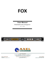
FOX
User Manual
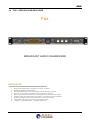
Broadcast Audio Changeover
(Rev. 3.1 ENG)
ENG
TABLE OF CONTENTS
1
INTRODUCTION ......................................................................................................................................................... 4
1.1
FOX VERSIONS AVAILABLE ........................................................................................................................................ 4
1.2
OPTION AVAILABLE ON FOX ...................................................................................................................................... 4
1.3
USE OF THIS MANUAL .............................................................................................................................................. 4
1.4
FOX – DEPLIANT AND BROCHURE .............................................................................................................................. 5
1.5
COMPARISON TABLE BETWEEN GENIUS D AND FOX ...................................................................................................... 7
1
SAFETY WARNINGS / ISTRUZIONI PER LA SICUREZZA ...................................................................................... 8
1.1
FOREWORD ....................................................................................................................................................... 8
2
SAFETY WARNINGS ................................................................................................................................................. 9
3
CONSIGNES DE SÉCURITÉ IMPORTANTES ......................................................................................................... 10
4
ISTRUZIONI IMPORTANTI PER LA SICUREZZA ................................................................................................... 11
5
WICHTIGE SICHERHEITSHINWEISE...................................................................................................................... 12
6
INSTRUCCIONES IMPORTANTES DE SEGURIDAD ............................................................................................. 14
7
UNPACKING AND INSPECTION ............................................................................................................................. 16
8
FIRST INSTALLATION RECOMMENDATIONS ...................................................................................................... 17
8.1
POWER SUPPLY CABLE ................................................................................................................................. 17
8.2
AC MAINS VOLTAGE SETTING (230 V / 115 V) ............................................................................................... 17
8.3
FUSE REPLACEMENT ..................................................................................................................................... 17
8.4
PROTECTION AGAINST LIGHTNING .............................................................................................................. 19
8.5
VENTILATION ................................................................................................................................................... 20
2
GENERAL DESCRIPTION OF FOX ......................................................................................................................... 21
2.1
FOX FRONT PANEL ................................................................................................................................................ 21
2.2
FOX REAR PANEL .................................................................................................................................................. 22
3
INSTALLATION AND USE OF THE FOX COMMAND SOFTWARE ....................................................................... 24
4
USE OF THE AUDIO CHANGEOVER ADDRESS MANAGER SOFTWARE .......................................................... 26
5
USE OF THE AUDIO CHANGEOVER REMOTER SOFTWARE ............................................................................. 27
5.1
ACCESS VIA USB AND SERIAL CONNECTION .............................................................................................................. 27
5.2
ACCESS THROUGH A TCP/IP CONNECTION ................................................................................................................ 28
6
MANAGEMENT OF FOX VIA SOFTWARE ............................................................................................................. 29
7
DETAIL OF AUDIO CHANGEOVER REMOTER ..................................................................................................... 30
7.1
DESCRIPTION OF FOX COMMAND SOFTWARE ............................................................................................................ 30
7.2
ANALOG AND DIGITAL INPUTS SECTION .................................................................................................................... 30
7.3
ANALOG OUTPUT AND DIGITAL OUTPUT SECTION ....................................................................................................... 31
7.4
SECTION GP INPUTS AND GP OUTPUTS ..................................................................................................................... 32
7.5
DTMF GENERATOR AND DECODER SECTION .............................................................................................................. 32
7.6
SECTION SETUP AND DISCONNECT .......................................................................................................................... 33
7.6.1 Description section Input -A Input -B (Analog Inputs) ....................................................................................................33
7.6.2 The Analog Input Denoiser module .................................................................................................................................35
7.6.3 Description section Input -C and Input -D (Digital Inputs).............................................................................................36
7.6.4 The Digital Input Denoiser module .................................................................................................................................38
7.7
OUTPUT SECTION .................................................................................................................................................. 39
7.8
SETTINGS SECTION ............................................................................................................................................... 41
7.8.1 DTMF Generator section ................................................................................................................................................41
7.8.2 Section DTMF Decoder ...................................................................................................................................................44
7.8.3 General Purpose I/O Section ...........................................................................................................................................45
7.8.4 Delay Section ...................................................................................................................................................................47
7.9
PROGRAM SETTINGS SECTION ................................................................................................................................ 48
8
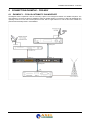
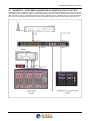
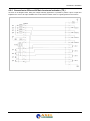
CONNECTION EXAMPLE - FOX MKII ..................................................................................................................... 49
8.1
EXAMPLE 1 – FOX AS AUTOMATIC CHANGEOVER ....................................................................................................... 49
8.2
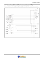
EXAMPLE 2 – FOX STUDIO CHANGEOVER ................................................................................................................. 50
8.3
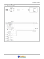
EXAMPLE 3 – FOX AS AUTOMATIC CHANGEOVER (FAULT) ANL ..................................................................................... 51
8.4
EXAMPLE 4 – FOX AS AUTOMATIC CHANGEOVER (FAULT) ANL-DGT .............................................................................. 52
8.5
EXAMPLE 5 – FOX COME CHANGEOVER AUTOMATICO (FAULT) DGT-DGT ...................................................................... 53
9
TECHNICAL APPENDIX .......................................................................................................................................... 54
9.1
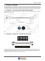
APPENDIX A - BALANCED AUDIO CONNECTION AND PINOUT ......................................................................................... 54
9.2
APPENDIX B - SERIAL DATA CONNECTION AND PINOUT ............................................................................................... 54
9.3
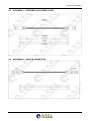
APPENDIX C - ETHERNET/LAN CONNECTIONS ............................................................................................................ 55
9.4
APPENDIX D - USB A/B CONNECTION ........................................................................................................................ 55
9.5
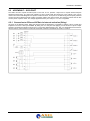
APPENDIX E – GPIO PORT....................................................................................................................................... 56
9.5.1 Connection to GPIn and GPOut via internal activation (Relay) .....................................................................................56
9.5.2 Connection to GPIn and GPOut via external activation (TTL) .......................................................................................57
9.5.3 Connection to GPIn and GPOut via external activation -2 (TTL) ...................................................................................58
9.5.4 Operative Example ..........................................................................................................................................................59
10
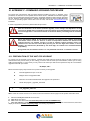
APPENDIX F - FIRMWARE UPGRADE PROCEDURE ....................................................................................... 60
10.1 PREPARATION OF THE UNIT FOR UPGRADE ............................................................................................................... 60
| INTRODUCTION
2
ENG
11
APPENDIX G – MIB DESCRIPTION AND ASCII PARSER ................................................................................. 62
11.1 MIB DESCRIPTION HANDLED BY FOX SNMP AGENT AND ASCII COMMANDS ..................................................................... 62
11.1.1
SNMP default configurations: .....................................................................................................................................62
11.1.2
ASCII default configurations: .....................................................................................................................................62
12
APPENDIX H - ASCII COMMANDS FOR FOX .................................................................................................... 70
12.1 OVERVIEW ........................................................................................................................................................... 70
12.2 COMMANDS .......................................................................................................................................................... 70
13
APPENDIX I – INTERFACE DJPRO TO A FOX MKII .......................................................................................... 72
14
APPENDIX L - DATA STRUCTURES ................................................................................................................. 74
15
TECHNICAL SPECIFICATION FOX ..................................................................................................................... 76
16
WEEE Directive – RAEE information ................................................................................................................. 77
17
WARRANTY ......................................................................................................................................................... 78
18
DECLARATION OF ROHS CONFORMITY .......................................................................................................... 78
19
FINAL NOTES AND AXL TECHNOLOGY CONTACTS ...................................................................................... 79
| INTRODUCTION
3
ENG
1 INTRODUCTION
1.1
1.2
1.3
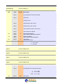
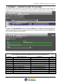
FOX VERSIONS AVAILABLE
CODE#
MODEL
COMMERCIAL DESCRIPTION
A110130000
FOX MKII
Digital audio changeover with 2 XLR analog inputs, 2
AES/EBU digital inputs, 1 XLR analog out, 1 AES/EBU
output. DTMF Encoder and decoder, USB and Serial port,
GPIN and GPOUT remote. 1u rack 19''space. Universal
power supply.
OPTION AVAILABLE ON FOX
CODE#
MODEL
A110130300
FOX-LAN
COMMERCIAL DESCRIPTION
Ethernet port for TCI/IP and UDP/IP connection, Rs232
(Parser ASCII) only for Fox.
USE OF THIS MANUAL
This manual can be used with the Fox MKII product. Certain features may be changed without notice.
| INTRODUCTION
4
ENG
FOX – DEPLIANT AND BROCHURE
1.4
Fox
BROADCAST AUDIO CHANGEOVER
HIGHLIGHTS
1.
2.
3.
4.
5.
6.
7.
8.
9.
Analogue and digital audio changeover, 4 inputs / 2 outputs
Broadcast digital audio DSP-based
4 analog/digital inputs and 2 analog/digital outputs with SRC converter
Any kind of commutation managed by the D/A and A/D converter
Input to output switch and fade with customizable time intervention and restore
Features audio: Denoiser Module, AGC Stage , input delay and Tone Generator
Graphic LCD display and front panel button for monitor and control
Internal DTMF Encoder e Decoder for automation system
1 Ethernet, 1 Rs232Serial port, 1 USB and GPIO Port
| INTRODUCTION
5
ENG
MAIN DESCRIPTION
Fox is a fully digital audio changeover, designed for Radio and TV broadcast marketplace.
Fox matches the most hi-end broadcast use requirements, with two analog inputs, two digital inputs, one analog output
and one digital output. All the inputs can be routed to a different audio output thanks to the A/D and D/A converter, so
that any kind of switch between different inputs can be managed.
Switching policies between inputs and outputs are fully user-configurable in order to suit individual requirements.
Furthermore Fox plays inside the entire audio chain the delicate role of program supervisor, thanks to an integrated
audio detector and the ability to generate an alarm when the nominal operating conditions are not met. When an alarm
rises, a switching command via GPO is provided. Fox presents in the front side a graphic LCD display that shows the
levels of analog and digital inputs and outputs and the alarms detected during the normal use.
The control software comes for free with Fox and allows the configuration of the timing and the policy of
intervention/recovery of switching, displaying levels of input and output signals and configure every working
parameter. It is also possible to save the data to a single device and create a database for all the Fox in operation into
the chain.
The process is based on DSP audio and the audio features included are: Denoiser, that eliminates unwanted noise on
the audio chain; the Delay module, a delay line applicable to a fully synchronous input in order to keep all audio sources.
During the process of allignement and calibration of the audio network, a Tone Generator generator with variable sample
frequency and amplitude is is provided with Fox and available on Analog and/or Digital outputs. Furthermore, a DTMF
encoder and a DTMF decoder with customizable strings, allow the remote management of automation systems.
The Fox’s rear panel is provided with XLR conneters, for balanced analog and digital AES/EBU signals. The outputs are
equipped with hardware bypass. In case of fault of the equipment the main analog input is directly routed to the analog
output and the main digital input is routed to the digital output.
In order to set up and use Fox, the connection to a Pc it is possible via RS232 remote serial port, USB connection and a
simply logic state via GPIO port with open collector and opto couplers that are representing the operational‘s states of
any alarms, along with command automation equipment using DTMF decoding strings. Optionally, it is possible to install
an Ethernet port and use the SNMP - TCP/IP protocol, in addiction to the web server installed on board that allows to
display the equipment status via a common web page.
Universal Power Supply 90-264Vac 47-63Hz that can operate in any region of the world. Fox takes up 1 rack unit
standard 19 "
| INTRODUCTION
6
ENG
1.5
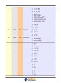
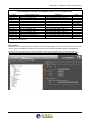
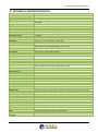
COMPARISON TABLE BETWEEN GENIUS D AND FOX
General Features
Audio Features
Audio Process
Input Mode
Fading mode
Waiting time / Return time
Working / Output Sequence
Tone Generator
Switch Command by Gpio/Serial
A.G.C – DeNoiser
DTMF Encoder / Decoder
Delay time – Settings
A/Dal and Digital to Analog
Converter
Front Panel operation
Automatic / Manual
LCD Panel
Level Input / Output
Input selection (Manual)
Audio Input and Output
Analog Input
Analog Output
Digital Input
Digital Output
Remote Control
GPIO Connector – Type
USB
Serial
Software Remoter
Ethernet Port /Web Server
Parser ASCII protocol
Genius D
Fox
120Mhz @ 24bit DSP-Based audio process
Stereo, MonoL, MonoR, MonoL+R,Swap Left/Right, Stereo Inverted Right, Stereo Inverted Left,
Swap inverted Right, Swap inverted Left
Fast switching, Slow fading, Normal fading, fast fading.
From 1sec to 120sec / From 1sec to 31sec
Off, Automatic, Manual, Manual by command Gpio
Off, Left=Right, onlyLeft, onlyRight @ 1 kHz
-
-
SubD 15p HD - 4x GP In opto coupled, 4x GP Out Open Collector opto isolated
1x USB – B Type EMI Filtered
2x Rs232 EMI Filtered
-
Rs232 by default
by option
Rs232 by default. TCP/IP and UDP by option
| INTRODUCTION
7
ENG
1 SAFETY WARNINGS / ISTRUZIONI PER LA SICUREZZA
SAFETY WARNINGS
CONSIGNES DE SÉCURITÉ IMPORTANTES
ISTRUZIONI IMPORTANTI PER LA SICUREZZA
WICHTIGE SICHERHEITSHINWEISE
INSTRUCCIONES IMPORTANTES DE SEGURIDAD
(Rel. 2.0)
1.1
FOREWORD
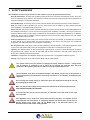
For your own safety and to avoid invalidation of the warranty all text marked with these Warning Symbols
should be read carefully.
Information in this manual is subject to change without notice and does not represent a commitment on the part of the
vendor.
The manufacturer shall not be liable for any loss or damage whatsoever arising from the use of information or any error
contained in this manual, or through any mis-operation or fault in hardware contained in the product.
It is recommended that all maintenance and service on the product should be carried out by the manufacturer or its
authorised agents. The manufacturer cannot accept any liability whatsoever for any loss or damage caused by service,
maintenance or repair by unauthorised personnel.
| SAFETY WARNINGS / ISTRUZIONI PER LA SICUREZZA
8
ENG
2 SAFETY WARNINGS
The installation and servicing instructions in this manual are for use by qualified personnel only.
- Read All Instructions. All safety and operating instructions must be read before operating the product. They also
must be retained for future reference, as it contains a number of useful hints for determining the best combination of
equipment settings for Yr particular application.
- Heed All Warnings. All warnings on the product and those listed in the operating instructions must be adhered to.
- Heat. This product must be situated away from any heat sources such as radiators or other products (including
power amplifiers or transmitters) that produce heat.
- Power Sources. This product must be operated from the type of power source indicated on the marking label and in
the installation instructions. If you are not sure of the type of power supplied to your facility, consult your local power
company. Make sure the AC main voltage corresponds to that indicated in the technical specifications. If a different
voltage (ex. 110/115 VAC) is available, open the equipment closure and set the voltage switch on the main supply
circuit, located behind the AC socket
- Power Cord Protection. Power supply cords must be routed so that they are not likely to be walked on nor pinched
by items placed upon or against them. Pay particular attention to the cords at AC wall plugs and convenience
receptacles, and at the point where the cord plugs into the product
- Use only with a cart, stand, tripod, bracket, or table specified by the manufacturer, or sold with the apparatus. When
a cart is used, use caution when moving the cart/apparatus combination to avoid injury from tip-over.
- Lightning. For added protection for this product during a lightning storm, or when it is left unattended and unused for
long periods of time, unplug it from the AC wall outlet and the audio connections. This will prevent damage to the
product due to lightning and power line surges
- Installation. Configuration and installation should only be carried out by a competent installation engineer
- Cabling. Using high quality wires, well protected. Make sure the cable integrity.
This symbol alerts you to the presence of dangerous voltage inside the closure – voltage which
may be sufficient to constitute a risk of shock. Do not perform any servicing other than that
contained in the operating instructions. Refer all servicing to qualified personnel
The exclamation point within an equilateral triangle is intended to alert the user to the presence of
important operating and maintenance (servicing) instructions in the literature accompanying the
appliance.
Do not change the voltage setting or replace the mains fuse without first turning the unit off
and unplugging the mains cord
Make sure the AC main voltage corresponds to that indicated in the technical specifications.
THIS APPARATUS MUST BE EARTHED !
To avoid risk of fire use the correct value fuse, as indicated on the label stuck on the right
side of the unit.
This apparatus uses a single pole mains switch and does therefore not separate the unit
completely from the mains power. To completely separate from mains power (in the event of
danger) unplug mains power cord. As the MAINS plug is the disconnect device, the
disconnect device shall remain readily operable.
| SAFETY WARNINGS
9
ENG
3
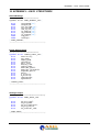
CONSIGNES DE SÉCURITÉ IMPORTANTES
- Lire ces consignes
- Conserver ces consignes
- Observer tous les avertissements
- Suivre toutes les consignes
- Ne pas utiliser cet appareil à proximité de l’eau
- Ne pas obstruer les ouvertures de ventilation. Installer en respectant les consignes du fabricant
- Ne pas installer à proximité d'une source de chaleur telle qu'un radiateur, une bouche de chaleur, un poêle ou
d'autres appareils (dont les amplificateurs) produisant de la chaleur.
- Ne pas annuler la sécurité de la fiche de terre, la troisième branche est destinée à la sécurité. Si la fiche fournie
ne s'adapte pas à la prise électrique, demander à un électricien de remplacer la prise hors normes.
- Protéger le cordon d'alimentation afin que personne ne marche dessus et que rien ne le pince, en particulier aux
fiches, aux prises de courant et au point de sortie de l’appareil
- Utiliser uniquement les accessoires spécifiés par le fabricant
- Utiliser uniquement avec un chariot, un support ou une table spécifié par le fabricant ou vendu avec l’appareil. Si
un chariot est utilisé, déplacer l’ensemble chariot–appareil avec précaution afin de ne pas le renverser, ce qui
pourrait entraîner des blessures
- Débrancher l’appareil pendant les orages ou quand il ne sera pas utilisé pendant longtemps.
- Confier toute réparation à du personnel qualifié. Des réparations sont nécessaires si l’appareil est endommagé
d’une façon quelconque, par exemple: cordon ou prise d’alimentation endommagé, liquide renversé ou objet tombé
à l’intérieur de l’appareil, exposition de l’appareil à la pluie ou à l’humidité, appareil qui ne marche pas normalement
ou que l’on a fait tomber.
- NE PAS exposer cet appareil aux égouttures et aux éclaboussements. Ne pas poser des objets contenant de
l'eau, comme des vases, sur l'appareil
Ce symbole indique la présence d'une tension dangereuse dans l'appareil constituant un risque de
choc électrique.
Ce symbole indique que la documentation fournie avec l'appareil contient des instructions
d'utilisation et d'entretien importantes.
Avant de modifier le commutateur de changement de tension ou replacer le fusible il faut
débrancher l’appareil de la prise électrique. Pendant son usage, l’appareil doit etre branchee à la
prise de terre
Utiliser le fusible principal AC avec le valeur qui est indiquée sur l'étiquette collée sur le coffret.
Assurez-vous que la tension principale AC correspond à celle indiquée dans les spécifications
techniques.
L’interrupteur d’alimentation interrompt un pôle du réseau d’alimentation excepté le conducteur
de terre de protection. En cas de danger, debrancher le cordon d'alimentation. Parce que la prise
du réseau de alimentation est utilisée comme dispositif de déconnexion, ce dispositif doit
demeuré aisément accessible
| CONSIGNES DE SÉCURITÉ IMPORTANTES
10
ENG
4 ISTRUZIONI IMPORTANTI PER LA SICUREZZA
- Leggere le presenti istruzioni
- Conservare queste istruzioni
- Osservare tutte le avvertenze
- Seguire scrupolosamente tutte le istruzioni
- Non usare questo apparecchio in prossimità di acqua
- Non ostruire alcuna apertura per il raffreddamento. Installare l’apparecchio seguendo le istruzioni
- Non installare l'apparecchio accanto a fonti di calore quali radiatori, aperture per l'afflusso di aria calda, forni o
altri apparecchi (amplificatori inclusi) che generino calore
- Non rimuovere il terminale di connessione a terra sul cordone di alimentazione: esso ha lo scopo di tutelare
l’incolumità dell’utilizzatore. Se la spina in dotazione non si adatta alla presa di corrente, rivolgersi ad un elettricista
per far eseguire le modifiche necessarie.
- Evitare di calpestare il cavo di alimentazione o di comprimerlo, specialmente in corrispondenza della spina e del
punto di inserzione sull’apparato.
- Utilizzare solo dispositivi di collegamento e gli accessori specificati dal produttore.
- Utilizzare l’apparecchio solo con un carrello, un sostegno, una staffa o un tavolo di tipo specificato dal produttore o
venduto insieme all’apparecchio. Se si utilizza un carrello, fare attenzione negli spostamenti per evitare infortuni
causati da ribaltamenti del carrello stesso.
- Scollegare l’apparecchio dalla presa di corrente durante i temporali o quando inutilizzato a lungo
- Per qualsiasi intervento, rivolgersi a personale di assistenza qualificato. È’ necessario intervenire sull’apparecchio
ogniqualvolta si verificano danneggiamenti di qualsiasi natura. Ad esempio, la spina o il cavo di alimentazione sono
danneggiati, è entrato liquido nell’apparecchio o sono caduti oggetti su di esso, l’apparecchio è stato esposto alla
pioggia o all’umidità, non funziona normalmente o è caduto.
- Non esporre a sgocciolamenti o spruzzi. Non appoggiare sull'apparecchio oggetti pieni di liquidi, ad esempio vasi
da fiori.
Questo simbolo indica la presenza di alta tensione all'interno dell'apparecchio, che comporta rischi
di scossa elettrica.
Questo simbolo indica la presenza di istruzioni importanti per l'uso e la manutenzione nella
documentazione in dotazione all'apparecchio.
Non sostituire il fusibile o cambiare la tensione di alimentazione senza aver prima scollegato il
cordone di alimentazione. L’APPARATO DEVE ESSERE CONNESSO A TERRA.
Sostituire il fusibile generale con uno di identico valore, come indicato sulla etichetta applicata
sul mobile dell’apparato
Assicurarsi che la tensione di rete corrisponda a quella per la quale è configurato
l’apparecchio
Questo apparato utilizza un interruttore di alimentazione di tipo unipolare e l’isolamento dalla
rete elettrica non è pertanto completo. Per ottenere un isolamento totale (ad esempio in caso di
pericolo), scollegare il cordone di alimentazione. Inoltre, poichè la spina di alimentazione è
utilizzata come dispositivo di sezionamento, essa deve restare facilmente raggiungibile
| ISTRUZIONI IMPORTANTI PER LA SICUREZZA
11
ENG
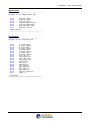
5 WICHTIGE SICHERHEITSHINWEISE
- Diese Hinweise LESEN
- Diese Hinweise AUFHEBEN
- Alle Warnhinweise BEACHTEN
- Alle Anweisungen BEFOLGEN
- Dieses Gerät NICHT in der Nähe von Wasser verwenden
- KEINE Lüftungsöffnungen verdecken. Gemäß den Anweisungen des Herstellers einbauen
- Nicht in der Nähe von Wärmequellen, wie Heizkörpern, Raumheizungen, Herden oder anderen Geräten
(einschließlich Verstärkern) installieren, die Wärme erzeugen
- Die Schutzfunktion des Schukosteckers NICHT umgehen. Bei Steckern für die USA gibt es polarisierte Stecker,
bei denen ein Leiter breiter als der andere ist; US-Stecker mit Erdung verfügen über einen dritten Schutzleiter. Bei
diesen Steckerausführungen dient der breitere Leiter bzw. der Schutzleiter Ihrer Sicherheit. Wenn der mitgelieferte
Stecker nicht in die Steckdose passt, einen Elektriker mit dem Austauschen der veralteten Steckdose beauftragen
- VERHINDERN, dass das Netzkabel gequetscht oder darauf getreten wird, insbesondere im Bereich der Stecker,
Netzsteckdosen und an der Austrittsstelle vom Gerät
- NUR das vom Hersteller angegebene Zubehör und entsprechende Zusatzgeräte verwenden.
- NUR in Verbindung mit einem vom Hersteller angegebenen oder mit dem Gerät verkauften Transportwagen, Stand,
Stativ, Träger oder Tisch verwenden. Wenn ein Transportwagen verwendet wird, beim Verschieben der
Transportwagen-Geräte- Einheit vorsichtig vorgehen, um Verletzungen durch Umkippen
- Das Netzkabel dieses Geräts während Gewittern oder bei längeren Stillstandszeiten aus der Steckdose
ABZIEHEN.
- Alle Reparatur- und Wartungsarbeiten von qualifiziertem Kundendienstpersonal DURCHFÜHREN LASSEN.
Kundendienst ist erforderlich, wenn das Gerät auf irgendwelche Weise beschädigt wurde, z.B. wenn das Netzkabel
oder der Netzstecker beschädigt wurden, wenn Flüssigkeiten in das Gerät verschüttet wurden oder Fremdkörper
hineinfielen, wenn das Gerät Regen oder Feuchtigkeit ausgesetzt war, nicht normal funktioniert oder fallen gelassen
wurde.
- Dieses Gerät vor Tropf- und Spritzwasser SCHÜTZEN. KEINE mit Wasser gefüllten Gegenstände wie zum
Beispiel Vasen auf das Gerät STELLEN.
Dieses Symbol zeigt an, dass gefährliche Spannungswerte, die ein Stromschlagrisiko darstellen,
innerhalb dieses Geräts auftreten.
Dieses Symbol zeigt an, dass das diesem Gerät beiliegende Handbuch wichtige Betriebs- und
Wartungsanweisungen enthält.
Vor Änderung der Netzspannung oder Sicherungswechsel Netzkabel trennen.
Das Gerät muss für den Betrieb geerdet werden.
Hauptsicherung nur mit einer gleichwertigen austauschen
(s. entsprechende Etikette).
Vor Einschalten Netzspannungseinstellung am Gerät überprüfen bzw. anpassen.
| WICHTIGE SICHERHEITSHINWEISE
12
ENG
Inpoliger Netzschalter. In Notfälle oder für Wartungsarbeiten Netzkabel trennen. Der Netzstecker
fungiert auch als Trennelement muss deshalb zugänglich bleiben
| WICHTIGE SICHERHEITSHINWEISE
13
ENG
6 INSTRUCCIONES IMPORTANTES DE SEGURIDAD
- LEA estas instrucciones
- CONSERVE estas instrucciones
- PRESTE ATENCION a todas las advertencias.
- SIGA todas las instrucciones
- NO utilice este aparato cerca del agua
- NO obstruya ninguna de las aberturas de ventilación.Instálese según lo indicado en las instrucciones del
fabricante
- No instale el aparato cerca de fuentes de calor tales como radiadores, registros de calefacción, estufas u otros
aparatos (incluyendo amplificadores) que produzcan calor
- NO anule la función de seguridad del enchufe polarizado o con clavija de puesta a tierra. Un enchufe polarizado
tiene dos patas, una más ancha que la otra. Un enchufe con puesta a tierra tiene dos patas y una tercera clavija con
puesta a tierra. La pata más ancha o la tercera clavija se proporciona para su seguridad. Si el toma corriente no es
del tipo apropiado para el enchufe, consulte a un electricista para que sustituya el toma corriente de estilo anticuado
- PROTEJA el cable eléctrico para evitar que personas lo pisen o estrujen, particularmente en sus enchufes, en los
toma corrientes y en el punto en el cual sale del aparato
- UTILICE únicamente los accesorios especificados por el fabricante
- UTILICESE únicamente con un carro, pedestal, escuadra o mesa del tipo especificado por el fabricante o vendido
con el aparato. Si se usa un carro, el mismo debe moverse con sumo cuidado para evitar que se vuelque con el
aparato
- DESENCHUFE el aparato durante las tormentas eléctricas, o si no va a ser utilizado por un lapso prolongado.
- TODA reparación debe ser llevada a cabo por técnicos calificados. El aparato requiere reparación si ha sufrido
cualquier tipo de daño, incluyendo los daños al cordón o enchufe eléctrico, si se derrama líquido sobre el aparato o
si caen objetos en su interior, si ha sido expuesto a la lluvia o la humedad, si no funciona de modo normal, o si se ha
caído.
- NO exponga este aparato a chorros o salpicaduras de líquidos. NO coloque objetos llenos con líquido, tales como
floreros, sobre el aparato.
Este símbolo indica que la unidad contiene niveles de voltaje peligrosos que representan un riesgo
de choques eléctricos.
Este símbolo indica que la literatura que acompaña a esta unidad contiene instrucciones
importantes de funcionamiento y mantenimiento.
Antes de cambiar la alimentacion de voltaje o de cambiar el fusible, desconecte el cable de
alimentacion. Para reducir el riesgo de descargas electricas, esta unidad debe ser conectada a
tierra.
Remplaze el fusible con lo mismo, que corresponde a lo indicado en el panel del equipo.
Antes de encender, controlar que la linea de alimentacion de voltaje corresponda a la indicada
| INSTRUCCIONES IMPORTANTES DE SEGURIDAD
14
ENG
El interruptor de alimentación es unipolar. En el caso de peligro, desconecte el cable de
alimentación. Porque la clavija de conexion a red sirve por la desconection de la unidad, la
clavija debe ser ubicada en proximidad de la unidad
| INSTRUCCIONES IMPORTANTES DE SEGURIDAD
15
UNPACKING AND INSPECTION
7 UNPACKING AND INSPECTION
Your equipment was packed carefully at the factory in a container designed to protect the unit during shipment.
Nevertheless, we recommend making a careful inspection of the shipping carton and the contents for any signs of
physical damage.
Damage & Claims
If damage is evident, do not discard the container or packing material. Contact your carrier immediately to file a claim for
damages. Customarily, the carrier requires you, the consignee, to make all damage claims. It will be helpful to retain the
shipping documents and the waybill number.
Save all packing materials! If You should ever have to ship the unti (e.g. for servicing), it is best to ship it in the
original carton with its packing materials because both the carton and packing material have been carefully designed to
protect the unit.
Under normal conditions no user maintenance or calibration are required. Internal links and preset controls may be set to
configure the unit during installation. Any service work required should be carried out by qualified service
personnel only.
We are able to offer further product support through our worldwide network of approved dealers and service agents.
To help us provide the most efficient service please would you keep a record of the unit serial
number, and date and place of purchase to be quoted in any communication regarding this
product.
The actual equipment Serial Number is indicated on the silver label stuck on the rear panel of the equipment closure.
Tools And Equipment Needed
Only standard technician’s tools are required to install this equipment.
| UNPACKING AND INSPECTION
16
FIRST INSTALLATION RECOMMENDATIONS
8 FIRST INSTALLATION RECOMMENDATIONS
8.1
POWER SUPPLY CABLE
A power supply cable of approx. 2 mt length is supplied with the device, which has a moulded IEC plug attached – this is
a legal requirement.
The type of plug for the power supply depends on the country in which it is delivered.
If for any reason, you need to use this appliance with a different plug, you should use the following wiring guidelines in
replacing the existing plug with the new one:
Earth
Neutral (N)
Live (L)
Green, or green and yellow
Blue
Brown
Supply cables should be laid in such a manner that one does not step or walk on them. They should not be squashed by
any objects.
THIS EQUIPMENT MUST BE EARTHED.
The chassis is always connected to mains earth to ensure your safety: check your mains wiring and earthing before
switching on.
8.2
AC MAINS VOLTAGE SETTING (230 V / 115 V)
BE SURE THAT THE UNIT IS SET TO THE CORRECT MAINS/LINE VOLTAGE FOR YOUR
COUNTRY BEFORE PLUGGING IT INTO THE WALL OUTLET !
The actual Mains voltage is indicated on the label stuck on the equipment closure. Should the type of power at the
operation location not be known, please contact your dealer or electricity company.
If, for some reason, the unit is to be operated at a mains input voltage which is different to that as supplied, you need to
switch the voltage selector on the right side of the unit. You also need to replace the AC main fuse, according to
information provided on the external label or on the Technical Specifications table at the end of this user manual.
CAUTION: TO REDUCE THE RISK OF ELECTRICAL SHOCK, ALWAYS DISCONNECT THE AC
MAINS CABLE BEFORE ALTERING THE CHANGE-OVER SWITCH. NO USER SERVICEABLE
PARTS INSIDE. REFER SERVICING TO QUALIFIED SERVICE PERSONNEL.
8.3
FUSE REPLACEMENT
The power supply socket has an integral fuse drawer containing the AC power fuse and a spare, both of the same value.
| FIRST INSTALLATION RECOMMENDATIONS
17
FIRST INSTALLATION RECOMMENDATIONS
BEFORE REPLACING THE POWER FUSE, MAKE SURE YOU HAVE THE RIGHT TYPE OF FUSE FOR
THE VOLTAGE TO BE PROTECTED.
USING WRONG FUSE TYPE WILL RESULT IN INSUFFICIENT PROTECTION.
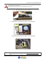
Make sure that the power is switched off and the power cable is disconnected from the equipment.
a. Open the upper iron cover using a screwdriver.
b. Replace the fuse located at the internal position – Power supply Type-1
c. Replace the fuse located at the internal position – Power supply Type-2
Perform the set-up under static control conditions. Static charges are likely to completely destroy one or
more of the CMOS semiconductors employed in the unit. Static damage will not be covered under
warranty.
| FIRST INSTALLATION RECOMMENDATIONS
18
FIRST INSTALLATION RECOMMENDATIONS
Basic damage prevention consists of minimizing generation, discharging any accumulated static charge
on your body and preventing that discharge from being sent to or through any electronic component.
Uninsulated dangerous voltage are inside the enclosure, voltage that may be sufficient to constitute a
risk of shock.
Always disconnect to AC Mains before removing the top cover
8.4
PROTECTION AGAINST LIGHTNING
When the upper iron cover is removed, a plastic transparent cover helps the user safety, to avoid from flashlight coming
from the switching power supply. After the power cord has been disconnected some parts of the power supply remain
electrically loaded for a lot of time.
Axel Technology suggest to don’t touch never this parts, and it is not responsible for human flash light or electrical burns.
Should the device be put out of action due to being struck by lightning or excess voltage, disconnect it
from the power supply without delay. Do not reconnect until the device has been checked. If in doubt
contact the technical support service.
Make sure there is suitable lighting protection to protect the device.
Alternatively you should disconnect all connectors from the device during a storm or when the device
is going to be unsupervised or not used for a longer period of time.
These measures will protect against damage by lightning or excess voltage.
| FIRST INSTALLATION RECOMMENDATIONS
19
FIRST INSTALLATION RECOMMENDATIONS
8.5
VENTILATION
The equipment will operate as a free-standing unit without requiring any special cooling arrangement.
However, slots and openings in the product are provided for ventilation. They ensure reliable operation of the product,
keeping it from overheating. These openings must not be blocked nor covered during operation.
YOU MUST LEAVE AT A MINIMUM ONE RACK UNIT OF EMPTY SPACE ABOVE THE EQUIPMENT TO ENHANCE
VENTILATION AND TO GET A LONGER EQUIPMENT LIFE.
| FIRST INSTALLATION RECOMMENDATIONS
20
GENERAL DESCRIPTION OF FOX
2 GENERAL DESCRIPTION OF FOX
2.1
N
O.
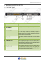
FOX FRONT PANEL
CONTROL NAME
FUNCTION
1
LCD DISPLAY
LCD display on two lines showing the status and operation of Fox. All
the technical parameters for each menu are displayed.
2
JOG-SHUTTLE
JogShuttle in order to be able to access the various navigation menus
and to make changes. Pressing the JogShuttle will confirm the
selection. Accessing the Menu, it is possible to fully configure the
machine for the operation mode on its analog output. All of these
parameters can also be set by control, configuration and Axel Audio
Changeover Remoter command software.
3
"ESC" KEY
Pressing this key cancels any changes made or you exit the selected
menu.
4
"ANALOG" KEY
Clicking the ANALOG key results in access to the selection Menu of
the Fox Analog output: through the sub-menu, it is possible to fully
configure the machine for the operation mode on its analog output. All
of these parameters can also be set by control, configuration and Axel
Audio Changeover Remoter command software.
5
"DIGITAL" KEY
Clicking the DIGITAL key results in access to the selection Menu of
the Fox Digital output: through the sub-menu, it is possible to fully
configure the machine for the operation mode on its Digital output. All
of these parameters can also be set by control, configuration and Axel
Audio Changeover Remoter command software.
| GENERAL DESCRIPTION OF FOX
21
GENERAL DESCRIPTION OF FOX
2.2
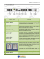
FOX REAR PANEL
N
O.
CONTROL NAME
FUNCTION
1
"DIGITAL" BLOCK
This part is dedicated to the connections for the inputs and the digital
output in AES/EBU format on XLR balanced connection. Digital input
1 is marked as 1C while input 2 is marked as 2D.
2
"USB" PORT
This port can be used to inspect and control the device remotely via a
normal PC. Before connecting this port you will need to install the
appliance control software inside the packaging.
+
ETHERNET PORT (opt)
3
-1 RS232 SERIAL
SERIAL PORT 1
+
-2 RS232 SERIAL
SERIAL PORT 2
4
"GPIO" PORT
Fox has an Rj45 Ethernet port mounted on board to inspect and
control the device. In addition, this port can be used for control of the
Web Browser and SNMP agent (optional).
Fox provides 2 serial ports for controlling the device via remote
control software. The operating parameters can be changed through
the Axel Audio Changeover Remoter command software, while
Axel Audio Changeover Address Manager allows the values of the
TCP/IP card, Target Name (or name of the device) and the access
password for SNMP switching to be set. It is also possible to set the
Target ID and to lock the front panel.
Serial Port 1 is also used to reprogram the firmware and to connect
to a 56K external analog modem (via telephone line remote
control). By default, the port speed is set at 38,400 bps.
15 poly high density female poly interface, on SubD connector. It
represents the logical state of Fox via the GPOut open collector,
while it provides the command of Fox via GPIn, thanks to the photo
couplers (optocouplers) installed on board.
The status of Fox is also visible from the software panel in the right
hand section of the software thanks to the part:
- GPInput
- GP Output
For information on the pinout of the Opto Interface port refer to the
Appendix at the end of this manual. See the specific section for the
operation of each GPI and GPO in the next few pages of this manual.
5
ANALOG OUTPUT
Fox ANALOG audio output, electronically balanced, on XLR
balanced stereo connector. I
| GENERAL DESCRIPTION OF FOX
22
GENERAL DESCRIPTION OF FOX
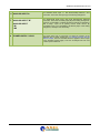
6
ANALOG INPUT-A
Fox ANALOG audio input -A with electronically balanced XLR
connection. This is the main input (A) of the analog changeover.
7
ANALOG INPUT "B"
Fox ANALOG-B audio input, with XLR electronically balanced
connection. This is the secondary input (B) of the analog changeover.
However, it is possible to consider this input as Primary as the DSP is
able to keep
input -B as primary source under control. By
"convention" input -A is considered to be Primary input of the analog
changeover, and input -B as secondary.
ANALOG INPUT
-BL
-BR
8
POWER SUPPLY LOCK
The power supply lock is composed of a switch for powering of the
appliance and a power supply plug. To change the fuse see the
relevant chapter, the fuse is located within the appliance at the height
of the switching power supply. The fuse is Delayed 230 Vac and
2.000 A equal to 2000 mA
| GENERAL DESCRIPTION OF FOX
23
INSTALLATION AND USE OF THE FOX COMMAND SOFTWARE
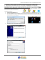
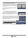
3 INSTALLATION AND USE OF THE FOX COMMAND SOFTWARE
The installation procedure of the Fox control software is described below. The program runs on all Windows platforms,
including Windows Xp sp3, Windows Vista and Windows 7 32-bit and Windows 7 64-bit and Windows 8 Pro 64bit. The
control software must be installed before connecting the devices to the USB port. To install the program follow the
instructions below using the program file from the original CD contained in the package with the device, or the file
downloaded from the Axel Technology website.
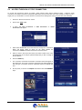
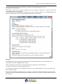
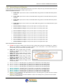
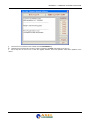
2. Installation Procedure:
1. Insert the CD into the player
2. Launch the SETUP.EXE application
a. It is however advisable to copy the application from the CD onto the system hard drive of the Pc from which you
are working, and to run execution of the same from the hard drive. Once execution has been launched, this
InstallShield Wizard screen will appear
3.
The following screen and press NEXT will appear on screen
4.
Fill in the information relating to the user:
| INSTALLATION AND USE OF THE FOX COMMAND SOFTWARE
24
INSTALLATION AND USE OF THE FOX COMMAND SOFTWARE
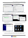
5.
Select the destination folder or leave it unchanged, press NEXT and then INSTALL
6.
The Software will begin installation of the application on the PC; during installation you will be asked to confirm
installation of the USB driver for connection to the Fox device.
11
11
11
7.
This screen will be displayed upon completion of installation, press Finish and then two new icons will be
created on the desktop:
a.
b.
8.
Axel Audio Changeover Remoter
Axl Audio Changeover Address Manager
At this point, it will be possible to use the applications in order to be able to manage the Fox devices. The
following chapters will provide explanations on the mode of connection, and the potentialities of the product.
| INSTALLATION AND USE OF THE FOX COMMAND SOFTWARE
25
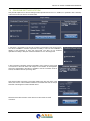
USE OF THE AUDIO CHANGEOVER ADDRESS MANAGER SOFTWARE
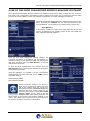
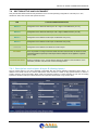
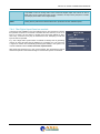
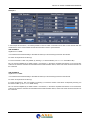
4 USE OF THE AUDIO CHANGEOVER ADDRESS MANAGER SOFTWARE
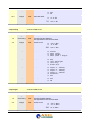
The Audio ChangeoverAddress Manager software is an application that is used to assign a Target ID to Fox, to lock the
front panel, to set a Target Name and possibly to apply an address to the TCP/IP port. To achieve this, both the Serial
port of the PC and the USB port can be used. Opening the application, the screen will display the following:
The Audio Changeover Address Manager is still disconnected from the Fox
device. By clicking the CONNECT key, the connection between PC and
Fox is established. For the COM port, the default values of the port are:
38,400 BPS 8-N-1
If, alternatively, a USB port is being used, simply select the relevant port
from the list assigned by the operating system (in this case VCOM Usb
Port). COM5 Port has been assigned.
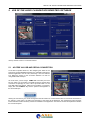
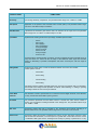
Once Fox and Audio Changeover Address Manager are
connected, the settings of the Ethernet port are displayed. To
change this data go to the appropriate fields and enter the port
data; when completed, press the SEND DATE key to send the
changes to the Fox device.
To check the actual implementation of the changes, press the
RELOAD DATE button, which requires refreshing of the program
and re-read the port values.
Using this application, it is possible to set the communication
Read Password and Write Password via the SNMP protocol.
The default setting is:
Read Password: public
Write Password: private
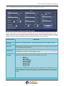
Various information relating to the device to
which you are connected is visible in the lower
part of the software above the control keys.
Data present includes "Connected Target" that
represents the device model to which you are
connected, in the photo a Fox and the installed
firmware release (v2.0.0). There is also the
Firmware Code which uniquely represents the
serial number of the firmware and hardware installed on the
device. This number may be required in the event of upgrade of
the device or for specific requests and customisation.
| USE OF THE AUDIO CHANGEOVER ADDRESS MANAGER SOFTWARE
26
USE OF THE AUDIO CHANGEOVER REMOTER SOFTWARE
5 USE OF THE AUDIO CHANGEOVER REMOTER SOFTWARE
Start-up window of the Fox command software
5.1
ACCESS VIA USB AND SERIAL CONNECTION
To be able to operate within Fox, after assigning the values of the
TCP/IP port via HybridAddress Manager, the AxelAudio Changeover
Remoter application must be used, launching it from the relevant
icon. Below the screen for the connection between Fox and PC
using USB Virtual serial port.
As can be seen, you are using a COM5 USB connection port of the
PC from which you are working. The USB connection and the serial
connection are promptly run, once a Pin-to-pin serial cable or a A-B
type USB cable, both present within the Fox package, is connected;
simply click the CONNECT key and the panel for management of
the device will open.
Clicking the Connect key, the Audio Changeover Remoter enters into communication with Fox and all the information in
the memory of the device, the status and operation of the same will be displayed. The management panel changes
format and offers all the necessary checks for installation of the apparatus. The various controls are explained in detail in
the next few chapters .
| USE OF THE AUDIO CHANGEOVER REMOTER SOFTWARE
27
USE OF THE AUDIO CHANGEOVER REMOTER SOFTWARE
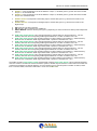
5.2
ACCESS THROUGH A TCP/IP CONNECTION
To access and manage the device via TCP/IP, simply perform these simple operations below. Unlike the serial
connection, the TCP/IP connection is extremely useful when you have more than one unit to manage. In doing so from a
single point, you will be able to connect with the Fox machines and manage the entire group remotely and individually.
1.
Press the " Remote Connection " button
2.
Click on the " EDIT" label
3.
A menu with 'New Connection' or 'Edit Connection' or 'Delete
Connection" will appear.
4.
Select "New Connection" and in the window to the right the "Connection
Editor" will appear clearly by which you can select whether the
connection is TCP/IP or Modem and set the Connection Name.
5.
Select a name in the Connection Name, and select TCP/IP, then in the
free fields enter the IP and port (default 10000) that you wish to assign to
the Fox device.
6.
Press the SAVE key.
7.
The connection saved with the relevant Connection Name will appear in
the central part, and in the Connection Information part will be displayed
both the type of connection (TCP/IP or Modem) and the IP address and
Port.
8.
At this point, to access via TCP/IP connection click the CONNECT
keys.
| USE OF THE AUDIO CHANGEOVER REMOTER SOFTWARE
28
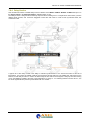
MANAGEMENT OF FOX VIA SOFTWARE
6 MANAGEMENT OF FOX VIA SOFTWARE
Axel Audio Changeover Remoter is the application that allows you to manage Fox both locally (using a serial connection
or USB connection) and remotely using TCP/IP network connection and from the Web page. With regard to the
monitoring functions, the front panel of the device also shows the levels of input and output and the primary functions
such as input/output sources and the levels of the Analog and Digital outputs.
Once logged in to Fox, the screen will display:
| MANAGEMENT OF FOX VIA SOFTWARE
29
DETAIL OF AUDIO CHANGEOVER REMOTER
7 DETAIL OF AUDIO CHANGEOVER REMOTER
7.1
DESCRIPTION OF FOX COMMAND SOFTWARE
There are essentially 5 parts to the Fox command software (Audio Changeover Remoter):
1.
2.
3.
4.
5.
7.2
Analog and Digital INPUTS section
Analog OUTPUT and Digital OUTPUT section
GP Section Inputs and GP Outputs section
DTMF Generator & Decoder section
Setup&Disconnect section
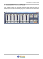
ANALOG AND DIGITAL INPUTS SECTION
The "inputs" section displays the input level of the four inputs of Fox and the status of the automatic gain control (AGC).
Fox allows you to connect two analog inputs and two digital inputs, divided as follows:
INPUT
TYPE
Input A
Analog A input identified as INPUT -A 1L 2R
Input B
Analog B input identified as INPUT -B BL BR
Input C
Digital C input identified as INPUT 1C
Input D
Digital D input identified as INPUT 2D
| DETAIL OF AUDIO CHANGEOVER REMOTER
30
DETAIL OF AUDIO CHANGEOVER REMOTER
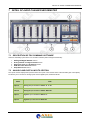
7.3
ANALOG OUTPUT AND DIGITAL OUTPUT SECTION
This part displays the level of the Analog output (A.OUTPUT) and Digital output (D.OUTPUT). In the presence of a
valid output level, the label changes into SRC INPUT x. For example, if input A is routed on the Analog output, then we
will find the words SRC INPUT A and the LED changes its colour from BLACK to GREEN.
The same thing happens with the Digital output. When an input is considered "valid" this is routed, with policies of
switching that can be decided, on the Digital output. The status changes from MUTED to SRC INPUTx exactly as for the
analog output. If input A is routed, then we will find the words SRC INPUT A instead of MUTED and the LED changes its
colour from BLACK to GREEN .
A feature of Fox is in fact the mounting on board of a powerful system of A/D and D/A converter that allows you to
convert an Analog input on a digital Output and a Digital input on an Analog output. This is to ensure maximum versatility
in use.
The labels placed under each input and output can be customised
with names that can be defined by the user. To achieve this, simply
open the Audio Changeover Address Manager and in the Channel
Names section assign each input / output a mnemonic name that will
indicate the destination or source of the audio signal concerned.
| DETAIL OF AUDIO CHANGEOVER REMOTER
31
DETAIL OF AUDIO CHANGEOVER REMOTER
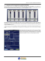
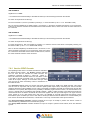
7.4
SECTION GP INPUTS AND GP OUTPUTS
In section GPInputs and GPOutputs are visible the status of the General
Purpose in Input and Output. The SubD 15poly HD female port on the back of
the device allows connections with the device. See the technical appendix for
connections and pinout. The purpose of this front panel is to show the status
of the various GP In and GP Out. The user cannot act to change the status of
the GP from this panel.
From the Fox front panel it is instead possible to see and learn the status of
the GP Inputs and GP Outputs by simply clicking the ANALOG or DIGITAL
key, and two lines show the status of
G-IN:
0-0-0-0
G-OUT: 0-0-0-0
7.5
DTMF GENERATOR AND DECODER SECTION
The DTMF Generator and Decoder section displays the three important Fox
operating parameters: Alarm, DTMF Generator and DTMF Decoder.
Alarm: This alarm is displayed when the Fox working condition is alarmed; an
example could be when all the switchings available are terminated, and there are
no more input sources to send on an output available.
DTMF Generator: this red indication represents the capacity of Fox to generate a
series of DTMF Tones, with user-customisable strings. The indication only represents
the ability of Fox to be able to generate DTMF tones, and not that Fox, when the
DTMF GENERATOR LED is lit, is generating DTMF tones. When the DTMF
Generator is ENABLED, this indication is lit. This control can be enabled or disabled
using Setup -> Settings. The subsequent chapters explain how to use in their entirety
the DTMF Generator and DTMF Decoder.
DTMF Decoder: this red indication represents the capacity of Fox
to recognise a series of DTMF Tones, with user-customisable
strings. The indication only represents the ability of Fox to be able to
decode the DTMF tones, and not that Fox, when the DTMF
GENERATOR LED is lit, is decoding DTMF tones.
Essentially, when the DTMF Decoder is ENABLED this indication is
lit. This control can be enabled or disabled using Setup -> Settings.
The subsequent chapters explain how to use in their entirety the DTMF Generator and DTMF Decoder.
| DETAIL OF AUDIO CHANGEOVER REMOTER
32
DETAIL OF AUDIO CHANGEOVER REMOTER
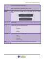
7.6
SECTION SETUP AND DISCONNECT
This part includes all the technical work parameters of Fox and the operating configurations. This setup is, in turn,
divided into Tabs, each of these with specific functions:
TAB
FUNCTION AND SPECIFICATION
INPUT A
Management of the ANALOG Audio input Left + Right on XLR Balanced ( IN 1-A.)
INPUT B
Management of the ANALOG Audio input Left + Right on Balanced XLR ( IN 1-B )
INPUT C
Management of the DIGITAL Audio Input on Balanced XLR ( IN C )
INPUT D
Management of the DIGITAL Audio Input on Balanced XLR ( IN D )
OUTPUTS
Management of the DIGITAL and ANALOG Audio Output
SETTINGS
Here it is possible to configure both the DTMF Generator that Decoder, the functions of the
individual General Purpose Input and Output and the Delay line to be applied to a specific
input or output.
PROGRAM SETTINGS
Display and selection of the control software settings in addition to the information on the
connection, firmware code, firmware version and target name.
7.6.1 Description section Input -A Input -B (Analog Inputs)
The two Analog inputs of Fox are individually configurable with the various operating parameters shown below. In
addition to the usual controls of a classic audio device, there are also a number of very special features to make it a
superior category device with Fading Mode, Delay and Denoiser module. For these features for both the two analog
inputs there is ONLY ONE Input Tab because the two inputs are identical and a copy of each other.
| DETAIL OF AUDIO CHANGEOVER REMOTER
33
DETAIL OF AUDIO CHANGEOVER REMOTER
CONTROL NAME
FUNCTION
Sensitivity
Input Analog Sensitivity Adjustment. The permitted values range from -12dBu to +12dBu
AGC Speed
Adjustment of the speed of the Automatic Gain Control (AGC). The permitted values range
from Off to +2.00 dB/s in steps of 0.05db /s
AGC Max Gain
It represents the maximum gain that the AGC can introduce at the input level. The permitted
values range from +1.0 dB to +12.0 dB in steps of 1.0 dB
Input Mode
Represents the working mode of the input stage. Possible options include:
-
-
Stereo
Mono (Left)
Mono (Right)
Mono (Left+Right)
Swap (Left/Right)
Stereo Inv Right
Stereo Inv Left
Swap Inv Right
Swap Inv Left
The Stereo-Mono classical modes of working are also completed by test functionality such as
Swap and Stereo Inv, where via INV the steps of the balanced audio signal are reversed
creating or eliminating a possible counterphase and where via Swap the Left from Right is
reversed.
Fading Mode
Represents the Fade mode, or mode of transition between one source and another.
Possible options include:
-
Fast Switch
-
Slow Fading
-
Normal Fading
-
Fast Fading
Fast Switch means a sudden and rapid switch from one source to another with a net switching.
Slow-Normal-Fast Fading instead represent an INITIAL fade switching, i.e. fading in opening
then fading towards the new source just switched.
Check Both
Channels
This checkbox is used to operate the Fox on both the Left and Right channels; if not selected,
Fox only controls the LEFT+RIGHT (mono) product.
Threshold
This parameter represents the level below which to consider the audio source invalid. In
practice, it is the minimum working threshold of the Changeover. The permitted values range
from -40dB to - 25dB
Wait Time
Changeover waiting time that is activated by the Threshold control before switching to a
different audio source. The permitted values range from 01 seconds to 120 seconds.
Return Time
Changeover waiting time before considering the primary source valid again. When the input
level exceeds the <threshold>, for a time equal to or greater than <return time> then the source
is considered valid again and the exchange from backup to primary is performed. It is very
| DETAIL OF AUDIO CHANGEOVER REMOTER
34
DETAIL OF AUDIO CHANGEOVER REMOTER
useful when the sources are defined as "dirty" and risk creating in output a continuous pingpong between Primary and Backup. This control allows a return time from 01 seconds to 31
seconds.
Analog Out
Priority
Represents the priority of the Audio source with respect to other audio sources. By introducing
in sequence the various inputs with respect to the Analog Output, a switching sequence is then
obtained which can be varied depending on requirements. The permitted values are 1-2-3-4
where 1 is the FIRST source, 2 the SECOND, 3 the THIRD, 4 the FOURTH.
OFF represents NON SWITCHING with regard to that source.
In each case switching takes place when the secondary sources (2-3-4) to which switching
must be performed, are considered valid, namely that physically there is an input audio, above
a certain level to be considered appropriate for broadcasting. Without this important control
upon switching, there would be a risk of backup audio source broadcast that is worse than the
primary source, while with this control inserted, the ability to perform switching to a Backup is
provided, given that the backup is better than the primary source that ceased to be valid.
Is it possible to send an Analog audio source toward the Digital output and then to send a
Digital audio source toward the Analog output; in addition, the Input Priority Sequence is visible
in the Output panel relative to the Analog Output.
Digital Out
Priority
Represents the priority of the Audio source with respect to other audio sources. By inserting in
sequence the various Inputs with respect to the Digital Output, a switching sequence is then
obtained which can be varied depending on requirements. The permitted values are 1-2-3-4
where 1 is the FISRT source, 2 the SECOND, 3 the THIRD, 4 the FOURTH.
OFF represents NON SWITCHING with regard to that source.
In each case switching takes place when the secondary sources (2-3-4) to which switching
must be performed, are considered valid, namely that physically there is an input audio , above
a certain level to be considered appropriate for broadcasting. Without this important control
upon switching, there would be a risk of backup audio source broadcast that is worse than the
primary source, while with this control inserted, the ability to perform switching to a Backup is
provided, given that the backup is better than the primary source that ceased to be valid.
Is it possible to send an Analog audio source toward the Digital output and at times to send a
Digital audio source towards the Analog output; in addition, the Input PrioritySequence is visible
in the Output panel relative to the Digital Output.
UNDO
Pressing this key restores the default values set in production for each individual panel.
7.6.2 The Analog Input Denoiser module
A Denoise is also available on the input settings screen. The Denoise is a feature
that provides the option to the device to minimise the noise that may occur on an
input. In so doing, if for one reason or another, there is an input defined as "dirty"
and "noisy", Fox tries in every way to minimise this noise, attempting to make the
input as clean as possible.
E.g.: with a large audio system where it is difficult to identify what is generating
noise on an input, this effect can be applied to try to minimise it. It is of course not
a "high tech" solution but undoubtedly provides great stability to the system. The
controls available include: On/Off, Threshold, Expander Ratio.
With On/Off the Denoiser may or may not be inserted, with Threshold the level at
which the Expander command must begin to increase the Dynamic is identified.
| DETAIL OF AUDIO CHANGEOVER REMOTER
35
DETAIL OF AUDIO CHANGEOVER REMOTER
7.6.3 Description section Input -C and Input -D (Digital Inputs)
The two Analog inputs of Fox are individually configurable with the various operating parameters shown below. In
addition to the usual controls of a classic audio device, there are also a number of very special features to make it a
superior category device with Fading Mode, Delay and Denoiser module For these features for both the two analog
inputs there is ONLY ONE Input Tab because the two inputs are identical and a copy of each other.
CONTROL NAME
FUNCTION
Sensitivity
Adjustment of Input Digital sensitivity The permitted values range from -24 dBFs to 0.0 dBFs
AGC Speed
Adjustment of the speed of the Automatic Gain Control (AGC). The permitted values range from
Off to +2.00 dB/s in steps of 0.05db /s
AGC Max Gain
It represents the maximum gain that the AGC can introduce at the input level. The permitted
values range from +1.0 dB to +12.0 dB in steps of 1.0 dB
Input Mode
Represents the working mode of the input stage. Possible options include:
-
-
Stereo
Mono (Left)
Mono (Right)
Mono (Left+Right)
Swap (Left/Right)
Stereo Inv Right
Stereo Inv Left
Swap Inv Right
Swap Inv Left
The Stereo-Mono classical mode of working are also completed by test functionality such as
Swap and Stereo Inv, where via INV, the steps of the balanced audio signal are reversed
creating or eliminating a possible counterphase and where via Swap the Left from Right is
reversed.
| DETAIL OF AUDIO CHANGEOVER REMOTER
36
DETAIL OF AUDIO CHANGEOVER REMOTER
Fading Mode
Represents the Fade mode, or mode of transition between one source and another.
Possible options include:
-
Fast Switch
-
Slow Fading
-
Normal Fading
-
Fast Fading
Fast Switch means a sudden and rapid switch from one source to another with a net switching.
Slow-Normal-Fast Fading instead represent an INITIAL fade switching, i.e. fading in opening then
fading towards the new source just switched.
Check Both
Channels
This checkbox is used to operate the Fox on both the Left and Right channels; if not selected
Fox only controls the LEFT+RIGHT (mono) product.
Threshold
This parameter represents the level below which to consider the audio source invalid. In
practice, it is the minimum working threshold of the Changeover. The permitted values range
from -40dB to +12dB
Wait Time
Changeover waiting time that is activated by the Threshold control before switching to a different
audio source. The permitted values range from 01 seconds to 120 seconds.
Return Time
Changeover waiting time before considering the primary source valid again. When the input level
exceeds the <threshold>, for a time equal to or greater than <return time> then the source is
considered valid again and the exchange from backup to primary is performed. It is very useful
when the sources are defined as "dirty" and risk creating in output a continuous ping-pong
between Primary and Backup. This control allows a return time from 01 seconds to 31 seconds.
Analog Out
Priority
Represents the priority of the Audio source with respect to other audio sources. By inserting in
sequence the various Inputs with respect to the Analog Output a switching sequence is then
obtained which can be varied depending on requirements. The permitted values are 1-2-3-4
where 1 is the FISRT source, 2 the SECOND, 3 the THIRD, 4 the FOURTH.
OFF represents NON SWITCHING with regard to that source.
In each case switching takes place when the secondary sources (2-3-4) to which switching must
be performed, are considered valid, namely that physically there is an input audio, above a
certain level to be considered appropriate for broadcasting. Without this important control upon
switching, there would be a risk of backup audio source broadcast that is worse than the primary
source, while with this control inserted, the ability to perform switching to a Backup is provided,
given that the backup is better than the primary source that ceased to be valid.
Is it possible to send an Analog audio source toward the Digital output and at times to send a
Digital audio source toward the Analog output; in addition, the Input Priority Sequence is visible in
the Output panel relative to the Analog Output.
Digital Out
Priority
Represents the priority of the Audio source with respect to other audio sources. By inserting in
sequence the various Inputs with respect to the Digital Output, a switching sequence is then
obtained which can be varied depending on requirements. The permitted values are 1-2-3-4
where 1 is the FISRT source, 2 the SECOND, 3 the THIRD, 4 the FOURTH.
OFF represents NON SWITCHING with regard to that source.
In each case switching takes place when the secondary sources (2-3-4) to which switching must
be performed, are considered valid, namely that physically there is an input audio , above a
certain level to be considered appropriate for broadcasting. Without this important control upon
switching, there would be a risk of backup audio source broadcast that is worse than the primary
source, while with this control inserted, the ability to perform switching to a Backup is provided,
given that the backup is better than the primary source that ceased to be valid.
| DETAIL OF AUDIO CHANGEOVER REMOTER
37
DETAIL OF AUDIO CHANGEOVER REMOTER
Is it possible to send an Analog audio source toward the Digital output and at times to send a
Digital audio source towards the Analog output; in addition, the Input Priority Sequence is visible
in the Output panel relative to the Digital Output.
UNDO
Pressing this key restores the default values set in production for each individual panel.
7.6.4 The Digital Input Denoiser module
A Denoise is also available on the input settings screen. The Denoise is a feature
that provides the option to the device to minimise the noise that may occur on an
input. In so doing, if for one reason or another, there is an input defined as "dirty"
and "noisy", Fox tries in every way to minimise this noise, attempting to make the
input as clean as possible.
E.g.: with a large audio system where it is difficult to identify what is generating
noise on an input, this effect can be applied to try to minimise it. It is of course not
a "high tech" solution but undoubtedly provides great stability to the system. The
controls available include: On/Off, Threshold, Expander Ratio.
With On/Off the Denoiser may or may not be inserted, with Threshold the level at
which the Expander command must begin to increase the Dynamic is identified.
| DETAIL OF AUDIO CHANGEOVER REMOTER
38
DETAIL OF AUDIO CHANGEOVER REMOTER
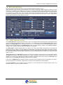
7.7
OUTPUT SECTION
Once the inputs have been set and programmed, in the part dedicated to Outputs all that remains is to set a number of
technical values such as the level of output and the ability to accept external commands. This software part is separated
into two areas, the first is the Digital output while the second represents the Analog audio output. The table below the
photograph of the Fox screen shows in detail the possible settings.
FUNCTION
CONTROL NAME
Nominal Output
Level
It represents the nominal output level of the Analog and Digital signal. The permitted values range
from -24.0 dBFs to 0.0dBFs for the Digital part while they range from -10.0 dBu to +14.0 dBu for
the Analog part.
Frequency
Sampling frequency of the Digital signal in use. The permitted values are:
Resolution
-
32 kHz
-
44.1 kHz
-
48.0 kHz
-
64.0 kHz
-
88.2 kHz
-
96 kHz
Resolution value of the of the Digital signal in use. The permitted values are:
-
Source
16 bit
20 bit
24 bit
It represents which INPUT source must be sent to the Digital or Analog output. The available
values include
InputA / InputB / InputC / InputD / Automatic / Off
By entering the Automatic value, the use of the Audio Changeover between Inputs is also
implicitly inserted and thus also respecting of the side Input Priority Sequence. Entering instead an
| DETAIL OF AUDIO CHANGEOVER REMOTER
39
DETAIL OF AUDIO CHANGEOVER REMOTER
Input fixed value, the Audio Changeover is implicitly disabled and there continues to be a single
fixed source towards the Analog or Digital output.
As such, to change an input with respect to an output, commands (GPIn or SNMP) can be sent to
the device, assuming that the Accept ExtCmds checkbox is enabled.
Input Priority
Sequence
It represents the sequence in which the Audio Changeover is set. The setting of each individual
priority occurs from every single INPUT, this box is only to display of the order of assigned
priorities.
Digital Output priority sequence
Analog Output priority sequence
Accepts ExtCmds
If flagged, it enables change of the input sources depending on receipt of external commands such
as GPIn or SNMP.
Generator
If enabled, it enters a 100 Hz / 0 dBm signal on the selected output, very useful when having to
calibrate or test an audio chain. Possible options include:
Output Mode
UNDO
-
Off
-
Left and Right
-
Only Left
-
Only Right
Selection of the output mode, the possibilities include:
-
Stereo
-
Mono (Left)
-
Mono (Right)
-
Mono (Left + Right)
Clicking this key restores the default values set in production for each individual panel.
| DETAIL OF AUDIO CHANGEOVER REMOTER
40
DETAIL OF AUDIO CHANGEOVER REMOTER
7.8
SETTINGS SECTION
This section displays all the technical and working parameters related to features such as:
DTMF Generator, DTMF Decoder, General Purpose I/O and Delay. Specifically, DTMF Generator is defined as all the
controls for the generation part of DTMF tones to be sent to the Analog and Digital output. DTMF Decoder instead refers
to the checks for the recognition of DTMF tones received on a particular input. The General Purpose I/O section defines
the procedures for operation both of the General Purpose Input and General Purpose Output. The Delay section
concerns the possibility for Fox to introduce a delay line on a particular input or a given output in order to keep different
sources aligned with arrivals offset against each other.
7.8.1 DTMF Generator section
The “Cmd by GP Input" checkbox indicates the Fox option of accepting and thus encoding DTMF commands by closure
of the various GPIn. An example as shown in the photo, if it is included in the section General Purpose I/O to section
GP Inp 1, the DTMF CMD3 section, when Input 1 goes to 1 (i.e., is activated) then on the analog and digital output the
DTMF command corresponding to the CmdString #3 will start. As stated, all this is subject to the "Cmd by GP Input "
checkbox that if enabled makes the actions described above operational.
The "Mixed Mode" checkbox indicates that Fox is able to mix, mix the audio DTMF commands that it was previously
managing in input. In doing so, it is also possible to add the DTMF commands to the Fox audio input. Where you don't
wish to add the DTMF commands to the audio from the Fox input, simply de-select this checkbox. In this case however
the sound is first stopped, then the DTMF commands are sent and subsequently upon sending of the strings the audio
returns in output.
"Analog Out Level" and “Dig.Outlevel” mean the level at which the DTMF tones are issued on the respective Analog
and Digital audio outputs. The recommended level is -10 dB in a situation of mixed audio. The Fox machine is able to
operate up to a minimum of -30 dB, but the conditions required to obtain these levels are by using the "Speed Slow" and
activating on Fox the 'Decode Low Levels" checkbox located in reception.
In the section " DTMF Speed' it is possible to select the speed at which the DTMF strings are transmitted. As is known:
more robust operation is obtained by using the Slow commands and the DecodeLowLevels disabled.
The "Test Command" section instead serves to manually run a Test command to the Analog or Digital outputs. It is
possible to select one of the four DTMF commands.
| DETAIL OF AUDIO CHANGEOVER REMOTER
41
DETAIL OF AUDIO CHANGEOVER REMOTER
The photo below shows the protocol of the DTMF commands; to open this help press the "?" key
The string format is AAA-OC-RR
Where AAA is meant as the command destination that can be toward a single Fox or a group of Foxes (see
CommandString Help on the next page).
OC means OUTPUT and COMMAND, the command can be sent to the Analog output (1) or to the Digital output (2) or
directly to the GPO via the (3). C means the COMMANDS related to the GPO output.
Example 1:
The example above, that is the tutorial included within the command software both of Fox and of Genius D, is an
example of the command * 401206 and what it means:
* 40 = Command sent to all the Foxes / Genius D whose last two digits are 40 in their Address ID.
1 = Action to be carried out on the ANALOG OUTPUT (1)
2 = command to be carried out on the variable shown above, i.e. on the analog output, thus C=2 as a result input -B is
sent to the Analog output.
06 = 06 minutes multiplied by x5 stable minutes = 30 minutes, i.e. the above requested command is run for 30 minutes,
at the end of which the command is terminated and the initial condition returns, which is the same as before execution of
the command.
| DETAIL OF AUDIO CHANGEOVER REMOTER
42
DETAIL OF AUDIO CHANGEOVER REMOTER
Example 2:
In the example shown above, it is instead possible to see how DTMF commands can be sent to other devices both Fox
and Genius D, and to use the DTMF Encoder and Decoder to close or open GPOUTs.
CMD STRING #1
Significance of ***3101:
***= Command sent indiscriminately to all DTMF decoders (Fox and Genius (D) entered in the network.
3 = Action to be performed on GPO (3).
1 = if the command is 3 then it is possible, by entering 1, to close the GPO1( If O=3 -> C=1: Set DTMF FUN1).
01 = 01 minutes multiplied by x5 stable minutes = 05 minutes, i.e. the above requested command is run for 05 minutes,
at the end of which the command is terminated and the initial condition returns, which is the same as before execution of
the command.
CMD STRING #2
Significance of ***3201:
***= Command sent indiscriminately to all DTMF decoders (Fox and Genius (D) entered in the network.
3 = Action to be performed on GPO (3)
2 = if the command is 3, then it is possible, by entering 2, to reset the closure of the GPO1 consequently restoring it to
the initial condition ( If O=3 -> C=2: DTMF FUN1).
01 = 01 minutes multiplied by x5 stable minutes = 05 minutes, i.e. the above requested command is run for 05 minutes,
at the end of which the command is terminated and the initial condition returns, which is the same as before execution of
the command.
| DETAIL OF AUDIO CHANGEOVER REMOTER
43
DETAIL OF AUDIO CHANGEOVER REMOTER
CMD STRING #3
Significance of ***3301:
***= Command sent indiscriminately to all DTMF decoders (Fox and Genius (D) entered in the network
3 = Action to be performed on GPO (3)
3 = if the command is 3, then it is possible, by entering 2, to close the GPO2 ( If O=3 -> C=3: Set DTMF FUN2)
01 = 01 minutes multiplied by x5 stable minutes = 05 minutes, i.e. the above requested command is run for 05 minutes,
at the end of which the command is terminated and the initial condition returns, which is the same as before execution of
the command.
CMD STRING #4
Significance of ***3401:
***= Command sent indiscriminately to all DTMF decoders (Fox and Genius (D) entered in the network
3 = Action to be performed on GPO (3)
4 = If the command is 3, then it is possible, by inserting 4, to reset the closure of the GPO2 consequently restoring it to
the initial condition ( If O=3 -> C=4: Reset DTMF FUN2).
01 = 01 minutes multiplied by x5 stable minutes = 05 minutes, i.e. the
above requested command is run for 05 minutes, at the end of which
the command is terminated and the initial condition returns, which is
the same as before execution of the command.
7.8.2 Section DTMF Decoder
The operating modes of the Fox DTMF Decoder are selected in
the DTMF Decoder section. The 'Enable" checkbox indicates
that Fox must also be activated as DTMF Decoder. The
subsection composed of INPUT A - INPUT B - INPUT C INPUT D check boxes indicates where Fox must listen in order
to be able to decode the DTMF tones. It is also possible to
select all the inputs, although we recommend that you select
only one input to avoid unnecessary noises or interference on
the DTMF decoder.
The "DecodeLow Level" check box accepts and sends signals lower than -20dB to the DTMF decoder. This control
must be used in conjunction with the slow command speed (DTMF Speed Slow). Activating this control increases
reception sensitivity but the probability of error is also consequently increased if the DTMF tone reaches the decoder with
interference or too quickly with respect to the possibility of decoding. Again with this control, it is recommended not to
use it if it signals that are considered high (typically between -15dB to -10dB) are being used while these levels are
recommended when the DTMF commands are sent mixed together with the input audio signal. This signal could be
music, speech or of any other nature and in this case, it is advisable to work with high levels and Normal or Slow
transmission speed. If instead you want to work with low levels (and therefore with the Decode Low Levels enabled), the
tone must be sent WITHOUT mixed audio, or audio that is "voice only" and associate a low speed command.
The "Accept Switching Comands" checkbox enables the Fox upon its receipt to perform the various controls of
channel Switching, otherwise these commands are ignored.
The "Accept GPO Comands" checkbox enables Fox upon its receipt to perform remote GPOs, which are otherwise
ignored.
| DETAIL OF AUDIO CHANGEOVER REMOTER
44
DETAIL OF AUDIO CHANGEOVER REMOTER
7.8.3 General Purpose I/O Section
In this section are set the features of General Purpose both in Input and in Output. GP Inp means the features that must
be performed by Fox upon receipt of a GPIn on port 1,2,3 or 4.
These are possible for the GP In:
a.
DTMF CMD1: Upon closure of GPIn 1 the DTMF CMD1 string present in the DTMF Generator panel is
launched.
b.
DTMF CMD2: Upon closure of GPIn 2 the DTMF CMD1 string present in the DTMF Generator panel is
launched.
c.
DTMF CMD3: Upon closure of GPIn 3 the DTMF CMD1 string present in the DTMF Generator panel is
launched.
d.
DTMF CMD4: Upon closure of GPIn 4 the DTMF CMD1 string present in the DTMF Generator panel
is launched.
e.
INP A ON ANOUT: Changes of the input with respect to the Analog audio output
f.
INP B ON ANOUT: Changes of the input with respect to the Analog audio output
g.
INP C ON ANOUT: Changes of the input with respect to the Analog audio output
h.
INP D ON ANOUT: Changes of the input with respect to the Analog audio output
i.
INP A ON DIGOUT: Changes of the input with respect to the Digital audio output
j.
INP B ON DIGOUT: Changes of the input with respect to the Digital audio output
k.
INP C ON DIGOUT: Changes of the input with respect to the Digital audio output
l.
INP D ON DIGOUT: Changes of the input with respect to the Digital audio output
These are possible for the GP Out:
a.
ALARM: the condition of Alarm occurs when Fox has not been able to perform the switchings set. Where a
switch is not effected, Fox displays the Alarm indication on the front panel; in the control software the
corresponding LED is lit and the GPO is possibly closed.
b.
DTMF FUN1: When a
decoded, it coincides
corresponding GPO.
DTMF FUN2: When a
decoded, it coincides
corresponding GPO.
DTMF FUN3: When a
decoded, it coincides
corresponding GPO.
DTMF FUN4: When a
decoded, it coincides
corresponding GPO.
c.
d.
e.
DTMF string is correctly
with the closing of the
DTMF string is correctly
with the closing of the
DTMF string is correctly
with the closing of the
DTMF string is correctly
with the closing of the
f.
g.
h.
i.
INPUT A ON ANOUT: This GPO goes to (1) when input -A is valid and is on the Analog output
INPUT B ON ANOUT: This GPO goes to (1) when input -B is valid and is on the Analog output
INPUT C ON ANOUT: This GPO goes to (1) when input -C is valid and is on the Analog output
INPUT D ON ANOUT: This GPO goes to (1) when input -D is valid and is on the Analog output
j.
k.
l.
m.
n.
INPUT A ON DIGOUT: This GPO goes to (1) when input -A is valid and is on the Digital output
INPUT B ON ANOUT: This GPO goes to (1) when input -B is valid and is on the Digital output
INPUT C ON ANOUT: This GPO goes to (1) when input -C is valid and is on the Digital output
INPUT D ON ANOUT: This GPO goes to (1) when input -D is valid and is on the Digital output
SIGNAL A: Only corresponds to the Audio-Detector of input -A, this GPO goes to (1) when the source located
at input -A is considered valid.
SIGNAL B: Only corresponds to the Audio-Detector of Input -B, this GPO goes to (1) when the source located
at input -B is considered valid.
o.
| DETAIL OF AUDIO CHANGEOVER REMOTER
45
DETAIL OF AUDIO CHANGEOVER REMOTER
p.
q.
r.
s.
t.
u.
v.
SIGNAL C: Only corresponds to the Audio-Detector of Input -C, this GPO goes to (1) when the source located
at input -C is considered valid.
SIGNAL D: Only corresponds to the Audio-Detector of Input -D, this GPO goes to (1) when the source located
at input -D is considered valid.
SIGNAL AN OUT: Corresponds to the Analog output, and the GPO goes to (1) when there is audio on the
Analog output.
SIGNAL DIG OUT: Corresponds to the Digital output, and the GPO goes to (1) when there is audio on the
Digital output.
OFF: GPO Off, not able to operate
ON: GPO On, GPO continues to be enabled (1)
GPIN 2 MIRROR: Performs the step from (0) to (1) depending on what is received on GPIN (in this example the
GPIN 2)
w. DTMF FUN1 START PULSE: This command performs a pulse of 300ms on the door GPOut (1 - 300 ms
duration) whenever the corresponding DTMF signal FUNCTION -1 makes a transition from 0 to 1.
x. DTMF FUN1 STOP PULSE: This command performs a pulse of 300ms on port GPOut (0 - 300ms duration)
whenever the consideration DTMF signal FUNCTION -1 performs a transition from 1 to 0.
y. DTMF FUN2 START PULSE: This command performs a pulse of 300ms on the door GPOut (1 - 300 ms
duration) whenever the corresponding DTMF signal FUNCTION -2 makes a transition from 0 to 1.
z. DTMF FUN2 STOP PULSE: This command performs a pulse of 300ms on port GPOut (0 - 300ms duration)
whenever the consideration DTMF signal FUNCTION -2 performs a transition from 1 to 0.
aa. DTMF FUN3 START PULSE: This command performs a pulse of 300ms on the door GPOut (1 - 300 ms
duration) whenever the corresponding DTMF signal FUNCTION -3 makes a transition from 0 to 1.
bb. DTMF FUN3 STOP PULSE: This command performs a pulse of 300ms on port GPOut (0 - 300ms duration)
whenever the consideration DTMF signal FUNCTION -3 performs a transition from 1 to 0.
cc. DTMF FUN4 START PULSE: This command performs a pulse of 300ms on the door GPOut (1 - 300 ms
duration) whenever the corresponding DTMF signal FUNCTION -4 makes a transition from 0 to 1.
dd. DTMF FUN4 STOP PULSE: This command performs a pulse of 300ms on port GPOut (0 - 300ms duration)
whenever the consideration DTMF signal FUNCTION -4 performs a transition from 1 to 0.
The DTMF command FUNx START PULSE and the DTMF command FUNx STOP PULSE: This is extremely important
when one needs to command the remote automation systems, whether they be television or radio and/or the control and
command of transmitters via remote telemetry, and one needs to have a command pulse of duration of 300ms, rather
than a command stable, which then resets after "n" time as for DTMF FUNx
| DETAIL OF AUDIO CHANGEOVER REMOTER
46
DETAIL OF AUDIO CHANGEOVER REMOTER
7.8.4 Delay Section
This command introduces a variable delay of 0ms to 1800ms on the INPUT -A INPUT -B INPUT -C INPUT -D input or on
the Analog output or on the Digital output in individual steps of 1ms.
The ability to insert a delay becomes extremely important when installing Fox in a complex audio chain where you have
different audio sources, and these are staggered in time with each other. In order to then synchronise them, this
command is used.
A typical use of this delay module is the ability to maintain synchronisation of two sources that arrive at the site of
transmission, one of these by satellite, while the second arrives via land audio line. The satellite has, with respect to the
land line, a total delay of 510ms. In order to be able to keep the two audio sources aligned, a delay equal to the incoming
one on the satellite is applied to the input of the terrestrial line. In doing so - in a switching between sources via Fox -, the
two audio signals will be in perfect synchronisation with one another.
| DETAIL OF AUDIO CHANGEOVER REMOTER
47
DETAIL OF AUDIO CHANGEOVER REMOTER
7.9
PROGRAM SETTINGS SECTION
This part will explain how to see and manage all the optional features of Fox. In addition, it is possible to see a summary
of the functions and the device connection data.
In this panel, it is possible to see and set a number of parameters of the FOX program.
The "Show PeakMeter" checkbox represents the ability to also see the PeakMeter in
displays of the indications of input and output level. The "Stay on top" checkbox
represents the ability to keep the command software of Fox in the foreground.
In this Connection Information panel it is possible to see a summary of the mode
of connection of the FOX device with respect to the software for management
and control. Specifically to the side it is possible to see the connection mode in
TCP/IP, the address and the port being used.
This panel provides a summary of the FOX model being used, the name of the
device, the version of the Firmware installed on the device DSP and the unique
Firmware code assigned to each individual device.
Panel devoted to disconnection of the device from the TCP/IP or Serial
connection.
| DETAIL OF AUDIO CHANGEOVER REMOTER
48
CONNECTION EXAMPLE - FOX MKII
8 CONNECTION EXAMPLE - FOX MKII
8.1
EXAMPLE 1 – FOX AS AUTOMATIC CHANGEOVER
The diagram below is explained a case of connecting a place in Fox changeover between two satellite receptions. The
main satellite is connected to 'INPUT-A (Satellite-A) while the satellite backup is connected to' INPUT-B (Satellite-B) The
operating mode Fox in this case must be placed in AUTO, that he might make that in case of fault of the satellite-A is
performed automatically switch to the Satellite-B
| CONNECTION EXAMPLE - FOX MKII
49
CONNECTION EXAMPLE - FOX MKII
8.2
EXAMPLE 2 – FOX STUDIO CHANGEOVER
The diagram below explaines a case of connecting a place in the Fox studios shift mode: This mode is used when within
an issuer needs to broadcast a study of airing (OnAir) rather than a second study (Production) in analog mode.
It should be made very carefully since, if it is left in the Fox AUTOMATIC, when the first study (Main OnAir) no longer
presents audio, switching is performed on the second study (Production or Emergency OnAir) This if and only if l 'input-B
of the study Production presents an audio signal VALID and above the Threeshold. E 'can also use the GPIO port to
send a command through the use of a GPIN to forcibly perform the switching between the studies.
| CONNECTION EXAMPLE - FOX MKII
50
CONNECTION EXAMPLE - FOX MKII
8.3
EXAMPLE 3 – FOX AS AUTOMATIC CHANGEOVER (FAULT) ANL
The diagram below is explained a case of connecting a place in Fox automatic changeover mode: This mode is used
when within an issuer needs to broadcast a study of airing (OnAir) and have a reserve Stand By always ready to take the
place of the main airing at a time when this has any fault or problems.
| CONNECTION EXAMPLE - FOX MKII
51
CONNECTION EXAMPLE - FOX MKII
8.4
EXAMPLE 4 – FOX AS AUTOMATIC CHANGEOVER (FAULT) ANL-DGT
The diagram below is explained a case of connecting a place in Fox automatic changeover mode: This mode is used
when within an issuer needs to broadcast a study of airing (OnAir) and have a reserve Stand By always ready to take the
place of the main airing at a time when this has any fault or problems. Be very careful because you can swap between
them type sources Analog with digital sources, and this is possible through the use of precise A/D converters and D/A
| CONNECTION EXAMPLE - FOX MKII
52
CONNECTION EXAMPLE - FOX MKII
8.5
EXAMPLE 5 – FOX COME CHANGEOVER AUTOMATICO (FAULT) DGT-DGT
The diagram below is explained a case of connecting a place in Fox automatic changeover mode: This mode is used
when within an issuer needs to broadcast a study of airing (OnAir) and have a reserve Stand By always ready to take the
place of the main airing at a time when this has any fault or problems. Be very careful because you can swap between
them type sources Analog with digital sources, and this is possible through the use of precise A/D converters and D/A
| CONNECTION EXAMPLE - FOX MKII
53
TECHNICAL APPENDIX
9 TECHNICAL APPENDIX
All the technical explanations and the connection pinouts to and from the Fox device are provided below. Always refer to
this technical appendix for the connections and connection procedures. Should you discover inconsistencies between the
documentation below and the hardware device please contact Axel Technology at the numbers and emails provided at
the end of this manual. Our technical and support department will be happy to help and support to the best of our ability!
9.1
APPENDIX A - BALANCED AUDIO CONNECTION AND PINOUT
Balanced Audio connection diagram on Balanced XLR for Analog audio input and output (Left+Right) and Input and
Output AES/EBU Digital Audio.
9.2
APPENDIX B - SERIAL DATA CONNECTION AND PINOUT
PORT 1
2
Tx
3
Rx
4
DTR
5
GND
RS 232 Male
2
3
4
5
PORT 2,3,4
2
Tx
3
Rx
4
/
5
GND
RS 232 Female
2
3
4
5
Connection to the pc requires a standard Pin-to-Pin serial cable. i.e. not CROSSED. For correct connection, the cable
length should not exceed 20m. Ports 2 and 3 only take the Tx, Rx and GND for connection to the PC, while port 1 also
supports the DTR (Data Terminal Ready) used for connection with a modem. The connection speed of the port must
coincide with the port speed both of the Fox and of the PC serial port
| TECHNICAL APPENDIX
54
TECHNICAL APPENDIX
9.3
APPENDIX C - ETHERNET/LAN CONNECTIONS
9.4
APPENDIX D - USB A/B CONNECTION
| TECHNICAL APPENDIX
55
TECHNICAL APPENDIX
9.5
APPENDIX E – GPIO PORT
The SubD connector 15pole HD GPIO place on the rear of Fox, provides 4 inputs and 4 outputs General Purpose
General Purpose binary. The inputs are polarized on Opto coupler while the outputs are open collector. They can be
used to send commands all'apparto and perform certain functions. The inputs are constituted by photocouplers polarized
on each input and is always inserted, inside, a protection resistor 150 ohms in series. The maximum current that can flow
on each photo coupler is 20mA. The voltage supplied between pin 9 and pin 1 is +5 Vdc unregulated.
9.5.1 Connection to GPIn and GPOut via internal activation (Relay)
As shown in the diagram below, taking the tension inside the apparatus it is possible to polarize a photo coupler and
implement one of the 4 GP Input available. By taking the +5 V from pin9 and applying it to the anode of a photo coupler
and then connecting the katodo common (pin 7) to the mass represented by pin1, then you will implement the function.
See this section on the switching mode from an external command, represented by a relay or a switch.
| TECHNICAL APPENDIX
56
TECHNICAL APPENDIX
9.5.2 Connection to GPIn and GPOut via external activation (TTL)
As shown in the diagram below, taking the voltage externally apparatus it is possible to polarize a photo coupler and
implement one of the 4 GP Input available. Note: in this case the masses of the TTL signals generators are common.
| TECHNICAL APPENDIX
57
TECHNICAL APPENDIX
9.5.3 Connection to GPIn and GPOut via external activation -2 (TTL)
As shown in the diagram below, taking the voltage externally apparatus it is possible to polarize a photo coupler and
implement one of the 4 GP Input available. Note: in this case the masses of the TTL signals generators are common.
| TECHNICAL APPENDIX
58
TECHNICAL APPENDIX
9.5.4 Operative Example
| TECHNICAL APPENDIX
59
APPENDIX F - FIRMWARE UPGRADE PROCEDURE
10 APPENDIX F - FIRMWARE UPGRADE PROCEDURE
Fox leaves the manufacturer with the latest firmware installed just prior to shipment. Once
purchased, the firmware can be updated with the latest version. available The Firmware Upgrade
can be run in the Windows working environment . Supported operating systems include: Windows
Xp Sp3, Windows Vista and Windows 7 Ultimate 32/64 Bit. Ensure you have installed Microsoft
.net 4 on the operating system. Where this is not the case, visit the site www.microsoft.com for
installation.
In order to upgrade the processor, please follow this procedure:
After the initialisation of the device (firmware upgrade), all the settings and adjustments of the
user may be deleted and/or overwritten by the new settings of the manufacturer! Please save the
current configuration in a document external to the device before proceeding with the firmware
update.
During the firmware update, do not forget to install the new version of the software associated
with remote control of the PC. There is a direct correspondence between the firmware and
software versions. For example, version 3.0 of the Pc software requires firmware version 3.0
installed on the unit and vice versa. More precisely, the first two digits must match, as far as
possible, the sub-versions (identified by the third digit) not related to the firmware/software
compatibility.
As a general rule, the software version X. Y. Z is performed with the X. Y. K firmware version.
10.1 PREPARATION OF THE UNIT FOR UPGRADE
To correctly run the upgrade of a Fox device, a Rs232 type Serial COM port must be used. If the port is native on the
motherboard of the pc from which you are working you do not need to set the port characteristics, while if you are using
USB-to-Serial adapters, in some cases you may need to set certain port data such as speed and stop bit. The software
upgrader works with port values:
38,400bps, 8-N-1
Below are these step-by-step instructions to proceed correctly to the upgrade:
e.
a.
Close all applications open on the PC.
b.
Navigate to the FwUpgrades folder
c.
Click twice on the file associated with the upgrade to be performed
d.
Launch the program _Upgrader_V2xx.EXE
Fox_Upgrader_V201.exe
NB: to check the current version of Fox owned, access the Firmware Version page from the system information menu.
f.
g.
h.
i.
Select the serial port of the PC on the screen
Turn off the Fox device
Turn on the Fox device and 3 seconds after power on click the CONNECT key
Once the software is connected with the Fox device, the following screen will appear. At the same time, the frontal
display of the device remains completely empty, not showing any indication.
| APPENDIX F - FIRMWARE UPGRADE PROCEDURE
60
APPENDIX F - FIRMWARE UPGRADE PROCEDURE
j. Once the Fox is connected to the software click the PROGRAM key.
k. Upgrade of the Firmware will commence. When completed, click EXIT and switch Fox off and on.
l. Do not stop and do not turn off or close the upgrade software, since this operation could affect operation of the
device.
| APPENDIX F - FIRMWARE UPGRADE PROCEDURE
61
APPENDIX G – MIB DESCRIPTION AND ASCII PARSER
11 APPENDIX G – MIB DESCRIPTION AND ASCII PARSER
PRELIMINARY
11.1 MIB DESCRIPTION HANDLED BY FOX SNMP AGENT AND ASCII COMMANDS
11.1.1 SNMP default configurations:
snmp version:
1.0
default read community public
defaul write community private
default snmp agent port 161
11.1.2 ASCII default configurations:
TCP/IP port:
UDP port:
15000
15001
| APPENDIX G – MIB DESCRIPTION AND ASCII PARSER
62
generalSettings
.1.3.6.1.4.1.27295.4.1.1
OID
Type
Access
Description
1.0
Octet
string
R
All General Settings:
see appendix for OID structure data.
2.0
Octet
string
R
Target Name:
FOX name.
3.0
Integer
R
Target Type:
FOX type code.
4.0
Octet
string
R
Target Version:
FOX firmware code version.
5.0
Octet
string
R
Target Firmware Code:
FOX firmware code number.
6.0
Octet
string
R
LAN Firmware Code:
LAN interface firmware code version.
7.0
Octet
string
R
IP Address:
LAN Interface IP Address.
8.0
Octet
string
R
Subnet Mask Address:
LAN Interface Subnet Mask Address.
9.0
Octet
string
R
Gateway Address:
LAN Interface Gateway Address.
10.0
Integer
R
TCP IP Port:
TCP IP Port number.
11.0
Integer
R/W
Keys Lock: Block or unblock front panel keys:
0: Unlocked
1: Locked
input-A
.1.3.6.1.4.1.27295.4.1.2.1
input-B
.1.3.6.1.4.1.27295.4.1.2.2
input-C
.1.3.6.1.4.1.27295.4.1.2.3
input-D
.1.3.6.1.4.1.27295.4.1.2.4
OID
Type
Access
Description
1.0
Octet
string
R/W
All input Settings:
see appendix A for OID structure data.
2.0
Integer
R/W
Sensitivity:
0: -12.0 dBu
1: -11.9 bBu
....
240: +12.0 dBu
3.0
Integer
R/W
AGC Mode:
|
63
0:
1:
2:
....
40:
4.0
Integer
R/W
Integer
R/W
+2.00 dB/s
Input mode:
0:
1:
2:
3:
4:
5:
6:
7:
8:
5.0
OFF
+0.05 dB/s
+0.10 dB/s
Stereo
Mono (Left)
Mono (Right)
Mono (Left + Right)
Swap Left/Right
Stereo Inverse Right
Stereo Inverse Left
Swap Inverse Right
Swap Inverse Left
Threshold:
0: -40 dB
1: -39 dB
....
30: -10 dB
6.0
Integer
R/W
Wait Time:
0: 1 sec
....
119: 120 sec
7.0
Integer
R/W
Return Time:
0: 1 sec
30: 31 sec
8.0
Integer
R/W
Fading Mode:
0:
1:
2:
3:
9.0
Integer
R/W
Fast switch
Slow fading
Normal fading
Fast fading
Denoiser:
0: OFF
1: ON
10.0
Integer
R/W
Denoiser Threshold:
0: -60 dBr
1: -55 dBr
....
8: -20 dBr
11.0
Integer
R/W
Expander Ratio:
0: 1:1.0
1: 1:1.1
....
10: 1:2.0
12.0
Integer
R/W
Delay:
0: 0 ms
1: 2 ms
....
252: 504 ms
13.0
14.0
Integer
Integer
R/W
R/W
Analog Priority:
0:
1:
2:
3:
4:
1
2
3
4
OFF
0:
1:
2:
3:
4:
1
2
3
4
OFF
Digital Priority:
|
64
15.0
Integer
R/W
Check Stereo:
0: OFF
1: ON
16.0
Integer
R/W
AGC Max Gain:
0: +1.0 dB
1: +2.0 dB
....
11: +12.0 dB
output-Analog
.1.3.6.1.4.1.27295.4.1.3.1
OID
Type
Access
Description
1.0
Octet string
R/W
All output-Analog Settings:
see appendix for OID structure data.
2.0
Integer
R/W
Output Level:
0: -10.0 dBu
1: -9.9 dBu
....
240: +14.0 dBu
3.0
4.0
5.0
6.0
Integer
Integer
Integer
Integer
output-Digital
R/W
R/W
R/W
R/W
Output Mode:
0:
1:
2:
3:
Stereo
Mono (Left)
Mono (Right)
Mono (Left + Right)
0:
1:
2:
3:
OFF
Left and Right
Left Only
Right Only
0:
1:
2:
3:
4:
5:
Input A Input B Input C Input D Automatic
OFF
Output Generator:
Output Source:
Manual
Manual
Manual
Manual
Accept External Command:
0: OFF
1: ON
.1.3.6.1.4.1.27295.4.1.3.2
OID
Type
Access
Description
1.0
Octet string
R/W
All output-Digital Settings:
see appendix for OID structure data.
2.0
Integer
R/W
Output Level:
0: -24.0 dBFS
1: -23.9 dBFS
....
240: +0.0 dBFS
|
65
3.0
Integer
R/W
Output Mode:
0:
1:
2:
3:
Stereo
Mono (Left)
Mono (Right)
Mono (Left + Right)
4.0
Integer
R/W
Output Rate:
0: 32 kHz
1: 44.1 kHz
2: 48 kHz
3: 64 kHz
4: 88.2 kHz
5: 96 kHz
6: External Sync
7: Auto 32 kHz
8: Auto 44.1 kHz
9: Auto 48 kHz
10: Auto 64 kHz
11: Auto 88.2 kHz
12: Auto 96 kHz
5.0
Integer
R/W
Output Resolution:
0: 16 bit
1: 20 bit
2: 24 bit
6.0
Integer
R/W
Output Generator:
0:
1:
2:
3:
OFF
Left and Right
Left Only
Right Only
7.0
Integer
R/W
Accept External Command:
0: OFF
1: ON
8.0
Integer
R/W
Output Source:
0:
1:
2:
3:
4:
5:
dynamicData
Input A Input B Input C Input D Automatic
OFF
Manual
Manual
Manual
Manual
.1.3.6.1.4.1.27295.4.1.4
OID
Type
Access
Description
1.0
Octet string
R
All Dynamic Data:
see appendix A for OID structure data.
2.0
Integer
R
Input A: Left Input Level:
from 0 (-40.0dBu) to 240 (+20.0dBu) step 0.25dBu
3.0
Integer
R
Input A: Right Input Level:
from 0 (-40.0dBu) to 240 (+20.0dBu) step 0.25dBu
4.0
Integer
R
Input B: Left Input Level:
from 0 (-40.0dBu) to 240 (+20.0dBu) step 0.25dBu
5.0
Integer
R
Input B: Right Input Level:
from 0 (-40.0dBu) to 240 (+20.0dBu) step 0.25dBu
6.0
Integer
R
Input C: Left Input Level:
from 0 (-60.0dBFS) to 240 (+0.0dBFS) step 0.25dBFS
7.0
Integer
R
Input C: Right Input Level:
from 0 (-60.0dBFS) to 240 (+0.0dBFS) step 0.25dBFS
|
66
8.0
Integer
R
Input D: Left Input Level:
from 0 (-60.0dBFS) to 240 (+0.0dBFS) step 0.25dBFS
9.0
Integer
R
Input D: Right Input Level:
from 0 (-60.0dBFS) to 240 (+0.0dBFS) step 0.25dBFS
10.0
Integer
R
Analogic Output: Left Level:
from 0 (-40.0dBu) to 240 (+20.0dBu) step 0.25dBu
11.0
Integer
R
Analogic Output: Right Level:
from 0 (-40.0dBu) to 240 (+20.0dBu) step 0.25dBu
12.0
Integer
R
Digital Output: Left Level:
from 0 (-60.0dBFS) to 240 (+0.0dBFS) step 0.25dBFS
13.0
Integer
R
Digital Output: Right Level:
from 0 (-60.0dBFS) to 240 (+0.0dBFS) step 0.25dBFS
14.0
Integer
R
External Input Commands:
bit 0: Analogic
bit 1: Analogic
bit 2: Analogic
bit 3: Analogic
bit 4: Digital
bit 5: Digital
bit 6: Digital
bit 7: Digital
Output
Output
Output
Output
Output
Output
Output
Output
–
–
–
–
–
–
–
–
Input
Input
Input
Input
Input
Input
Input
Input
A
B
C
C
A
B
C
D
cmd
cmd
cmd
cmd
cmd
cmd
cmd
cmd
External Input Sources:
bit 0:
bit 1:
bit 2:
bit 3:
bit 4:
bit 5:
bit 6:
bit 7:
Output
Output
Output
Output
Output
Output
Output
Output
–
–
–
–
–
–
–
–
Input
Input
Input
Input
Input
Input
Input
Input
A
B
C
C
A
B
C
D
src
src
src
src
src
src
src
src
15.0
Integer
R
Analogic
Analogic
Analogic
Analogic
Digital
Digital
Digital
Digital
16.0
Integer
R
Analogic Out and Digital Out - Input Selected:
bit 0:
Signal Alarm
bit 1 to bit 3:
0: Analogic Out – Muted
1: Analogic Out – Input A
2: Analogic Out – Input B
3: Analogic Out – Input C
4: Analogic Out – Input D
5: Analogic Out – Tone Reference
bit 4 to bit 6:
0: Digital Out – Muted
1: Digital Out – Input A
2: Digital Out – Input B
3: Digital Out – Input C
4: Digital Out – Input D
5: Digital Out – Tone Reference
17.0
Integer
R
Input A – AGC:
18.0
19.0
Integer
Integer
R
R
0:
1:
...
253:
254:
255:
-12.0 dB
-11.9 dB
0:
1:
...
253:
254:
255:
-12.0 dB
-11.9 dB
+13.3 dB
GATED
OFF
Input B – AGC:
+13.3 dB
GATED
OFF
Input C – AGC:
0: -12.0 dB
|
67
20.0
21.0
Integer
Integer
R
R
1:
...
253:
254:
255:
-11.9 dB
0:
1:
...
253:
254:
255:
-12.0 dB
-11.9 dB
Input D – AGC:
Octet string
status
R
+13.3 dB
GATED
OFF
Input Presence:
bit
bit
bit
bit
bit
bit
22.0
+13.3 dB
GATED
OFF
0:
1:
2:
3:
4:
5:
Input A
Input B
Input C
Input D
Analog Output
Digital Output
Target Name
.1.3.6.1.4.1.27295.4.1.5
OID
Type
Access Description
1.0
Octet string
R
2.0
Integer
R/W
Dtmf Generetor Enable:
0: OFF
1: ON
3.0
Integer
R/W
Dtmf Command Speed
4.0
Integer
R/W
Dtmf command by GPI:
0: OFF
1: ON
5.0
Integer
R/W
Dtmf Decoder:
6.0
Integer
R/W
Dtmf Analogic Level
7.0
Integer
R/W
Dtmf Digital Level
8.0
Integer
R/W
Dtmf Mix Mode:
All status structure
0: OFF
1: ON
9.0
Octet string
R/W
String slot #1
10.0
Octet string
R/W
String slot #2
11.0
Octet string
R/W
String slot #3
12.0
Octet string
R/W
String slot #4
13.0
Integer
R/W
Delay Line
14.0
Integer
R/W
GPI 1 Source
15.0
Integer
R/W
GPI 2 Source
16.0
Integer
R/W
GPI 3 Source
17.0
Integer
R/W
GPI 4 Source
18.0
Integer
R/W
GPO 1 Source
|
68
19.0
Integer
R/W
GPO 2 Source
20.0
Integer
R/W
GPO 3 Source
21.0
Integer
R/W
GPO 4 Source
22.0
Octet string
R/W
Channel name input A
23.0
Octet string
R/W
Channel name input B
24.0
Octet string
R/W
Channel name input C
25.0
Octet string
R/W
Channel name input D
26.0
Octet string
R/W
Channel name Analogic output
27.0
Octet string
R/W
Channel name Digital output
28.0
Integer
R/W
Line Delay
29.0
Integer
R/W
Test Command
|
69
APPENDIX H - ASCII COMMANDS FOR FOX
12 APPENDIX H - ASCII COMMANDS FOR FOX
12.1 OVERVIEW
ASCII commands are simple strings start with a keyword, a comma, and parameters. Every strings could be sent
1
through TCP/IP connection (port 15000 by default) or UDP datagram (port 15001 by default).
After each command, FOX will answer with "COMMAND OK" if command was acknowledged, or "SYNTAX ERROR"
otherwise.
12.2 COMMANDS
Digital Output Source
keyword:
DIGOUTSRC
Parameters:
<source>
source: INPUT_A, INPUT_B, INPUT_C, INPUT_D, AUTO, OFF
example 1:
example 2:
DIGOUTSRC, INPUT_A
DIGOUTSRC, AUTO
Analogic Output Source
keyword:
ANOUTSRC
Parameters:
<source>
source: INPUT_A, INPUT_B, INPUT_C, INPUT_D, AUTO, OFF
example 1:
example 2:
1
ANOUTSRC, INPUT_C
ANOUTSRC, AUTO
TCP/IP connection will be open and, after each command response, will be closed.
| APPENDIX H - ASCII COMMANDS FOR FOX
70
APPENDIX H - ASCII COMMANDS FOR FOX
DTMF Commands
keyword:
DTMFCMD
Parameters:
<slot>, <dtmf string> [,<NOW>]
Slot:
1 for #1
2 for #2
3 for #3
4 for #4
dtmf string: string parameter of 7chars without dash.
This command send dtmf string to a specific slot.
If command must be executed immediately, you need to add 'NOW' at the end of the command.
Example 1:
Send command to slot #1:
DTMFCMD, 1, 1002233
Example 2:
Send command to slot #2 and execute command immediately:
DTMFCMD, 2, 1001244, NOW
| APPENDIX H - ASCII COMMANDS FOR FOX
71
APPENDIX I – INTERFACE DJPRO TO A FOX MKII
13 APPENDIX I – INTERFACE DJPRO TO A FOX MKII
It is possible to interface Djpro Classic and Enterprise Djpro to an apparatus Fox MKII performing certain switching by
entering the switch event in the normal programming of the playlist daily. The command should be a TCP/IP or UDP/IP
First program in AUDIO MANAGER and then in the folder COMAND one of the following commands by entering the
description of the switch that needs to be done, writing a memory trace (ie: Switching Command INGRESSO_B or
SATELLITE SWITCHING) while in the FILENAME field, enter the command you want to launch into the apparatus Fox
who must perform switching. An example below:
The syntax at this point, following the descriptions of the parser ascii shows always within this manual are as follows:
UDP/IP COMMAND FROM RADIO AUTOMATION DJPRO TO FOX via ETHERNET LAN
OUTPUT
DIGITAL OUT
DIGITAL OUT
DIGITAL OUT
DIGITAL OUT
DIGITAL OUT
DIGITAL OUT
SWITCH EXECUTION
INPUT A to DIGITAL OUT
INPUT B to DIGITAL OUT
INPUT C to DIGITAL OUT
INPUT D to DIGITAL OUT
INPUT AUTO to DIGITAL OUT
INPUT OFF to DIGITAL OUT
ANALOG OUT
INPUT A to DIGITAL OUT
ANALOG OUT
INPUT B to DIGITAL OUT
ANALOG OUT
INPUT C to DIGITAL OUT
ANALOG OUT
INPUT D to DIGITAL OUT
ANALOG OUT
INPUT AUTO to DIGITAL OUT
ANALOG OUT
INPUT OFF to DIGITAL OUT
IP = FOX IP ie: 192.168.99.75
COMMAND
+>IP:15001>DIGOUTSRC, INPUT_A
+>IP:15001>DIGOUTSRC, INPUT_B
+>IP:15001>DIGOUTSRC, INPUT_C
+>IP:15001>DIGOUTSRC, INPUT_D
+>IP:15001>DIGOUTSRC, INPUT_AUTO
+>IP:15001>DIGOUTSRC, INPUT_OFF
+>IP:15001>ANOUTSRC, INPUT_A
+>IP:15001>ANOUTSRC, INPUT_B
+>IP:15001>ANOUTSRC, INPUT_C
+>IP:15001>ANOUTSRC, INPUT_D
+>IP:15001>ANOUTSRC, INPUT_AUTO
+>IP:15001>ANOUTSRC, INPUT_OFF
NOTE
Auto changeover
Auto changeover
| APPENDIX I – INTERFACE DJPRO TO A FOX MKII
72
APPENDIX I – INTERFACE DJPRO TO A FOX MKII
TCP/IP COMMAND FROM RADIO AUTOMATION DJPRO TO FOX via ETHERNET LAN
OUTPUT
SWITCH EXECUTION
COMMAND
DIGITAL OUT
DIGITAL OUT
DIGITAL OUT
DIGITAL OUT
DIGITAL OUT
DIGITAL OUT
INPUT A to DIGITAL OUT
INPUT B to DIGITAL OUT
INPUT C to DIGITAL OUT
INPUT D to DIGITAL OUT
INPUT AUTO to DIGITAL OUT
INPUT OFF to DIGITAL OUT
$>IP:15000>DIGOUTSRC, INPUT_A
$>IP:15000>DIGOUTSRC, INPUT_B
$>IP:15000>DIGOUTSRC, INPUT_C
$>IP:15000>DIGOUTSRC, INPUT_D
$>IP:15000>DIGOUTSRC, INPUT_AUTO
$>IP:15000>DIGOUTSRC, INPUT_OFF
ANALOG OUT
ANALOG OUT
ANALOG OUT
ANALOG OUT
ANALOG OUT
ANALOG OUT
INPUT A to DIGITAL OUT
INPUT B to DIGITAL OUT
INPUT C to DIGITAL OUT
INPUT D to DIGITAL OUT
INPUT AUTO to DIGITAL OUT
INPUT OFF to DIGITAL OUT
$>IP:15000>ANOUTSRC, INPUT_A
$>IP:15000>ANOUTSRC, INPUT_B
$>IP:15000>ANOUTSRC, INPUT_C
$>IP:15000>ANOUTSRC, INPUT_D
$>IP:15000>ANOUTSRC, INPUT_AUTO
$>IP:15000>ANOUTSRC, INPUT_OFF
NOTE
Auto changeover
Auto changeover
IP = FOX IP ie: 192.168.99.75
Important Note:
With regard to the configurations DJPro CLASSIC and DJPro ENTERPRISE, in the case of the controls are used UDP
does not require any additional configurations in DJJ.INI which you are performing DIRETTA.EXE or DEONAIR.EXE.
In case you want to use the TCP / IP commands instead it is necessary to enable in the DJJ.INI that is performing
DIRETTA.EXE or DEONAIR.EXE the command TCP/IP. Just run the Enable flag leaving the other fields unchanged
| APPENDIX I – INTERFACE DJPRO TO A FOX MKII
73
APPENDIX L - DATA STRUCTURES
14 APPENDIX L - DATA STRUCTURES
GeneralSettings
/**********************************/
typedef struct SNMP_GENERAL_TAG {
BYTE
WORD
BYTE
BYTE
BYTE
BYTE
BYTE
BYTE
WORD
WORD
TargetName[25];
TargetType;
fox_fw_code[14];
serialCode[14];
rab_fw_ver[30];
ip_address[16];
ip_netmask[16];
ip_gateway[16];
tcp_port;
LockKeys;
} SNMP_GENERAL;
/**********************************/
Inputs data structure
/**********************************/
typedef struct TARGET_INPUT_TAG {
BYTE
BYTE
BYTE
BYTE
BYTE
BYTE
BYTE
BYTE
BYTE
BYTE
BYTE
BYTE
BYTE
BYTE
BYTE
Sensitivity;
Agc_Mode;
Input_Mode;
Threshold;
Wait_Time;
Return_Time;
Fading_Mode;
Denoiser_OnOff;
Denoiser_Threshold;
Expander_Ratio;
Delay;
A_Priority;
D_Priority;
CheckStereo;
AgcMaxGain;
} TARGET_INPUT;
/**********************************/
Analogic Output
/**********************************/
typedef struct SNMP_ANOUT_TAG
{
BYTE
BYTE
BYTE
BYTE
BYTE
An_Out_Level;
An_Out_Mode;
An_Out_Generator;
An_Out_Source;
An_External_Cmd;
} SNMP_ANOUT;
/**********************************/
| APPENDIX L - DATA STRUCTURES
74
APPENDIX L - DATA STRUCTURES
Digital Output
/**********************************/
typedef struct SNMP_DIGOUT_TAG
{
BYTE
BYTE
BYTE
BYTE
BYTE
BYTE
BYTE
Dig_Out_Level;
Dig_Out_Mode;
Dig_Out_Rate;
Dig_Out_Resolution;
Dig_Out_Generator;
Dig_External_Cmd;
Dig_Out_Source;
} SNMP_DIGOUT;
/**********************************/
DynamicData
/**********************************/
typedef struct DYN_DATA_TAG
{
BYTE
BYTE
BYTE
BYTE
BYTE
BYTE
BYTE
BYTE
BYTE
BYTE
BYTE
BYTE
BYTE
BYTE
BYTE
BYTE
BYTE
BYTE
BYTE
BYTE
BYTE
A_Left_Input;
A_Right_Input;
B_Left_Input;
B_Right_Input;
C_Left_Input;
C_Right Input;
D_Left Input;
D_Right Input;
Out_Left An;
Out_Right An;
Out_Left Dig;
Out_Right Dig;
Input_Bits;
Out_Bits;
OutSources;
Agc_Input_A;
Agc_Input_B;
Agc_Input_C;
Agc_Input_D;
Inputs Presence;
name[25];
} DYN_DATA;
/**********************************/
| APPENDIX L - DATA STRUCTURES
75
TECHNICAL SPECIFICATION FOX
15 TECHNICAL SPECIFICATION FOX
GENERAL
Dimension
AC Rate
Type of power supply
Processing architecture
Weight
Operating Temperature
VALUE
434x351x44mm (1 rack unit)
230Vac / 110Vac 50 Hz / 60 Hz 30VA
Switching power supply
Fully digital, based on DSP 24bit/100Mhz. Signal processing is performed by phase
linear filter
≈ 5 Kg
-5°C / +50°C
ANALOG INPUT MODULE
A/D Conversion
Connectors:
AD Clipping Point
Operative Nominal Level:
Line Impedance
Distortion:
AD Dynamic Range:
Input Modes:
24bit Sigma-Delta Conversion (Crystal CS4272)
XLR, female - Electronically balanced
+20.0dBu
From –12.0dBu to +12.0dBu (0.1dBu Step)
10 kΩ (Electronically balanced selectable) EMI–suppressed
less than 0.01% TDH+NOISE (0.0dBu 1Khz)
108 dB RMS (110 dB A weighted)
Stereo, Mono (Left), Mono (Right), Mono (Left+Right), Swap (Left/Right), Stereo Inv
Right, Stereo Inv Left, Swap Inv Right, Swap Inv Left
DIGITAL INPUT MODULE
Connectors:
Format
Sample rates
XLR, female – Electronically balanced
AES3/EBU
32 kHz / 44.1 kHz / 48 kHz / 64 kHz / 88.2 kHz / 96 kHz with src and jitter correction
Operative Nominal level:
Dynamic Range:
Distortion
Input Modes:
From 0.0 dBFs to -24dBFs (0.1 dBu step)
125 dB (Typ), 122 dB (Min)
less than 0.01% TDH+NOISE (0.0dBu 1Khz)
Stereo, Mono (Left), Mono (Right), Mono (Left+Right), Swap (Left/Right), Stereo Inv
Right, Stereo Inv Left, Swap Inv Right, Swap Inv Left.
ANALOG OUTPUT MODULE
D/A Conversion
Connectors
Output Level
Impedance Source
Load Impendance
Distorsion
24bit Sigma-Delta Conversion (Crystal CS4272)
XLR, male - Electronically balanced
-12.0dBu to +14.0dBu (0.1dBu Step) – Max (+19dBu)
10 Ω
600 Ω or greater
Less than 0.01% TDH+NOISE (0.0dBu @ 1Khz)
DIGITAL OUTPUT MODULE
Connectors:
Format
Sample rates
Resolution
Operative Nominal level:
Dynamic Range:
Distortion
Input Modes:
XLR, Male – Electronically balanced
AES3/EBU
32 kHz / 44.1 kHz / 48 kHz / 64 kHz / 88.2 kHz / 96 kHz with src and jitter correction
16 bit – 20 bit – 24 bit
From 0.0 dBFs to -24dBFs (0.1 dBu step)
125 dB (Typ), 122 dB (Min)
less than 0.01% TDH+NOISE (0.0dBu 1Khz)
Stereo, Mono (Left), Mono (Right), Mono (Left+Right)
REMOTE INTERFACE
Digital Inputs GPIn
Digital Outputs GPOut
Serial Interface
USB
Ethernet Port and Parser ASCII
protocol
4x GP In optocoupled
4x GP Out Open Collector optoisolated
2x RS-232 Serial protocol ports EMI filtered
1x Universal Serial Bus port – B type EMI filtered
Ethernet port by option, over RJ45 connector with web server interface.
| TECHNICAL SPECIFICATION FOX
76
WEEE Directive – RAEE information
16 WEEE Directive – RAEE information
In line with EU Directive 2002/96/EC for waste electrical and electronic equipment
(WEEE), this electrical product must not be disposed of as unsorted municipal waste.
Please dispose of this product by returning it to the point of sale or to your local municipal
collection point for recycling.
In Übereinstimmung mit der Richtlinie 2002/96/EG des Europäischen Parlaments
und des Rates über Elektro- und Elektronik-Altgeräte (WEEE) darf dieses Elektrogerät
nicht im normalen Hausmüll oder dem Gelben Sack entsorgt werden. Wenn Sie dieses
Produkt entsorgen möchten, bringen Sie es bitte zur Verkaufsstelle zurück oder zum
Recycling-Sammelpunkt Ihrer Gemeinde.
Conformément à la Directive 2002/96/EC sur les déchets d’équipements électriques et électroniques (DEEE), ce produit
électrique ne doit en aucun cas être mis au rebut sous forme de déchet municipal non trié. Veuillez vous débarrasser de
ce produit en le renvoyant à son point de vente ou au point de ramassage local dans votre municipalité, à des fins de
recyclage.
In navolging van richtlijn 2002/96/EG van het Europees Parlement en de Raad betreffende afgedankte elektrische en
elektronische apparatuur (AEEA) mag dit elektrische product niet als ongescheiden huisvuil worden weggedaan. Breng
dit product terug naar de plaats van aankoop of naar het gemeentelijke afvalinzamelingspunt voor recycling.
In ottemperanza alla Direttiva UE 2002/96/EC sui rifiuti di apparecchiature elettriche ed elettroniche (RAEE), questo
prodotto elettrico non deve essere smaltito come rifiuto municipale misto. Si prega di smaltire il prodotto riportandolo al
punto vendita o al punto di raccolta municipale locale per un opportuno riciclaggio.
De conformidad con la Directiva 2002/96/CE de la UE sobre residuos de aparatos eléctricos y electrónicos (RAEE), este
producto eléctrico no puede desecharse con el resto de residuos no clasificados. Deshágase de este producto
devolviéndolo al punto de venta o a un punto de recogida municipal para su reciclaje.
I henhold til EU-direktiv 2002/96/EF om affald af elektrisk og elektronisk udstyr (WEEE) må dette udstyr ikke bortskaffes
som usorteret husholdningsaffald. Bortskaf dette produkt ved at returnere det til salgsstedet eller til det lokale
indsamlingssted, så det kan genbruges.
I linje med EU-direktiv 2002/96/EG om avfall som utgörs av eller innehåller elektriska eller elektroniska produkter
(WEEE) får denna elektriska produkt inte bortskaffas som osorterat kommunalt avfall. Bortskaffa den i stället genom att
lämna in den på försäljningsstället eller din lokala återvinningsstation.
EU:n sähkö- ja elektroniikkalaiteromudirektiivin (2002/96/EY) mukaisesti tätä elektroniikkalaitetta ei saa laittaa
lajittelemattoman yhdyskuntajätteen sekaan. Hävitä laite palauttamalla se ostopaikkaan tai viemällä se
elektroniikkaromun keräyspisteeseen.
De acordo com a Directiva Europeia 2002/96/EC sobre resíduos sólidos de equipamento eléctrico e electrónico (WEEE),
este produto eléctrico não pode ser deitado fora juntamente com o lixo municipal indiferenciado. Por favor, no final da
vida útil deste produto, devolva-o ao estabelecimento de aquisição, ou entregueo no local de recolha apropriado para
reciclagem designado pelo seu município.
V souladu se smrnicí EU . 2002/96/ES o odpadních elektrických a elektronických zaYízeních (OEEZ) se tento elektrický
výrobek nesmí likvidovat jako netYídný komunální odpad. PYi likvidaci tento výrobek vrat‘te prodejci nebo ho odevzdejte
k recyklaci do komunálního sbrného zaYízení.
Vastavalt EL direktiivile 2002/96/EÜ, mis käsitleb elektri- ja elektroonikaseadmete jäätmeid (WEEE), ei või antud toodet
visata majapidamisjäätmete hulka. Palun tagastage antud toode taaskasutamise eesmärgil müügipunkti või kohaliku
piirkonna jäätmekogumise punkti.
V súlade so smernicou 2002/96/ES o odpade z elekrických a elektronických zariadení (OEEZ) sa toto elektrické
zariadenie nesmie odstranovat‘ ako netriedený komunálny odpad. Výrobok odstránte jeho vrátením v mieste nákupu
alebo odovzdaním v miestnom zbernom zariadení na recyklovanie.
| WEEE Directive – RAEE information
77
WARRANTY
17 WARRANTY
The manufacturer offers a one-year warranty ex-factory. Do not open the device. Possible breakage of the warranty
seals invalidates the same. The manufacturer will not be liable for damages of any kind arising from, or in relation to,
improper use of the product.
18 DECLARATION OF ROHS CONFORMITY
To minimize the environmental impact and take more responsibility to the earth we live, in accordance with European
Union Directive 2002/95/EC, known commonly as RoHS(Restriction of Hazardous Substances),
We herewith declare,
Axel Technology srl
Via Caduti di Sabbiuno 6/F
40011 Anzola Emilia – Bologna - Italy
that the product listed below complies with the requirements of Directive2002/95/EC, Article 4, paragraph 1 with
reference to hazardous chemical substances:
Lead (Pb)
Hexavalent Chromium
(CrVl)
Mercury (Hg)
PBB (Flame Retardant)
PBDE (Flame Retardant)
Cadmium (Cd)
Product Description: FOX
Authorized Company Representative:
Title of Signatory:
Date:
Christian Sighinolfi –
Technical Manager
29 September 2013
| WARRANTY
78
FINAL NOTES AND AXL TECHNOLOGY CONTACTS
19 FINAL NOTES AND AXL TECHNOLOGY CONTACTS
________________________________________________________________________________________________
________________________________________________________________________________________________
________________________________________________________________________________________________
________________________________________________________________________________________________
________________________________________________________________________________________________
________________________________________________________________________________________________
________________________________________________________________________________________________
________________________________________________________________________________________________
________________________________________________________________________________________________
________________________________________________________________________________________________
________________________________________________________________________________________________
________________________________________________________________________________________________
________________________________________________________________________________________________
________________________________________________________________________________________________
________________________________________________________________________________________________
________________________________________________________________________________________________
________________________________________________________________________________________________
________________________________________________________________________________________________
________________________________________________________________________________________________
________________________________________________________________________________________________
________________________________________________________________________________________________
________________________________________________________________________________________________
________________________________________________________________________________________________
________________________________________________________________________________________________
________________________________________________________________________________________________
________________________________________________________________________________________________
________________________________________________________________________________________________
________________________________________________________________________________________________
________________________________________________________________________________________________
________________________________________________________________________________________________
________________________________________________________________________________________________
________________________________________________________________________________________________
________________________________________________________________________________________________
________________________________________________________________________________________________
________________________________________________________________________________________________
________________________________________________________________________________________________
________________________________________________________________________________________________
________________________________________________________________________________________________
Main Office BOLOGNA: Via Caduti Di Sabbiuno 6/F
40011 Anzola Emilia - Bologna - Italy
Tel. +39 051 736555 - Fax. +39 051 736170
For Technical information or support
[email protected]
For General information and Sales dept
[email protected]
www.axeltechnology.com
| FINAL NOTES AND AXL TECHNOLOGY CONTACTS
79
FINAL NOTES AND AXL TECHNOLOGY CONTACTS
| FINAL NOTES AND AXL TECHNOLOGY CONTACTS
80