1
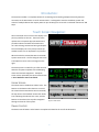
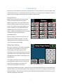
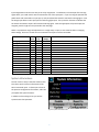
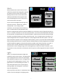
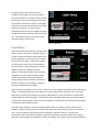
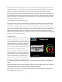
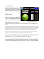
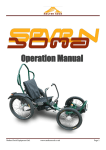
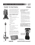
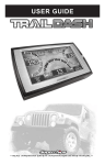
2015
User Manual
Bob Dixon
Research Service Bureau LLC
1/1/2015
Table of Contents
Introduction: ......................................................................................................................................................... 2
Touch Screen Navigation: ..................................................................................................................................... 2
Home Screen:.................................................................................................................................................... 2
Device Control: ................................................................................................................................................. 2
Feedback: .......................................................................................................................................................... 3
Other Buttons: .................................................................................................................................................. 3
Initial Setup: .......................................................................................................................................................... 4
Setup Screen: .................................................................................................................................................... 4
Relay/Input Setup: ............................................................................................................................................ 4
System Information: ......................................................................................................................................... 5
Using Auto Commander:....................................................................................................................................... 6
Winch: ............................................................................................................................................................... 7
Lights: ................................................................................................................................................................ 7
Dual Battery: ..................................................................................................................................................... 8
Onboard Air: ..................................................................................................................................................... 9
Horn: ............................................................................................................................................................... 11
Differential Locks: ........................................................................................................................................... 11
Hydrolock Sensor: ........................................................................................................................................... 12
1
Introduction:
The Auto Commander is a complete solution for connecting and controlling multiple electrically powered
accessories in the Automotive or similar environments. It is designed to ease the installation, power and
control of multiple devices that require power at up to 30 Amps per circuit with a combined maximum of 100
Amps.
Touch Screen Navigation:
Auto Commander uses a touch screen display as its
primary interface to the user. The touch screen
replaces over 15 separate physical switches and
provides indicator and status information that
can’t be had using conventional wiring techniques.
The touch display uses a very sturdy suction cup
window mount so it can be placed in any location.
When the vehicle is started the Auto Commander
system comes to life. The first thing the users sees
is the Splash screen as seen in the Figure on the
right.
The startup screen is visible for just a few seconds
Figure 1- Initial Startup Screen
while the computer completes its housekeeping
chores and activates equipment. The Splash
screen is then replaced by the Home screen shown
in Error! Reference source not found..
Home Screen:
The Home screen is divided into 3 basic areas. The
buttons on the bottom allow the user to control
the various devices attached to Auto Commander,
the top center is the Feedback section that shows
icons indicating what devices are active, and the
buttons on the sides at the top allow navigation
through and control of the system.
Figure 2- Home Screen
Device Control:
The device control buttons at the bottom are explained in detail in the rest of this document.
2
Feedback:
The Feedback area of the screen contains icons for the
various devices attached to Auto Commander. Each
icon indicates an active function. During the startup
process these icons are all flashed on for a few seconds
so that they are visible. When various lights and
systems are turned on the icons will appear and will
stay on as long as the device is turned on. The list of
icons are defined in Figure 3 and Figure 4
Function
Ignition On
Icon
Function
Winch
Fog Lights
Horn
Rear Lights
Compressor
Driving Lights
Battery
Running Lights
Front Locker
Flood Lights
Rear Locker
Rock Lights
Hydrolock
Icon
Figure 3- Icon Functions
Figure 4- Feedback Section of Home Screen
Other Buttons:
There are several buttons that are displayed throughout the interface that are defined below.
Description
Button
Description
Switch to Day Mode Screen
Go to the Home Screen
Switch to Night Mode Screen
Go to the Previous Screen
Switch to Blackout Screen
Go to the Next Screen
Change to Settings mode
Figure 5- Other Common Buttons
3
Button
Initial Setup:
When the unit is first installed, some setup is required before it is fully operational. Auto Commander needs
to be told what devices it is controlling and how those devices are connected. These configuration steps are
performed by selecting the tools/setup icon on the Main or Home screen.
Setup Screen:
When you press the tools button on the Home
screen you are presented with the “Enable
Options” setup screen. This screen allows you to
enable or disable the devices that the system can
control. If, for instance you have Fog Lights and
Lockers installed, you can enable those options.
Disabled options do not show up on the home
screen. Enable only those devices that are actually
installed and under control of the Auto
Commander system.
When the system is started for the first time, all
the options are disabled by default. Once the
Figure 6- Option Select Setup Screen
appropriate devices are enabled, press the right
arrow to proceed to the next page.
Relay/Input Setup:
This is the screen where you tell Auto Commander
what devices are attached to the relay ports.
These settings must reflect exactly what is
connected to each screw terminal port on the Auto
Commander device. Care must be taken to ensure
that appropriate fuse values are installed for each
powered device.
If, for instance you want to use relay 5 to operate
driving lights that require 25 Amps of power, you
must install a 30 Amp fuse in position 5 and
connect the driving lights to relay port 5.
Figure 7- Relay/Input Setup Screen
Instructions will appear on the screen. Each time you press the Assign Relay button the next possible device
name will appear. As in the example above, press “Assign Relay” until you are prompted for information for
the “Driving Lights”. Select the relay number from the keypad that the driving lights are connected to. This
new relay assignment will be saved.
4
Input assignments work the same way as the relay assignments. To elaborate on the example of the Driving
Lights above, you could install a switch connected to one of the input ports. If you are using the optional foot
pedal switch and connected it to input port 3, and you wanted that switch to activate the driving lights. Press
the Assign Input button until it prompts for the driving lights input. Then press the 3 button to indicate that
the switch connected to input 3 will activate the driving lights. Once the appropriate relays and inputs are
assigned, press the right arrow to proceed to the next page.
NOTE: it is possible to assign multiple devices to a single relay or input, so care must be taken in changing
these settings. Be sure to record what it connected to each port on Auto Commander.
Device
Relay
Port
Input
Port
Fuse Size
(Amps)
Note
Driving Lights
Fog Lights
Rock Lights
Rear Lights
Flood Lights
Running Lights
Air Compressor
Dual Battery Solenoid
Winch In
Winch Out
Front Locker
Rear Locker
Horn
System Information:
The last screen in setup is the Information screen.
This shows you the revision information of the
Auto Commander parts. It allows you to clear all
the previous configuration information, and it lets
you update the system firmware.
In addition to these things it lets you see the
systems internal temperature.
Figure 8- System Information Screen
5
Using Auto Commander:
The Auto Commander is an integrated controller that manages the operations of many automotive systems.
Typically these systems are independently managed using discrete switches with individual indicators. The
Auto Commander replaces all the discrete wiring, switches, and indicators with a computer controlled touch
screen display and relays.
The initial implementation of Auto Commander integrates the following systems and is illustrated by the next
figure which is the main screen of the controller.
Winch
Lights
Dual Battery
Onboard Air
Lockers
Horn
Hydrolock Sensor
Figure 9- Main Screen
Each system operates independently yet shares fundamental information about the vehicles operation and
systems. The following sections of this document define the operations of the devices that you may connect.
6
Winch:
Many individuals who install a winch on their
vehicle find a benefit from being able to operate
the system from the comfort of their vehicle.
Moving the winch control to the inside of the
vehicle provides better security against those
who would damage the winch or vehicle if the
winch controls were in the open.
As you can see in the Figure 10 to the right, the
winch has 3 controls. “Winch Arm”, Spool In,
and Spool Out. Arm is simply a safety
mechanism. You must press the Arm button to
Figure 10 Winch Control Screen
turn it on before either of the Spool button will
function. Arming the winch will also cause the feedback icon on the main screen to show that the winch is
active. It is similar in function to a cover over a physical switch. The cover must be lifted before the switch
can be activated. The Spool buttons are momentary buttons. When you press the switch with your finger
the winch is activated and when you release it the winch stops. This is a simple system in that there is no
special configurations that are required. However it is fully integrated with the other systems. Since the
Auto Commander computer can also manage an auxiliary battery, it will try to connect the secondary battery
before spooling. When the winch is armed, if both the onboard batteries are fully charged Auto Commander
will link the batteries together so that the winch will be provided as much electrical power as it needs. If,
while the winch is armed, both batteries drop below the minimum voltage, the battery link will be
disconnected to reserve enough energy in the remaining battery to restart the vehicle if necessary. Auto
Commander can only make these smart decisions if all the systems are fully integrated and under computer
control.
Lights:
There is an unlimited combination of lights that
individuals install on their vehicles. The light buttons
that are displayed on this screen are only the lights
that enabled in the Options screen. The Figure 11at
the right shows the lighting system controls. All 6
light switches are of the On/Off type of switch. In
that pressing the switch once, turns the light on,
pressing it again, turns the light off. Each switch
operates independently.
At the top of the screen there is a tools button that is
used to access the settings for the lighting system.
Figure 11 Lighting Control Screen
7
The light settings screen allows the user to
configure how the lights act when the vehicle is
started and shutdown. The button called “Startup
State” lets the user select if the lights will be in the
off state when the vehicle is started, of if the lights
should be in the same state they were in when the
vehicle was shutdown. The control called
“Shutdown Delay” lets the user configure how long
the lights will remain on after the vehicle is turned
off. The minimum setting is 0 seconds and the
maximum setting is 120 seconds.
Figure 12- Lights Settings
Dual Battery:
Auto Commander has the ability to manage a dual
battery system in the vehicle. Although this type
of setup is implemented much less frequently than
auxiliary lighting, it is an extremely critical system
for the serious off-roader. A dual battery system
can easily get a motorist out of a bind when the
electrical system is compromised and it provides
additional power for multiple accessories.
However a dual battery system must be properly
managed for it to be in optimal condition when
needed. Both batteries must be charged, the
auxiliary battery must be selectable, and when a
problem condition, like low voltage, is detected
Figure 13- Dual Battery Settings
the system should protect its integrity.
Figure 13 shows the Battery Control screen. It allows the user to configure the operation of the dual battery
system. The default settings are usually optimal, but can be adjusted for a specific use case. The system
operates by monitoring the voltage of each battery independently. Usually a dual battery system will be
installed where the normal operation of the vehicle as well as the engine and starter will operate using the
manufacturers installed battery. Where a secondary battery is installed, the accessories (Auto Commander)
is connected to this secondary battery.
The “High Target Voltage” is the desired voltage level that Auto Commander wants to maintain on the
batteries. When the vehicle starts, the alternator will charge the vehicles battery to achieve at least this
level. After the vehicle has started and one of the batteries reaches this level for 2 minutes, Auto
Commander will link both batteries together so that the second battery will be charged as well. During
operation, if both batteries drop below the “Isolate Low Voltage”, for 2 minutes, then the link between the
8
batteries will be disconnected. This protects one of the batteries with at least enough power to crank the
engine during a restart. The “Link” button allows the operator to manually force the linking of the second
batteries. This would be required if the primary battery was unable to start the vehicle, for instance.
The two digital indicators, Main(V) and Aux(V) show the current voltage of the batteries. When the Link is in
the disconnected state and the engine is off but the accessory switch is on, these show the true state of the
voltage on each battery. When the engine is running and the link is connected, both readouts will indicate
the voltage of the alternator output.
A brief explanation of the terms Main and Aux:
Auto Commander incorporates a power connection, 8 gauge RED wire in the power cable (see installation
wiring details). This large red cable is connected to the vehicles battery, all accessories connected to Auto
Commander pull power through this connection. Auto Commander assigns the name “Main” to this power
source. Auto Commander also has a connection to the second battery in the vehicle (if one is installed), 18
gauge RED wire in the power cable. This connection is used to sense the battery voltage of the second
battery and is assigned the name “Aux”. Depending on how the user connects these cables, determines what
particular battery is called Main and Aux.
Onboard Air:
Having an air compressor is a very handy thing in
the off-roading community. The ability to air down
one’s tires when on the trail improves traction and
improves the ride over rough terrain. When you
are finished on the trail just air back up and get
back on the road. Auto Commander fully controls
the operation of the onboard air system.
There are 2 parts that enable Auto Commander to
manage the air system. There is a pressure sensor,
called a transducer, and a relay that controls the
power to the compressor. The pressure sensor
reads the pressure of the air in the system and
Figure 14- Onboard Air Control
sends the data to the Auto Commander computer.
Auto Commander then turns the compressor on or off via the power relay to maintain the compressed air
source.
Figure 14 depicts the control screen for Onboard Air. There is an indicator showing the current air pressure
in Pounds/Square Inch (PSI) and a button to enable or disable the compressor.
At the top of the screen there is a tools button used to access the compressor settings. Pressing the tools
button changes to the setup screen.
9
Figure 15, as seen below, shows the basic settings
that can be configured for the compressor.
The “Start Delay” defines the number of seconds
after the engine is started that the system will wait
before the air compressor is turned on. This delay
allows the oil pressure to stabilize, and for the
alternator to turn on before the compressor load is
added to the engine. The minimum delay that can
be programmed is 15 seconds and the maximum is
300 seconds. It is a good idea, if you have a dual
battery system, to set this value to more than 120
seconds to allow the batteries to be linked before
Figure 15- Onboard Air Settings
the compressor is turned on.
The “Max PSI” value is the maximum pressure that your air compressor can generate. Many electric air
compressors are rated for 150 PSI, some are rated for as much as 200 PSI. The value entered here is the level
that the compressor will try to achieve before turning off.
NOTE 1: Every Onboard Air system should have a pressure relief valve to operate safely. The pressure relief
valve must have a rating that corresponds with the compressor maximum pressure. So if you have a 150 PSI
compressor, your relief valve should be rated at a value less than 150 PSI. Also the “Maximum PSI” value
entered into Auto Commander must be less than the relief valve rating. Typically a 150 PSI compressor
would be paired with a 140 PSI relief valve and Auto Commander “Max PSI” would be set to 130 PSI.
NOTE 2: Most air compressors are not rated for continuous operation at their maximum pressure. If a
compressor has a maximum continuous pressure of 100 PSI, then Auto Commanders “Max PSI” value should
be set to 100 PSI. This will prevent the compressor from being over worked and exceeding its design
specification. If the compressor is not rated at 100% duty cycle, then the user must manually enable/disable
the compressor so that the duty cycle design specification is not exceeded during periods of high demand for
air.
The “Minimum PSI” setting tells Auto Commander how low the pressure can get before it turns the
compressor on. Auto commander will turn the compressor on when the pressure gets too low and will turn it
off when the pressure in the system is high enough.
The final setting for the Onboard Air system is the “Startup State”. This can be either On or Off. If set to On,
the compressor will be enabled when the vehicle is started, if it is set to Off, the compressor will be Off. This
setting equates to Automatic compressor control or Manual. In an environment where the OBA system is
used infrequently, a Startup State of Off may be the best setting. Where compressed air is used often, the
preferred setting may be set to “On”.
10
Horn:
The horn is controlled by a single button on the
main screen. There are no settings associated with
the horn other than simply pressing the horn
button.
The horn button is a momentary type of switch.
Pressing the switch turns the horn relay on, and
releasing it turn the relay off.
The type of horn, Electric or Air, can be whatever
the users selects. By selection of the proper fuse,
the horn circuit can activate an electric horn
directly, or it can activate and air solenoid for an
air horn.
Figure 16- Horn Button on Main Screen
Differential Locks:
Auto Commander has a screen dedicated to the
function of Locking Differentials. Pressing the
Lockers button on the main screen allows the
independent control of the front and rear locking
function. To lock or unlock the front and/or rear
differential, simply press the differential (round
part of the axle).
When the differentials are locked, a small yellow
lock is displayed in the screen.
Note: Operation of the locking differentials is not
Figure 17- Locking Differentials (unlocked)
recommended at high speeds. Safe driving
practices must be used with the locking
differentials.
Figure 18- Locking Differentials (locked)
11
Hydrolock Sensor:
The Auto Commander Hydrolock sensor system
was developed for the off road enthusiast that
often drives through deep water. It is a warning
system only and cannot prevent engine damage
if water enters the engine. It can only provide a
warning that the level of water is too high where
the sensor is mounted.
Although installing a snorkel is an option that
almost converts your vehicle into a submarine, a
snorkel can be expensive and it usually requires
modifications to the body and other painted
surfaces. For this reason we developed a sensor
Figure 19 Hydrolock Warning Screen
to tell you when the water level in the engine
compartment is getting high. The Hydrolock sensor helps the driver avoid water deep enough to require a
snorkel.
The Hydrolock sensor provides a user with an early warning of dangerous water levels. The sensor is a tube
that is approximately 1 foot in length. It is mounted vertically in the engine compartment with the top of the
sensor at the same level as the air intake vent. In this configuration the depth of the water is continuously
monitored and if the level gets too high in the engine compartment, a warning is issued on the Auto
Commander main screen and on the Hydrolock screen. The water is detected at the bottom level of the
sensor and as the water level increases the sensor will indicate the amount of increase.
The Hydrolock Warning screen, Figure 19, contains a large indicator light that shows the current alarm status.
A green check indicates that the water level is below the alarm level, a red ex indicates that the alarm level
has been exceeded. There is a bar graph indicator that shows the current water level.
There are two other controls on this screen that allow the user to configure the system to their desire. The
“Alarm Level” slider lets the user select the level at which an alarm is issued. There are 4 graduations on the
slider that correspond to the water level marks on the gauge tube. There is also a “Warning Enable/Disable”
button. When disabled the system will ignore all water levels.
12