1
Freescale Semiconductor, Inc.
MCUEZASM08/D
Freescale Semiconductor, Inc...
February 1998
MCUez
ASSEMBLER
USER’S MANUAL
Copyright 1998 MOTOROLA and HIWARE AG; All Rights Reserved
For More Information On This Product,
Go to: www.freescale.com
Freescale Semiconductor, Inc.
Freescale Semiconductor, Inc...
Important Notice to Users
While every effort has been made to ensure the accuracy of all information in this document,
Motorola assumes no liability to any party for any loss or damage caused by errors or omissions or
by statements of any kind in this document, its updates, supplements, or special editions, whether
such errors are omissions or statements resulting from negligence, accident, or any other cause.
Motorola further assumes no liability arising out of the application or use of any information,
product, or system described herein; nor any liability for incidental or consequential damages
arising from the use of this document. Motorola disclaims all warranties regarding the
information contained herein, whether expressed, implied, or statutory, including implied
warranties of merchantability or fitness for a particular purpose. Motorola makes no
representation that the interconnection of products in the manner described herein will not
infringe on existing or future patent rights, nor do the descriptions contained herein imply the
granting or license to make, use or sell equipment constructed in accordance with this description.
Information contained in this document applies to
REVision (0) MCUez.
The computer program contains material copyrighted by Motorola Inc., first published 1997, and may
be used only under a license such as the License For Computer Programs (Article 14) contained in
Motorola's Terms and Conditions of Sale, Rev. 1/79.
Trademarks
This document includes these trademarks:
MCUez is a trademark of Motorola Inc.
EXORciser is a trademark of Motorola Inc.
The MCUez development, emulation, and debugging application is based on HI-WAVE; a
software technology developed by the HIWARE. HI-WAVE is a registered trademark of
HIWARE AG.
AIX, IBM, and PowerPC are trademarks of International Business Machines Corporation.
SPARC is a trademark of SPARC international, Inc.
Sun and SunOS are trademarks of Sun Microsystems, Inc.
UNIX is a trademark of Novell, Inc., in the United States and other countries, licensed exclusively
through X/Open Company, Ltd.
X Window System is a trademark of Massachusetts Institute of Technology.
Motorola and the Motorola logo are registered trademarks of Motorola Inc.
For More Information On This Product,
Go to: www.freescale.com
Freescale Semiconductor, Inc.
CONTENTS
CONTENTS
Freescale Semiconductor, Inc...
CHAPTER 1 GENERAL INFORMATION
1.1 INTRODUCTION . . . . . . . . . . . . . . . . . . . . . . . . . . . . . . . . . . . . . . . . . . . . . . . . . . . . . . . . . . .
1.2 STRUCTURE OF THIS MANUAL . . . . . . . . . . . . . . . . . . . . . . . . . . . . . . . . . . . . . . . . . . . . .
1.3 GETTING STARTED . . . . . . . . . . . . . . . . . . . . . . . . . . . . . . . . . . . . . . . . . . . . . . . . . . . . . . . .
1.3.1 Write An Assembly Source File. . . . . . . . . . . . . . . . . . . . . . . . . . . . . . . . . . . . . . . . . . . . .
1.3.2 Assemble A Source File. . . . . . . . . . . . . . . . . . . . . . . . . . . . . . . . . . . . . . . . . . . . . . . . . . .
1.3.3 Link An Application . . . . . . . . . . . . . . . . . . . . . . . . . . . . . . . . . . . . . . . . . . . . . . . . . . . . .
1-1
1-1
1-2
1-2
1-3
1-6
CHAPTER 2 GRAPHICAL USER INTERFACE
2.1 INTRODUCTION . . . . . . . . . . . . . . . . . . . . . . . . . . . . . . . . . . . . . . . . . . . . . . . . . . . . . . . . . . .
2.2 STARTING THE MOTOROLA ASSEMBLER. . . . . . . . . . . . . . . . . . . . . . . . . . . . . . . . . . . .
2.3 ASSEMBLER GRAPHICAL INTERFACE . . . . . . . . . . . . . . . . . . . . . . . . . . . . . . . . . . . . . . .
2.3.1 Window Title . . . . . . . . . . . . . . . . . . . . . . . . . . . . . . . . . . . . . . . . . . . . . . . . . . . . . . . . . . .
2.3.2 Content Area . . . . . . . . . . . . . . . . . . . . . . . . . . . . . . . . . . . . . . . . . . . . . . . . . . . . . . . . . . .
2.3.3 Assembler Toolbar . . . . . . . . . . . . . . . . . . . . . . . . . . . . . . . . . . . . . . . . . . . . . . . . . . . . . . .
2.3.4 Status Bar . . . . . . . . . . . . . . . . . . . . . . . . . . . . . . . . . . . . . . . . . . . . . . . . . . . . . . . . . . . . . .
2.3.5 Assembler Menu Bar . . . . . . . . . . . . . . . . . . . . . . . . . . . . . . . . . . . . . . . . . . . . . . . . . . . . .
2-1
2-1
2-2
2-2
2-3
2-4
2-4
2-5
2.3.5.1 File Menu. . . . . . . . . . . . . . . . . . . . . . . . . . . . . . . . . . . . . . . . . . . . . . . . . . . . . . . . . . . . . . . . . .2-5
2.3.5.1.1 Editor Settings Dialog . . . . . . . . . . . . . . . . . . . . . . . . . . . . . . . . . . . . . . . . . . . . 2-6
2.3.5.1.2 Important Remarks . . . . . . . . . . . . . . . . . . . . . . . . . . . . . . . . . . . . . . . . . . . . . . 2-10
2.3.5.1.3 Configuration Dialog . . . . . . . . . . . . . . . . . . . . . . . . . . . . . . . . . . . . . . . . . . . . 2-10
2.3.5.2 Assembler Menu . . . . . . . . . . . . . . . . . . . . . . . . . . . . . . . . . . . . . . . . . . . . . . . . . . . . . . . . . . .2-12
2.3.5.3 View Menu. . . . . . . . . . . . . . . . . . . . . . . . . . . . . . . . . . . . . . . . . . . . . . . . . . . . . . . . . . . . . . . .2-12
2.3.6 Advanced Options Settings Dialog Box . . . . . . . . . . . . . . . . . . . . . . . . . . . . . . . . . . . . . 2-12
2.3.7 Specifying The Input File . . . . . . . . . . . . . . . . . . . . . . . . . . . . . . . . . . . . . . . . . . . . . . . . 2-13
2.3.7.1 Editable Combo Box . . . . . . . . . . . . . . . . . . . . . . . . . . . . . . . . . . . . . . . . . . . . . . . . . . . . . . . .2-13
2.3.7.2 File/Assemble . . . . . . . . . . . . . . . . . . . . . . . . . . . . . . . . . . . . . . . . . . . . . . . . . . . . . . . . . . . . .2-13
2.3.7.3 Drag And Drop . . . . . . . . . . . . . . . . . . . . . . . . . . . . . . . . . . . . . . . . . . . . . . . . . . . . . . . . . . . .2-14
2.3.8 Error Feedback . . . . . . . . . . . . . . . . . . . . . . . . . . . . . . . . . . . . . . . . . . . . . . . . . . . . . . . . . 2-14
2.3.8.1 Error Feedback Using Information From The Assembler Window . . . . . . . . . . . . . . . . . . . .2-14
2.3.8.2 Error Feedback From A User-Defined Editor . . . . . . . . . . . . . . . . . . . . . . . . . . . . . . . . . . . . .2-14
2.3.8.2.1 Editors That Can Start With A Line Number On The Command Line . . . . . . 2-14
2.3.8.2.2 Editors That Cannot Start With A Line Number On The Command Line. . . . 2-15
MCUEZASM08/D
For More Information On This Product,
Go to: www.freescale.com
iii
Freescale Semiconductor, Inc.
CONTENTS
Freescale Semiconductor, Inc...
CHAPTER 3 ENVIRONMENT
3.1 INTRODUCTION . . . . . . . . . . . . . . . . . . . . . . . . . . . . . . . . . . . . . . . . . . . . . . . . . . . . . . . . . . .
3.2 PATHS. . . . . . . . . . . . . . . . . . . . . . . . . . . . . . . . . . . . . . . . . . . . . . . . . . . . . . . . . . . . . . . . . . . .
3.3 LINE CONTINUATION . . . . . . . . . . . . . . . . . . . . . . . . . . . . . . . . . . . . . . . . . . . . . . . . . . . . . .
3.4 ENVIRONMENT VARIABLES DESCRIPTIONS . . . . . . . . . . . . . . . . . . . . . . . . . . . . . . . . .
3.4.1 ASMOPTIONS . . . . . . . . . . . . . . . . . . . . . . . . . . . . . . . . . . . . . . . . . . . . . . . . . . . . . . . . .
3.4.2 GENPATH . . . . . . . . . . . . . . . . . . . . . . . . . . . . . . . . . . . . . . . . . . . . . . . . . . . . . . . . . . . . .
3.4.3 ABSPATH . . . . . . . . . . . . . . . . . . . . . . . . . . . . . . . . . . . . . . . . . . . . . . . . . . . . . . . . . . . . .
3.4.4 OBJPATH . . . . . . . . . . . . . . . . . . . . . . . . . . . . . . . . . . . . . . . . . . . . . . . . . . . . . . . . . . . . . .
3.4.5 TEXTPATH . . . . . . . . . . . . . . . . . . . . . . . . . . . . . . . . . . . . . . . . . . . . . . . . . . . . . . . . . . . .
3.4.6 SRECORD . . . . . . . . . . . . . . . . . . . . . . . . . . . . . . . . . . . . . . . . . . . . . . . . . . . . . . . . . . . . .
3.4.7 ERRORFILE . . . . . . . . . . . . . . . . . . . . . . . . . . . . . . . . . . . . . . . . . . . . . . . . . . . . . . . . . . .
3.4.8 INCLUDETIME: Creation Time In Object File . . . . . . . . . . . . . . . . . . . . . . . . . . . . . . . .
3.4.9 USERNAME: User Name In Object File . . . . . . . . . . . . . . . . . . . . . . . . . . . . . . . . . . . . .
3-1
3-2
3-2
3-3
3-4
3-4
3-5
3-5
3-5
3-6
3-7
3-9
3-9
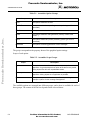
CHAPTER 4 FILES
4.1 INTRODUCTION . . . . . . . . . . . . . . . . . . . . . . . . . . . . . . . . . . . . . . . . . . . . . . . . . . . . . . . . . . .
4.2 INPUT FILES . . . . . . . . . . . . . . . . . . . . . . . . . . . . . . . . . . . . . . . . . . . . . . . . . . . . . . . . . . . . . .
4.2.1 Source Files . . . . . . . . . . . . . . . . . . . . . . . . . . . . . . . . . . . . . . . . . . . . . . . . . . . . . . . . . . . .
4.2.2 Include File . . . . . . . . . . . . . . . . . . . . . . . . . . . . . . . . . . . . . . . . . . . . . . . . . . . . . . . . . . . .
4.3 OUTPUT FILES . . . . . . . . . . . . . . . . . . . . . . . . . . . . . . . . . . . . . . . . . . . . . . . . . . . . . . . . . . . .
4.3.1 Object Files . . . . . . . . . . . . . . . . . . . . . . . . . . . . . . . . . . . . . . . . . . . . . . . . . . . . . . . . . . . .
4.3.2 Absolute Files . . . . . . . . . . . . . . . . . . . . . . . . . . . . . . . . . . . . . . . . . . . . . . . . . . . . . . . . . .
4.3.3 Motorola S Files. . . . . . . . . . . . . . . . . . . . . . . . . . . . . . . . . . . . . . . . . . . . . . . . . . . . . . . . .
4.3.4 Listing Files . . . . . . . . . . . . . . . . . . . . . . . . . . . . . . . . . . . . . . . . . . . . . . . . . . . . . . . . . . . .
4.3.5 Debug Listing Files . . . . . . . . . . . . . . . . . . . . . . . . . . . . . . . . . . . . . . . . . . . . . . . . . . . . . .
4.3.6 Error Listing File . . . . . . . . . . . . . . . . . . . . . . . . . . . . . . . . . . . . . . . . . . . . . . . . . . . . . . . .
4-1
4-1
4-1
4-1
4-1
4-2
4-2
4-2
4-2
4-3
4-3
CHAPTER 5 ASSEMBLER OPTIONS
5.1 INTRODUCTION . . . . . . . . . . . . . . . . . . . . . . . . . . . . . . . . . . . . . . . . . . . . . . . . . . . . . . . . . . . 5-1
5.2 ASMOPTIONS . . . . . . . . . . . . . . . . . . . . . . . . . . . . . . . . . . . . . . . . . . . . . . . . . . . . . . . . . . . . . 5-1
5.3 ASSEMBLER OPTION DESCRIPTIONS . . . . . . . . . . . . . . . . . . . . . . . . . . . . . . . . . . . . . . . . 5-3
5.3.1 -Ci. . . . . . . . . . . . . . . . . . . . . . . . . . . . . . . . . . . . . . . . . . . . . . . . . . . . . . . . . . . . . . . . . . . . 5-4
5.3.2 -Env . . . . . . . . . . . . . . . . . . . . . . . . . . . . . . . . . . . . . . . . . . . . . . . . . . . . . . . . . . . . . . . . . . 5-4
5.3.3 -F2/-FA2 . . . . . . . . . . . . . . . . . . . . . . . . . . . . . . . . . . . . . . . . . . . . . . . . . . . . . . . . . . . . . . . 5-5
5.3.4 -H . . . . . . . . . . . . . . . . . . . . . . . . . . . . . . . . . . . . . . . . . . . . . . . . . . . . . . . . . . . . . . . . . . . . 5-6
5.3.5 -L . . . . . . . . . . . . . . . . . . . . . . . . . . . . . . . . . . . . . . . . . . . . . . . . . . . . . . . . . . . . . . . . . . . . 5-7
5.3.6 -Lc . . . . . . . . . . . . . . . . . . . . . . . . . . . . . . . . . . . . . . . . . . . . . . . . . . . . . . . . . . . . . . . . . . . 5-9
5.3.7 -Ld . . . . . . . . . . . . . . . . . . . . . . . . . . . . . . . . . . . . . . . . . . . . . . . . . . . . . . . . . . . . . . . . . . 5-10
5.3.8 -Le . . . . . . . . . . . . . . . . . . . . . . . . . . . . . . . . . . . . . . . . . . . . . . . . . . . . . . . . . . . . . . . . . . 5-11
5.3.9 -Li. . . . . . . . . . . . . . . . . . . . . . . . . . . . . . . . . . . . . . . . . . . . . . . . . . . . . . . . . . . . . . . . . . . 5-12
iv
For More Information On This Product,
Go to: www.freescale.com
MCUEZASM08/D
Freescale Semiconductor, Inc.
CONTENTS
Freescale Semiconductor, Inc...
5.3.10
5.3.11
5.3.12
5.3.13
5.3.14
5.3.15
5.3.16
5.3.17
5.3.18
5.3.19
-Ms/-Mb . . . . . . . . . . . . . . . . . . . . . . . . . . . . . . . . . . . . . . . . . . . . . . . . . . . . . . . . . . . . .
-N . . . . . . . . . . . . . . . . . . . . . . . . . . . . . . . . . . . . . . . . . . . . . . . . . . . . . . . . . . . . . . . . . .
-V . . . . . . . . . . . . . . . . . . . . . . . . . . . . . . . . . . . . . . . . . . . . . . . . . . . . . . . . . . . . . . . . . .
-W1. . . . . . . . . . . . . . . . . . . . . . . . . . . . . . . . . . . . . . . . . . . . . . . . . . . . . . . . . . . . . . . . .
-W2. . . . . . . . . . . . . . . . . . . . . . . . . . . . . . . . . . . . . . . . . . . . . . . . . . . . . . . . . . . . . . . . .
-WmsgNe . . . . . . . . . . . . . . . . . . . . . . . . . . . . . . . . . . . . . . . . . . . . . . . . . . . . . . . . . . . .
-WmsgNi . . . . . . . . . . . . . . . . . . . . . . . . . . . . . . . . . . . . . . . . . . . . . . . . . . . . . . . . . . . .
-WmsgNw . . . . . . . . . . . . . . . . . . . . . . . . . . . . . . . . . . . . . . . . . . . . . . . . . . . . . . . . . . .
-WmsgFbv/ -WmsgFbm . . . . . . . . . . . . . . . . . . . . . . . . . . . . . . . . . . . . . . . . . . . . . . . .
-WmsgFiv/-WmsgFim . . . . . . . . . . . . . . . . . . . . . . . . . . . . . . . . . . . . . . . . . . . . . . . . . .
5-13
5-14
5-15
5-16
5-17
5-18
5-19
5-20
5-21
5-22
CHAPTER 6 SECTIONS
6.1 INTRODUCTION . . . . . . . . . . . . . . . . . . . . . . . . . . . . . . . . . . . . . . . . . . . . . . . . . . . . . . . . . . .
6.2 SECTION ATTRIBUTE . . . . . . . . . . . . . . . . . . . . . . . . . . . . . . . . . . . . . . . . . . . . . . . . . . . . . .
6.2.1 Data Sections . . . . . . . . . . . . . . . . . . . . . . . . . . . . . . . . . . . . . . . . . . . . . . . . . . . . . . . . . . .
6.2.2 Constant Data Sections . . . . . . . . . . . . . . . . . . . . . . . . . . . . . . . . . . . . . . . . . . . . . . . . . . .
6.2.3 Code Sections. . . . . . . . . . . . . . . . . . . . . . . . . . . . . . . . . . . . . . . . . . . . . . . . . . . . . . . . . . .
6.3 SECTION TYPE . . . . . . . . . . . . . . . . . . . . . . . . . . . . . . . . . . . . . . . . . . . . . . . . . . . . . . . . . . . .
6.3.1 Absolute Sections. . . . . . . . . . . . . . . . . . . . . . . . . . . . . . . . . . . . . . . . . . . . . . . . . . . . . . . .
6.3.2 Relocatable Sections . . . . . . . . . . . . . . . . . . . . . . . . . . . . . . . . . . . . . . . . . . . . . . . . . . . . .
6.3.3 Relocatable Versus Absolute Section. . . . . . . . . . . . . . . . . . . . . . . . . . . . . . . . . . . . . . . . .
6.3.3.1
6.3.3.2
6.3.3.3
6.3.3.4
6-1
6-1
6-1
6-1
6-2
6-2
6-2
6-4
6-6
Early Development . . . . . . . . . . . . . . . . . . . . . . . . . . . . . . . . . . . . . . . . . . . . . . . . . . . . . . . . . .6-6
Enhanced Portability . . . . . . . . . . . . . . . . . . . . . . . . . . . . . . . . . . . . . . . . . . . . . . . . . . . . . . . . .6-7
Tracking Overlaps . . . . . . . . . . . . . . . . . . . . . . . . . . . . . . . . . . . . . . . . . . . . . . . . . . . . . . . . . . .6-7
Reusability . . . . . . . . . . . . . . . . . . . . . . . . . . . . . . . . . . . . . . . . . . . . . . . . . . . . . . . . . . . . . . . . .6-7
CHAPTER 7 ASSEMBLER SYNTAX
7.1 INTRODUCTION . . . . . . . . . . . . . . . . . . . . . . . . . . . . . . . . . . . . . . . . . . . . . . . . . . . . . . . . . . .
7.1.1 Comment Line . . . . . . . . . . . . . . . . . . . . . . . . . . . . . . . . . . . . . . . . . . . . . . . . . . . . . . . . . .
7.1.2 Source Line . . . . . . . . . . . . . . . . . . . . . . . . . . . . . . . . . . . . . . . . . . . . . . . . . . . . . . . . . . . .
7.1.3 Label Field . . . . . . . . . . . . . . . . . . . . . . . . . . . . . . . . . . . . . . . . . . . . . . . . . . . . . . . . . . . . .
7.1.4 Operation Field . . . . . . . . . . . . . . . . . . . . . . . . . . . . . . . . . . . . . . . . . . . . . . . . . . . . . . . . .
7-1
7-1
7-1
7-1
7-2
7.1.4.1 Instruction . . . . . . . . . . . . . . . . . . . . . . . . . . . . . . . . . . . . . . . . . . . . . . . . . . . . . . . . . . . . . . . . .7-2
7.1.4.2 Directive . . . . . . . . . . . . . . . . . . . . . . . . . . . . . . . . . . . . . . . . . . . . . . . . . . . . . . . . . . . . . . . . . .7-2
7.1.4.3 Macro Name . . . . . . . . . . . . . . . . . . . . . . . . . . . . . . . . . . . . . . . . . . . . . . . . . . . . . . . . . . . . . . .7-2
7.1.5 Operand Field. . . . . . . . . . . . . . . . . . . . . . . . . . . . . . . . . . . . . . . . . . . . . . . . . . . . . . . . . . . 7-3
7.1.5.1
7.1.5.2
7.1.5.3
7.1.5.4
7.1.5.5
7.1.5.6
Inherent . . . . . . . . . . . . . . . . . . . . . . . . . . . . . . . . . . . . . . . . . . . . . . . . . . . . . . . . . . . . . . . . . . .7-3
Immediate . . . . . . . . . . . . . . . . . . . . . . . . . . . . . . . . . . . . . . . . . . . . . . . . . . . . . . . . . . . . . . . . .7-4
Direct . . . . . . . . . . . . . . . . . . . . . . . . . . . . . . . . . . . . . . . . . . . . . . . . . . . . . . . . . . . . . . . . . . . . .7-5
Extended . . . . . . . . . . . . . . . . . . . . . . . . . . . . . . . . . . . . . . . . . . . . . . . . . . . . . . . . . . . . . . . . . .7-6
Indexed, No Offset. . . . . . . . . . . . . . . . . . . . . . . . . . . . . . . . . . . . . . . . . . . . . . . . . . . . . . . . . . .7-6
Indexed, 8-Bit Offset . . . . . . . . . . . . . . . . . . . . . . . . . . . . . . . . . . . . . . . . . . . . . . . . . . . . . . . . .7-7
MCUEZASM08/D
For More Information On This Product,
Go to: www.freescale.com
v
Freescale Semiconductor, Inc.
CONTENTS
Freescale Semiconductor, Inc...
7.1.5.7 Indexed, 16-Bit Offset . . . . . . . . . . . . . . . . . . . . . . . . . . . . . . . . . . . . . . . . . . . . . . . . . . . . . . . .7-8
7.1.5.8 Relative . . . . . . . . . . . . . . . . . . . . . . . . . . . . . . . . . . . . . . . . . . . . . . . . . . . . . . . . . . . . . . . . . . .7-8
7.1.5.9 Stack Pointer, 8-Bit Offset . . . . . . . . . . . . . . . . . . . . . . . . . . . . . . . . . . . . . . . . . . . . . . . . . . . . .7-9
7.1.5.10 Stack Pointer, 16-Bit Offset. . . . . . . . . . . . . . . . . . . . . . . . . . . . . . . . . . . . . . . . . . . . . . . . . . .7-9
7.1.5.11 Memory To Memory Immediate To Direct . . . . . . . . . . . . . . . . . . . . . . . . . . . . . . . . . . . . . .7-10
7.1.5.12 Memory To Memory Direct To Direct . . . . . . . . . . . . . . . . . . . . . . . . . . . . . . . . . . . . . . . . .7-10
7.1.5.13 Memory To Memory Indexed To Direct With Post Increment . . . . . . . . . . . . . . . . . . . . . . . 7-11
7.1.5.14 Memory To Memory Direct To Indexed With Post Increment . . . . . . . . . . . . . . . . . . . . . . .7-12
7.1.5.15 Indexed With Post Increment. . . . . . . . . . . . . . . . . . . . . . . . . . . . . . . . . . . . . . . . . . . . . . . . .7-13
7.1.5.16 Indexed, 8-bit offset With Post Increment . . . . . . . . . . . . . . . . . . . . . . . . . . . . . . . . . . . . . . .7-14
7.1.5.17 Comment Field . . . . . . . . . . . . . . . . . . . . . . . . . . . . . . . . . . . . . . . . . . . . . . . . . . . . . . . . . . .7-14
7.2 SYMBOLS. . . . . . . . . . . . . . . . . . . . . . . . . . . . . . . . . . . . . . . . . . . . . . . . . . . . . . . . . . . . . . . .
7.2.1 User Defined Symbols . . . . . . . . . . . . . . . . . . . . . . . . . . . . . . . . . . . . . . . . . . . . . . . . . . .
7.2.2 External Symbols . . . . . . . . . . . . . . . . . . . . . . . . . . . . . . . . . . . . . . . . . . . . . . . . . . . . . . .
7.2.3 Undefined Symbols . . . . . . . . . . . . . . . . . . . . . . . . . . . . . . . . . . . . . . . . . . . . . . . . . . . . .
7.2.4 Reserved Symbols . . . . . . . . . . . . . . . . . . . . . . . . . . . . . . . . . . . . . . . . . . . . . . . . . . . . . .
7.3 CONSTANTS . . . . . . . . . . . . . . . . . . . . . . . . . . . . . . . . . . . . . . . . . . . . . . . . . . . . . . . . . . . . .
7.3.1 Integer Constants . . . . . . . . . . . . . . . . . . . . . . . . . . . . . . . . . . . . . . . . . . . . . . . . . . . . . . .
7.3.2 String Constants . . . . . . . . . . . . . . . . . . . . . . . . . . . . . . . . . . . . . . . . . . . . . . . . . . . . . . . .
7.3.3 Floating-Point Constants . . . . . . . . . . . . . . . . . . . . . . . . . . . . . . . . . . . . . . . . . . . . . . . . .
7.4 OPERATORS . . . . . . . . . . . . . . . . . . . . . . . . . . . . . . . . . . . . . . . . . . . . . . . . . . . . . . . . . . . . .
7.4.1 Addition And Subtraction Operators (Binary). . . . . . . . . . . . . . . . . . . . . . . . . . . . . . . . .
7.4.2 Multiplication, Division And Modulo Operators (Binary) . . . . . . . . . . . . . . . . . . . . . . .
7.4.3 Sign Operators (Unary) . . . . . . . . . . . . . . . . . . . . . . . . . . . . . . . . . . . . . . . . . . . . . . . . . .
7.4.4 Shift Operators (Binary). . . . . . . . . . . . . . . . . . . . . . . . . . . . . . . . . . . . . . . . . . . . . . . . . .
7.4.5 Bitwise Operators (Binary) . . . . . . . . . . . . . . . . . . . . . . . . . . . . . . . . . . . . . . . . . . . . . . .
7.4.6 Bitwise Operators (Unary) . . . . . . . . . . . . . . . . . . . . . . . . . . . . . . . . . . . . . . . . . . . . . . . .
7.4.7 Logical Operators (Unary) . . . . . . . . . . . . . . . . . . . . . . . . . . . . . . . . . . . . . . . . . . . . . . . .
7.4.8 Relational Operators (Binary) . . . . . . . . . . . . . . . . . . . . . . . . . . . . . . . . . . . . . . . . . . . . .
7.4.9 HIGH Operator . . . . . . . . . . . . . . . . . . . . . . . . . . . . . . . . . . . . . . . . . . . . . . . . . . . . . . . .
7.4.10 LOW Operator . . . . . . . . . . . . . . . . . . . . . . . . . . . . . . . . . . . . . . . . . . . . . . . . . . . . . . . .
7.4.11 Memory PAGE Operator (Unary) . . . . . . . . . . . . . . . . . . . . . . . . . . . . . . . . . . . . . . . . .
7.4.12 Force Operator (Unary) . . . . . . . . . . . . . . . . . . . . . . . . . . . . . . . . . . . . . . . . . . . . . . . . .
7.5 EXPRESSION . . . . . . . . . . . . . . . . . . . . . . . . . . . . . . . . . . . . . . . . . . . . . . . . . . . . . . . . . . . . .
7.5.1 Absolute Expression . . . . . . . . . . . . . . . . . . . . . . . . . . . . . . . . . . . . . . . . . . . . . . . . . . . .
7.5.2 Simple Relocatable Expression . . . . . . . . . . . . . . . . . . . . . . . . . . . . . . . . . . . . . . . . . . . .
7.6 TRANSLATION LIMITS . . . . . . . . . . . . . . . . . . . . . . . . . . . . . . . . . . . . . . . . . . . . . . . . . . . .
vi
For More Information On This Product,
Go to: www.freescale.com
7-15
7-15
7-15
7-16
7-16
7-16
7-16
7-17
7-17
7-17
7-17
7-17
7-18
7-18
7-18
7-19
7-19
7-20
7-20
7-21
7-21
7-22
7-24
7-24
7-25
7-27
MCUEZASM08/D
Freescale Semiconductor, Inc.
CONTENTS
Freescale Semiconductor, Inc...
CHAPTER 8 ASSEMBLER DIRECTIVES
8.1 INTRODUCTION . . . . . . . . . . . . . . . . . . . . . . . . . . . . . . . . . . . . . . . . . . . . . . . . . . . . . . . . . . . 8-1
8.2 DIRECTIVE OVERVIEW . . . . . . . . . . . . . . . . . . . . . . . . . . . . . . . . . . . . . . . . . . . . . . . . . . . . 8-1
8.2.1 Section Definition Directives. . . . . . . . . . . . . . . . . . . . . . . . . . . . . . . . . . . . . . . . . . . . . . . 8-1
8.2.2 Constant Definition Directives. . . . . . . . . . . . . . . . . . . . . . . . . . . . . . . . . . . . . . . . . . . . . . 8-1
8.2.3 Data Allocation Directives. . . . . . . . . . . . . . . . . . . . . . . . . . . . . . . . . . . . . . . . . . . . . . . . . 8-2
8.2.4 Symbol Linkage Directives . . . . . . . . . . . . . . . . . . . . . . . . . . . . . . . . . . . . . . . . . . . . . . . . 8-2
8.2.5 Assembly Control Directives . . . . . . . . . . . . . . . . . . . . . . . . . . . . . . . . . . . . . . . . . . . . . . . 8-2
8.2.6 Listing File Control Directives . . . . . . . . . . . . . . . . . . . . . . . . . . . . . . . . . . . . . . . . . . . . . 8-3
8.2.7 Macro Control Directives. . . . . . . . . . . . . . . . . . . . . . . . . . . . . . . . . . . . . . . . . . . . . . . . . . 8-3
8.2.8 Conditional Assembly Directives . . . . . . . . . . . . . . . . . . . . . . . . . . . . . . . . . . . . . . . . . . . 8-4
8.3 ABSENTRY - APPLICATION ENTRY POINT . . . . . . . . . . . . . . . . . . . . . . . . . . . . . . . . . . . 8-5
8.4 ALIGN - ALIGN LOCATION COUNTER . . . . . . . . . . . . . . . . . . . . . . . . . . . . . . . . . . . . . . . 8-6
8.5 BASE - SET NUMBER BASE . . . . . . . . . . . . . . . . . . . . . . . . . . . . . . . . . . . . . . . . . . . . . . . . . 8-7
8.6 CLIST - LIST CONDITIONAL ASSEMBLY . . . . . . . . . . . . . . . . . . . . . . . . . . . . . . . . . . . . . 8-8
8.7 DC - DEFINE CONSTANT . . . . . . . . . . . . . . . . . . . . . . . . . . . . . . . . . . . . . . . . . . . . . . . . . . 8-10
8.8 DCB - DEFINE CONSTANT BLOCK. . . . . . . . . . . . . . . . . . . . . . . . . . . . . . . . . . . . . . . . . . 8-12
8.9 DS - DEFINE SPACE . . . . . . . . . . . . . . . . . . . . . . . . . . . . . . . . . . . . . . . . . . . . . . . . . . . . . . . 8-13
8.10 ELSE - CONDITIONAL ASSEMBLY. . . . . . . . . . . . . . . . . . . . . . . . . . . . . . . . . . . . . . . . . 8-14
8.11 END - END ASSEMBLY . . . . . . . . . . . . . . . . . . . . . . . . . . . . . . . . . . . . . . . . . . . . . . . . . . . 8-15
8.12 ENDIF - END CONDITIONAL ASSEMBLY . . . . . . . . . . . . . . . . . . . . . . . . . . . . . . . . . . . 8-16
8.13 ENDM - END MACRO DEFINITION. . . . . . . . . . . . . . . . . . . . . . . . . . . . . . . . . . . . . . . . . 8-17
8.14 EQU - EQUATE SYMBOL VALUE . . . . . . . . . . . . . . . . . . . . . . . . . . . . . . . . . . . . . . . . . . 8-18
8.15 EVEN - FORCE WORD ALIGNMENT . . . . . . . . . . . . . . . . . . . . . . . . . . . . . . . . . . . . . . . . 8-19
8.16 FAIL - GENERATE ERROR MESSAGE . . . . . . . . . . . . . . . . . . . . . . . . . . . . . . . . . . . . . . 8-20
8.17 IF - CONDITIONAL ASSEMBLY. . . . . . . . . . . . . . . . . . . . . . . . . . . . . . . . . . . . . . . . . . . . 8-23
8.18 IFCC - CONDITIONAL ASSEMBLY . . . . . . . . . . . . . . . . . . . . . . . . . . . . . . . . . . . . . . . . . 8-24
8.19 INCLUDE - INCLUDE TEXT FROM ANOTHER FILE . . . . . . . . . . . . . . . . . . . . . . . . . . 8-26
8.20 LIST - ENABLE LISTING . . . . . . . . . . . . . . . . . . . . . . . . . . . . . . . . . . . . . . . . . . . . . . . . . . 8-27
8.21 LLEN - SET LINE LENGTH . . . . . . . . . . . . . . . . . . . . . . . . . . . . . . . . . . . . . . . . . . . . . . . . 8-28
8.22 LONGEVEN - FORCING LONG-WORD ALIGNMENT . . . . . . . . . . . . . . . . . . . . . . . . . 8-29
8.23 MACRO - BEGIN MACRO DEFINITION . . . . . . . . . . . . . . . . . . . . . . . . . . . . . . . . . . . . . 8-30
8.24 MEXIT - TERMINATE MACRO EXPANSION . . . . . . . . . . . . . . . . . . . . . . . . . . . . . . . . . 8-31
8.25 MLIST - LIST MACRO EXPANSIONS . . . . . . . . . . . . . . . . . . . . . . . . . . . . . . . . . . . . . . . 8-33
8.26 NOLIST - DISABLE LISTING . . . . . . . . . . . . . . . . . . . . . . . . . . . . . . . . . . . . . . . . . . . . . . 8-36
8.27 NOPAGE - DISABLE PAGING . . . . . . . . . . . . . . . . . . . . . . . . . . . . . . . . . . . . . . . . . . . . . . 8-37
8.28 ORG - SET LOCATION COUNTER . . . . . . . . . . . . . . . . . . . . . . . . . . . . . . . . . . . . . . . . . . 8-38
MCUEZASM08/D
For More Information On This Product,
Go to: www.freescale.com
vii
Freescale Semiconductor, Inc.
CONTENTS
Freescale Semiconductor, Inc...
8.29
8.30
8.31
8.32
8.33
8.34
8.35
8.36
8.37
PAGE - INSERT PAGE BREAK . . . . . . . . . . . . . . . . . . . . . . . . . . . . . . . . . . . . . . . . . . . . .
PLEN - SET PAGE LENGTH. . . . . . . . . . . . . . . . . . . . . . . . . . . . . . . . . . . . . . . . . . . . . . . .
SECTION - DECLARE RELOCATABLE SECTION . . . . . . . . . . . . . . . . . . . . . . . . . . . . .
SET - SET SYMBOL VALUE . . . . . . . . . . . . . . . . . . . . . . . . . . . . . . . . . . . . . . . . . . . . . . .
SPC - INSERT BLANK LINES . . . . . . . . . . . . . . . . . . . . . . . . . . . . . . . . . . . . . . . . . . . . . .
TABS - SET TAB LENGTH . . . . . . . . . . . . . . . . . . . . . . . . . . . . . . . . . . . . . . . . . . . . . . . . .
TITLE - PROVIDE LISTING TITLE . . . . . . . . . . . . . . . . . . . . . . . . . . . . . . . . . . . . . . . . . .
XDEF - EXTERNAL SYMBOL DEFINITION . . . . . . . . . . . . . . . . . . . . . . . . . . . . . . . . . .
XREF - EXTERNAL SYMBOL REFERENCE . . . . . . . . . . . . . . . . . . . . . . . . . . . . . . . . . .
8-39
8-40
8-41
8-43
8-44
8-45
8-46
8-47
8-48
CHAPTER 9 MACROS
9.1
9.2
9.3
9.4
9.5
9.6
9.7
9.8
INTRODUCTION . . . . . . . . . . . . . . . . . . . . . . . . . . . . . . . . . . . . . . . . . . . . . . . . . . . . . . . . . . .
MACRO OVERVIEW . . . . . . . . . . . . . . . . . . . . . . . . . . . . . . . . . . . . . . . . . . . . . . . . . . . . . . .
DEFINING A MACRO . . . . . . . . . . . . . . . . . . . . . . . . . . . . . . . . . . . . . . . . . . . . . . . . . . . . . . .
CALLING MACROS . . . . . . . . . . . . . . . . . . . . . . . . . . . . . . . . . . . . . . . . . . . . . . . . . . . . . . . .
MACRO PARAMETERS . . . . . . . . . . . . . . . . . . . . . . . . . . . . . . . . . . . . . . . . . . . . . . . . . . . . .
LABELS INSIDE MACROS . . . . . . . . . . . . . . . . . . . . . . . . . . . . . . . . . . . . . . . . . . . . . . . . . .
MACRO EXPANSION . . . . . . . . . . . . . . . . . . . . . . . . . . . . . . . . . . . . . . . . . . . . . . . . . . . . . . .
NESTED MACROS . . . . . . . . . . . . . . . . . . . . . . . . . . . . . . . . . . . . . . . . . . . . . . . . . . . . . . . . .
9-1
9-1
9-1
9-2
9-2
9-3
9-4
9-4
CHAPTER 10 ASSEMBLER LISTING FILE
10.1 INTRODUCTION . . . . . . . . . . . . . . . . . . . . . . . . . . . . . . . . . . . . . . . . . . . . . . . . . . . . . . . . .
10.2 PAGE HEADER . . . . . . . . . . . . . . . . . . . . . . . . . . . . . . . . . . . . . . . . . . . . . . . . . . . . . . . . . .
10.3 SOURCE LISTING . . . . . . . . . . . . . . . . . . . . . . . . . . . . . . . . . . . . . . . . . . . . . . . . . . . . . . . .
10.3.1 Abs. Listing . . . . . . . . . . . . . . . . . . . . . . . . . . . . . . . . . . . . . . . . . . . . . . . . . . . . . . . . . .
10.3.2 Rel. Listing. . . . . . . . . . . . . . . . . . . . . . . . . . . . . . . . . . . . . . . . . . . . . . . . . . . . . . . . . . .
10.3.3 Loc Listing . . . . . . . . . . . . . . . . . . . . . . . . . . . . . . . . . . . . . . . . . . . . . . . . . . . . . . . . . . .
10.3.4 Obj. Code Listing . . . . . . . . . . . . . . . . . . . . . . . . . . . . . . . . . . . . . . . . . . . . . . . . . . . . . .
10.3.5 Source Line Listing . . . . . . . . . . . . . . . . . . . . . . . . . . . . . . . . . . . . . . . . . . . . . . . . . . . .
10-1
10-1
10-1
10-2
10-3
10-4
10-5
10-6
CHAPTER 11 MCUASM COMPATIBILITY
11.1
11.2
11.3
11.4
11.5
viii
INTRODUCTION . . . . . . . . . . . . . . . . . . . . . . . . . . . . . . . . . . . . . . . . . . . . . . . . . . . . . . . . .
COMMENT LINE . . . . . . . . . . . . . . . . . . . . . . . . . . . . . . . . . . . . . . . . . . . . . . . . . . . . . . . . .
CONSTANTS . . . . . . . . . . . . . . . . . . . . . . . . . . . . . . . . . . . . . . . . . . . . . . . . . . . . . . . . . . . .
OPERATORS . . . . . . . . . . . . . . . . . . . . . . . . . . . . . . . . . . . . . . . . . . . . . . . . . . . . . . . . . . . .
DIRECTIVES . . . . . . . . . . . . . . . . . . . . . . . . . . . . . . . . . . . . . . . . . . . . . . . . . . . . . . . . . . . .
For More Information On This Product,
Go to: www.freescale.com
11-1
11-1
11-1
11-2
11-2
MCUEZASM08/D
Freescale Semiconductor, Inc.
CONTENTS
Freescale Semiconductor, Inc...
CHAPTER 12 OPERATING PROCEDURES
12.1 INTRODUCTION . . . . . . . . . . . . . . . . . . . . . . . . . . . . . . . . . . . . . . . . . . . . . . . . . . . . . . . . . 12-1
12.2 WORKING WITH ABSOLUTE SECTIONS . . . . . . . . . . . . . . . . . . . . . . . . . . . . . . . . . . . . 12-1
12.2.1 Defining Absolute Sections In The Assembly Source File . . . . . . . . . . . . . . . . . . . . . . 12-1
12.2.2 Linking An Application Containing Absolute Sections . . . . . . . . . . . . . . . . . . . . . . . . 12-2
12.3 WORKING WITH RELOCATABLE SECTIONS . . . . . . . . . . . . . . . . . . . . . . . . . . . . . . . . 12-3
12.3.1 Defining Relocatable Sections In The Assembly Source File . . . . . . . . . . . . . . . . . . . . 12-3
12.3.2 Linking An Application Containing Relocatable Sections . . . . . . . . . . . . . . . . . . . . . . 12-4
12.4 INITIALIZING THE VECTOR TABLE . . . . . . . . . . . . . . . . . . . . . . . . . . . . . . . . . . . . . . . . 12-5
12.4.1 Initializing Vector Table In The Linker PRM File . . . . . . . . . . . . . . . . . . . . . . . . . . . . . 12-5
12.4.2 Initializing Vector Table In Assembly Source File Using A Relocatable Section. . . . . 12-7
12.4.3 Initializing Vector Table In Assembly Source File Using An Absolute Section . . . . . 12-10
12.5 SPLITTING AN APPLICATION INTO DIFFERENT MODULES . . . . . . . . . . . . . . . . . 12-12
12.6 USING DIRECT ADDRESSING MODE TO ACCESS SYMBOLS . . . . . . . . . . . . . . . . 12-14
12.6.1 Using Direct Addressing Mode To Access External Symbols. . . . . . . . . . . . . . . . . . . 12-14
12.6.2 Using Direct Addressing Mode To Access Exported Symbols . . . . . . . . . . . . . . . . . . 12-14
12.6.3 Defining Symbols In The Direct Page . . . . . . . . . . . . . . . . . . . . . . . . . . . . . . . . . . . . . 12-14
12.6.4 Using A Force Operator . . . . . . . . . . . . . . . . . . . . . . . . . . . . . . . . . . . . . . . . . . . . . . . 12-15
12.6.5 Using SHORT Sections . . . . . . . . . . . . . . . . . . . . . . . . . . . . . . . . . . . . . . . . . . . . . . . . 12-15
12.7 DIRECTLY GENERATING AN .ABS FILE . . . . . . . . . . . . . . . . . . . . . . . . . . . . . . . . . . . 12-16
12.7.1 Assembler Source File . . . . . . . . . . . . . . . . . . . . . . . . . . . . . . . . . . . . . . . . . . . . . . . . . 12-16
12.7.2 Assembling And Generating The Application. . . . . . . . . . . . . . . . . . . . . . . . . . . . . . . 12-17
CHAPTER 13 ASSEMBLER MESSAGES
13.1 INTRODUCTION . . . . . . . . . . . . . . . . . . . . . . . . . . . . . . . . . . . . . . . . . . . . . . . . . . . . . . . . . 13-1
13.1.1 Warning . . . . . . . . . . . . . . . . . . . . . . . . . . . . . . . . . . . . . . . . . . . . . . . . . . . . . . . . . . . . . 13-1
13.1.2 Error . . . . . . . . . . . . . . . . . . . . . . . . . . . . . . . . . . . . . . . . . . . . . . . . . . . . . . . . . . . . . . . . 13-1
13.1.3 Fatal . . . . . . . . . . . . . . . . . . . . . . . . . . . . . . . . . . . . . . . . . . . . . . . . . . . . . . . . . . . . . . . . 13-1
13.2 MESSAGE CODES. . . . . . . . . . . . . . . . . . . . . . . . . . . . . . . . . . . . . . . . . . . . . . . . . . . . . . . . 13-1
13.2.1 A1000:Conditional Directive Not Closed . . . . . . . . . . . . . . . . . . . . . . . . . . . . . . . . . . . 13-2
13.2.2 A1001: Conditional Else Not Allowed Here . . . . . . . . . . . . . . . . . . . . . . . . . . . . . . . . . 13-3
13.2.3 A1051: Zero Division In Expression . . . . . . . . . . . . . . . . . . . . . . . . . . . . . . . . . . . . . . . 13-4
13.2.4 A1052: Right Parenthesis Expected. . . . . . . . . . . . . . . . . . . . . . . . . . . . . . . . . . . . . . . . 13-5
13.2.5 A1053: Left Parenthesis Expected. . . . . . . . . . . . . . . . . . . . . . . . . . . . . . . . . . . . . . . . . 13-6
13.2.6 A1101: Illegal Label: Label Is Reserved . . . . . . . . . . . . . . . . . . . . . . . . . . . . . . . . . . . . 13-7
13.2.7 A1103: Illegal Redefinition Of Label . . . . . . . . . . . . . . . . . . . . . . . . . . . . . . . . . . . . . . 13-8
13.2.8 A1104: Undeclared User Defined Symbol <SymbolName> . . . . . . . . . . . . . . . . . . . . . 13-9
13.2.9 A2301: Label Is Missing . . . . . . . . . . . . . . . . . . . . . . . . . . . . . . . . . . . . . . . . . . . . . . . . 13-9
13.2.10 A2302: Macro Name Is Missing . . . . . . . . . . . . . . . . . . . . . . . . . . . . . . . . . . . . . . . . 13-10
13.2.11 A2303: Endm Is Illegal . . . . . . . . . . . . . . . . . . . . . . . . . . . . . . . . . . . . . . . . . . . . . . . 13-11
13.2.12 A2304: Macro Definition Within Definition . . . . . . . . . . . . . . . . . . . . . . . . . . . . . . . 13-12
MCUEZASM08/D
For More Information On This Product,
Go to: www.freescale.com
ix
Freescale Semiconductor, Inc.
CONTENTS
Freescale Semiconductor, Inc...
13.2.13 A2305: Illegal Redefinition Of Instruction Or Directive Name . . . . . . . . . . . . . . . .
13.2.14 A2306: Macro Not Closed At End Of Source . . . . . . . . . . . . . . . . . . . . . . . . . . . . . .
13.2.15 A2307: Macro Redefinition . . . . . . . . . . . . . . . . . . . . . . . . . . . . . . . . . . . . . . . . . . . .
13.2.16 A2308: File Name Expected . . . . . . . . . . . . . . . . . . . . . . . . . . . . . . . . . . . . . . . . . . .
13.2.17 A2309: File Not Found . . . . . . . . . . . . . . . . . . . . . . . . . . . . . . . . . . . . . . . . . . . . . . .
13.2.18 A2310: Illegal Size Char . . . . . . . . . . . . . . . . . . . . . . . . . . . . . . . . . . . . . . . . . . . . . .
13.2.19 A2311: Symbol Name Expected . . . . . . . . . . . . . . . . . . . . . . . . . . . . . . . . . . . . . . . .
13.2.20 A2312: String Expected . . . . . . . . . . . . . . . . . . . . . . . . . . . . . . . . . . . . . . . . . . . . . . .
13.2.21 A2313: Nesting Of Include Files Exceeds 50 . . . . . . . . . . . . . . . . . . . . . . . . . . . . . .
13.2.22 A2314: Expression Must Be Absolute. . . . . . . . . . . . . . . . . . . . . . . . . . . . . . . . . . . .
13.2.23 A2316: Section Name Required . . . . . . . . . . . . . . . . . . . . . . . . . . . . . . . . . . . . . . . .
13.2.24 A2317: Illegal Redefinition Of Section Name. . . . . . . . . . . . . . . . . . . . . . . . . . . . . .
13.2.25 A2318: Section Not Declared . . . . . . . . . . . . . . . . . . . . . . . . . . . . . . . . . . . . . . . . . .
13.2.26 A2320: Value Too Small . . . . . . . . . . . . . . . . . . . . . . . . . . . . . . . . . . . . . . . . . . . . . .
13.2.27 A2321: Value Too Big . . . . . . . . . . . . . . . . . . . . . . . . . . . . . . . . . . . . . . . . . . . . . . . .
13.2.28 A2323: Label Is Ignored . . . . . . . . . . . . . . . . . . . . . . . . . . . . . . . . . . . . . . . . . . . . . .
13.2.29 A2324: Illegal Base (2,8,10,16) . . . . . . . . . . . . . . . . . . . . . . . . . . . . . . . . . . . . . . . . .
13.2.30 A2325: Comma Or Line End Expected . . . . . . . . . . . . . . . . . . . . . . . . . . . . . . . . . . .
13.2.31 A2326: Label Is Redefined . . . . . . . . . . . . . . . . . . . . . . . . . . . . . . . . . . . . . . . . . . . .
13.2.32 A2327: ON Or OFF Expected . . . . . . . . . . . . . . . . . . . . . . . . . . . . . . . . . . . . . . . . . .
13.2.33 A2328: Value Is Truncated. . . . . . . . . . . . . . . . . . . . . . . . . . . . . . . . . . . . . . . . . . . . .
13.2.34 A2329: FAIL Found. . . . . . . . . . . . . . . . . . . . . . . . . . . . . . . . . . . . . . . . . . . . . . . . . .
13.2.35 A2330: String Is Not Allowed . . . . . . . . . . . . . . . . . . . . . . . . . . . . . . . . . . . . . . . . . .
13.2.36 A2332: FAIL Found. . . . . . . . . . . . . . . . . . . . . . . . . . . . . . . . . . . . . . . . . . . . . . . . . .
13.2.37 A2333: Forward Reference Not Allowed . . . . . . . . . . . . . . . . . . . . . . . . . . . . . . . . .
13.2.38 A2334: Only Labels Defined In The Current Assembly Unit Can Be
Referenced In An Equ Expression . . . . . . . . . . . . . . . . . . . . . . . . . . . . . . . . . . . . . . . . . . . . . .
13.2.39 A2335: Exported Absolute EQU Label Is Not Supported. . . . . . . . . . . . . . . . . . . . .
13.2.40 A2336: Value Too Big . . . . . . . . . . . . . . . . . . . . . . . . . . . . . . . . . . . . . . . . . . . . . . . .
13.2.41 A2338: <Message String> . . . . . . . . . . . . . . . . . . . . . . . . . . . . . . . . . . . . . . . . . . . . .
13.2.42 A2341: Relocatable Section Not Allowed: an Absolute file
is currently directly generated . . . . . . . . . . . . . . . . . . . . . . . . . . . . . . . . . . . . . . . . . . . . . . . . .
13.2.43 A13001: Illegal Addressing Mode. . . . . . . . . . . . . . . . . . . . . . . . . . . . . . . . . . . . . . .
13.2.44 A13005: Comma Expected . . . . . . . . . . . . . . . . . . . . . . . . . . . . . . . . . . . . . . . . . . . .
13.2.45 A13007: Relative Branch With Illegal Target . . . . . . . . . . . . . . . . . . . . . . . . . . . . . .
13.2.46 A13008: Illegal Expression . . . . . . . . . . . . . . . . . . . . . . . . . . . . . . . . . . . . . . . . . . . .
13.2.47 A13101: Illegal Operand Format . . . . . . . . . . . . . . . . . . . . . . . . . . . . . . . . . . . . . . .
13.2.48 A13102: Operand Not Allowed . . . . . . . . . . . . . . . . . . . . . . . . . . . . . . . . . . . . . . . . .
13.2.49 A13106: Illegal Size Specification For HC08-Instruction. . . . . . . . . . . . . . . . . . . . .
13.2.50 A13108: Illegal Character At The End Of Line. . . . . . . . . . . . . . . . . . . . . . . . . . . . .
13.2.51 A13109: Positive Value Expected . . . . . . . . . . . . . . . . . . . . . . . . . . . . . . . . . . . . . . .
13.2.52 A13110: Mask Expected . . . . . . . . . . . . . . . . . . . . . . . . . . . . . . . . . . . . . . . . . . . . . .
13.2.53 A13111: Value Out Of Range . . . . . . . . . . . . . . . . . . . . . . . . . . . . . . . . . . . . . . . . . .
13.2.54 A13201: Lexical Error In First Or Second Field . . . . . . . . . . . . . . . . . . . . . . . . . . . .
x
For More Information On This Product,
Go to: www.freescale.com
13-13
13-14
13-15
13-16
13-16
13-17
13-18
13-18
13-19
13-19
13-20
13-21
13-22
13-23
13-24
13-25
13-26
13-27
13-28
13-28
13-29
13-29
13-30
13-30
13-31
13-32
13-33
13-34
13-34
13-35
13-35
13-36
13-36
13-37
13-38
13-39
13-39
13-40
13-41
13-42
13-43
13-44
MCUEZASM08/D
Freescale Semiconductor, Inc.
CONTENTS
A13203: Not An HC08 Instruction Or Directive. . . . . . . . . . . . . . . . . . . . . . . . . . . .
A13401: Value Out Of Range -128..127 . . . . . . . . . . . . . . . . . . . . . . . . . . . . . . . . . .
A13403: Complex Relocatable Expression Not Supported. . . . . . . . . . . . . . . . . . . .
A13405: Code Size Per Section Is Limited To 32kb . . . . . . . . . . . . . . . . . . . . . . . . .
A13601: Error In Expression . . . . . . . . . . . . . . . . . . . . . . . . . . . . . . . . . . . . . . . . . . .
A13602: Error At End Of Expression . . . . . . . . . . . . . . . . . . . . . . . . . . . . . . . . . . . .
13-44
13-45
13-46
13-47
13-48
13-48
Freescale Semiconductor, Inc...
13.2.55
13.2.56
13.2.57
13.2.58
13.2.59
13.2.60
MCUEZASM08/D
For More Information On This Product,
Go to: www.freescale.com
xi
Freescale Semiconductor, Inc.
Freescale Semiconductor, Inc...
CONTENTS
xii
For More Information On This Product,
Go to: www.freescale.com
MCUEZASM08/D
Freescale Semiconductor, Inc.
CONTENTS
Freescale Semiconductor, Inc...
FIGURES
Figure 1-1. Assembler Window . . . . . . . . . . . . . . . . . . . . . . . . . . . . . . . . . . . . . . . . . . . . . . . . . . . . 1-3
Figure 1-2. Advanced Options Settings Dialog Box . . . . . . . . . . . . . . . . . . . . . . . . . . . . . . . . . . . . 1-3
Figure 1-3. Selecting An Object File Format . . . . . . . . . . . . . . . . . . . . . . . . . . . . . . . . . . . . . . . . . 1-4
Figure 1-4. Assembling A File . . . . . . . . . . . . . . . . . . . . . . . . . . . . . . . . . . . . . . . . . . . . . . . . . . . . 1-4
Figure 1-5. Linker Window . . . . . . . . . . . . . . . . . . . . . . . . . . . . . . . . . . . . . . . . . . . . . . . . . . . . . . . 1-6
Figure 1-6. Link Process In Action . . . . . . . . . . . . . . . . . . . . . . . . . . . . . . . . . . . . . . . . . . . . . . . . . 1-7
Figure 2-1. Tip Of The Day Window. . . . . . . . . . . . . . . . . . . . . . . . . . . . . . . . . . . . . . . . . . . . . . . . 2-1
Figure 2-2. Assembler Window . . . . . . . . . . . . . . . . . . . . . . . . . . . . . . . . . . . . . . . . . . . . . . . . . . . . 2-2
Figure 2-3. Assembler Toolbar . . . . . . . . . . . . . . . . . . . . . . . . . . . . . . . . . . . . . . . . . . . . . . . . . . . . 2-4
Figure 2-4. Assembler Status Bar . . . . . . . . . . . . . . . . . . . . . . . . . . . . . . . . . . . . . . . . . . . . . . . . . . 2-4
Figure 2-5. Starting The Global Editor . . . . . . . . . . . . . . . . . . . . . . . . . . . . . . . . . . . . . . . . . . . . . . 2-6
Figure 2-6. Starting The Local Editor . . . . . . . . . . . . . . . . . . . . . . . . . . . . . . . . . . . . . . . . . . . . . . . 2-7
Figure 2-7. Starting The Editor With The Command Line . . . . . . . . . . . . . . . . . . . . . . . . . . . . . . . 2-8
Figure 2-8. Starting The Editor With DDE . . . . . . . . . . . . . . . . . . . . . . . . . . . . . . . . . . . . . . . . . . . 2-9
Figure 2-9. Configuration Dialog . . . . . . . . . . . . . . . . . . . . . . . . . . . . . . . . . . . . . . . . . . . . . . . . . 2-10
Figure 2-10. Advanced Options Settings Dialog Box . . . . . . . . . . . . . . . . . . . . . . . . . . . . . . . . . . 2-12
Figure 4-1. Assembler Input And Output Files . . . . . . . . . . . . . . . . . . . . . . . . . . . . . . . . . . . . . . . . 4-3
Figure 12-1. Starting The MCUez Assembler . . . . . . . . . . . . . . . . . . . . . . . . . . . . . . . . . . . . . . . 12-17
Figure 12-2. Displaying The Advanced Options Setting Dialog. . . . . . . . . . . . . . . . . . . . . . . . . 12-18
Figure 12-3. Selecting The Object File Format . . . . . . . . . . . . . . . . . . . . . . . . . . . . . . . . . . . . . . 12-18
Figure 12-4. The Assembler Generating An .ABS File Directly. . . . . . . . . . . . . . . . . . . . . . . . . 12-19
MCUEZASM08/D
For More Information On This Product,
Go to: www.freescale.com
xi
Freescale Semiconductor, Inc.
Freescale Semiconductor, Inc...
CONTENTS
xii
For More Information On This Product,
Go to: www.freescale.com
MCUEZASM08/D
Freescale Semiconductor, Inc.
CONTENTS
Freescale Semiconductor, Inc...
TABLES
Table 2-1. Menu Bar . . . . . . . . . . . . . . . . . . . . . . . . . . . . . . . . . . . . . . . . . . . . . . . . . . . . . . . . . . . . 2-5
Table 2-2. Advanced Options . . . . . . . . . . . . . . . . . . . . . . . . . . . . . . . . . . . . . . . . . . . . . . . . . . . . 2-13
Table 5-1. Assembler Option Groups . . . . . . . . . . . . . . . . . . . . . . . . . . . . . . . . . . . . . . . . . . . . . . . 5-2
Table 5-2. Assembler Scope Groups . . . . . . . . . . . . . . . . . . . . . . . . . . . . . . . . . . . . . . . . . . . . . . . . 5-2
Table 5-3. Assembler Option Details. . . . . . . . . . . . . . . . . . . . . . . . . . . . . . . . . . . . . . . . . . . . . . . . 5-3
Table 7-1. Addressing Mode Notations . . . . . . . . . . . . . . . . . . . . . . . . . . . . . . . . . . . . . . . . . . . . . . 7-3
Table 7-2. Operator Precedence . . . . . . . . . . . . . . . . . . . . . . . . . . . . . . . . . . . . . . . . . . . . . . . . . . . 7-23
Table 7-3. Expression - Operator Relationship (unary) . . . . . . . . . . . . . . . . . . . . . . . . . . . . . . . . . 7-26
Table 7-4. Expression - Operator Relationship (binary operation) . . . . . . . . . . . . . . . . . . . . . . . . 7-26
Table 8-1. Section Directives . . . . . . . . . . . . . . . . . . . . . . . . . . . . . . . . . . . . . . . . . . . . . . . . . . . . . . 8-1
Table 8-2. Constant Directives. . . . . . . . . . . . . . . . . . . . . . . . . . . . . . . . . . . . . . . . . . . . . . . . . . . . . 8-1
Table 8-3. Data Allocation Directives . . . . . . . . . . . . . . . . . . . . . . . . . . . . . . . . . . . . . . . . . . . . . . . 8-2
Table 8-4. Symbol Linkage Directives . . . . . . . . . . . . . . . . . . . . . . . . . . . . . . . . . . . . . . . . . . . . . . 8-2
Table 8-5. Assembly Control Directives . . . . . . . . . . . . . . . . . . . . . . . . . . . . . . . . . . . . . . . . . . . . . 8-2
Table 8-6. Assembler List File Directives . . . . . . . . . . . . . . . . . . . . . . . . . . . . . . . . . . . . . . . . . . . . 8-3
Table 8-7. Macro Directives . . . . . . . . . . . . . . . . . . . . . . . . . . . . . . . . . . . . . . . . . . . . . . . . . . . . . . 8-3
Table 8-8. Conditional Assembly Directives . . . . . . . . . . . . . . . . . . . . . . . . . . . . . . . . . . . . . . . . . . 8-4
Table 8-9. Conditional Types . . . . . . . . . . . . . . . . . . . . . . . . . . . . . . . . . . . . . . . . . . . . . . . . . . . . . 8-24
Table 11-1. Operators. . . . . . . . . . . . . . . . . . . . . . . . . . . . . . . . . . . . . . . . . . . . . . . . . . . . . . . . . . . 11-2
Table 11-2. Directives . . . . . . . . . . . . . . . . . . . . . . . . . . . . . . . . . . . . . . . . . . . . . . . . . . . . . . . . . . 11-2
MCUEZASM08/D
For More Information On This Product,
Go to: www.freescale.com
xiii
Freescale Semiconductor, Inc.
Freescale Semiconductor, Inc...
CONTENTS
xiv
For More Information On This Product,
Go to: www.freescale.com
MCUEZASM08/D
Freescale Semiconductor, Inc.
GENERAL INFORMATION
CHAPTER 1
GENERAL INFORMATION
Freescale Semiconductor, Inc...
1.1
INTRODUCTION
Features of the ezASM Macro Assembler include:
1.2
•
Graphical User Interface
•
Online Help
•
Support for absolute and relocatable assembler code
•
32-bit Application
•
Compatible with MCUasm Release 5.3
•
Conforms to Motorola Assembly Language Input Standard and ELF/DWARF 2.0 object
code format
STRUCTURE OF THIS MANUAL
•
Graphical User Interface: description of the Macro Assembler GUI
•
Environment: description of the Macro Assembler Environment Variables
•
Files: description of file types associated with the MCUez Assembler
•
Assembler Options: detailed description of the full set of Assembler options
•
Sections: explanation of the function and behavior of sections of code or data
•
Assembler Syntax: description of the Macro Assembler Input File Syntax
•
Assembler Directives: list of all directives supported by the assembler
•
Macros: description of the function and use of Assembler macros
•
Assembler Listing File: explanation of the files created during the assembly process
•
MCUASM Compatibility: list of supported MCUASM operations and syntax
•
Operating Procedures: description of MCUez Assembler operating procedures
•
Assembler Messages: description and examples produced by the Macro Assembler
•
Index
MCUEZASM08/D
For More Information On This Product,
Go to: www.freescale.com
1-1
Freescale Semiconductor, Inc.
GENERAL INFORMATION
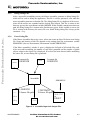
1.3
GETTING STARTED
This section describes how to use the MCUez tool chain. It provides instructions to:
•
Write an assembly source file
•
Assemble the assembly source file
•
Link the application to generate an executable file
1.3.1
Write An Assembly Source File
Freescale Semiconductor, Inc...
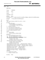
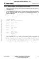
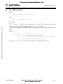
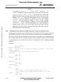
Once the project has been configured, you can start writing your application. For example,
your source code may be stored in a file named test.asm and may look as follows:
XDEF entry ; Make the symbol entry visible for external module.
; This is necessary to allow the linker to find the
; symbol and use it as the entry point for the
; application.
initStk: EQU $AFE
; Initial value for SP
cstSec: SECTION
; Define a constant relocatable section
var1:
DC.B 5
; Assign 5 to the symbol var1
dataSec: SECTION
; Define a data relocatable section
data:
DS.B 1
; Define one byte variable in RAM
codeSec: SECTION
; Define a code relocatable section
entry:
LDHX #initStk ; Load stack pointer
TXS
LDA
var1
INCA
STA
BRA
data
main
main:
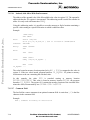
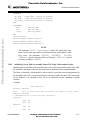
When writing assembly source code, pay special attention to the following points:
1-2
•
All symbols referenced outside the current source file (in another source file or in the
linker configuration file) must be externally visible. For this reason, we have inserted the
assembly directive XDEF entry.
•
In order to make debugging from the application easier, we strongly recommend you to
define separate sections for code, constant data (defined with DC), and variables (defined
with DS). This enables the symbols located in the variable or constant data sections to be
displayed in the data window component of the Debugger.
•
The stack pointer must be initialized when using BSR or JSR instructions in your
application.
For More Information On This Product,
Go to: www.freescale.com
MCUEZASM08/D
Freescale Semiconductor, Inc.
GENERAL INFORMATION
1.3.2
Assemble A Source File
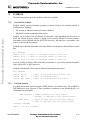
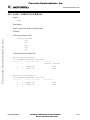
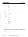
The following procedure describes how to assemble your source file.
Freescale Semiconductor, Inc...
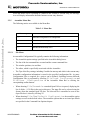
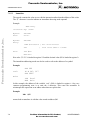
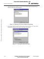
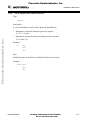
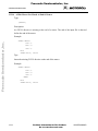
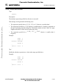
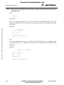
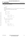
1. Start the macro assembler using the ezASM button in the MCUez shell. The figure below
is an example. Your dialog will reflect the release number of your package. Enter the name
of the file to be assembled in the editable combo box as shown below.
Figure 1-1. Assembler Window
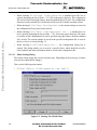
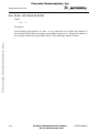
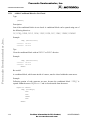
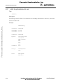
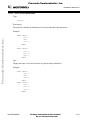
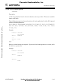
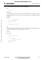
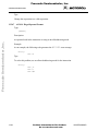
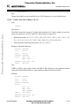
2. To generate an Elf/Dwarf 2 object file, the Assembler must be correctly set. Select menu
entry Assembler/Advanced. The Advanced Options Settings dialog is displayed:
Figure 1-2. Advanced Options Settings Dialog Box
MCUEZASM08/D
For More Information On This Product,
Go to: www.freescale.com
1-3
Freescale Semiconductor, Inc.
GENERAL INFORMATION
Freescale Semiconductor, Inc...
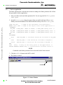
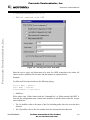
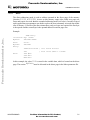
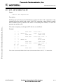
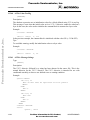
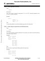
3. In the Output folder, select the check box in front of the label Object File
Format. More information is displayed at the bottom of the dialog. Select the radio
button ELF/DWARF 2.0 Object File Format and click OK. The
Assembler is now ready to generate an Elf /Dwarf 2 object file.
Figure 1-3. Selecting An Object File Format
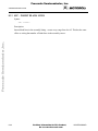
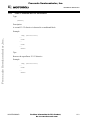
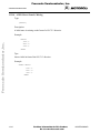
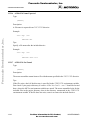
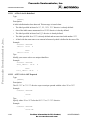
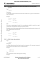
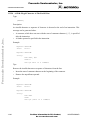
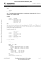
4. The file is assembled as soon as you click on the Assemble button:
Assemble Button
Figure 1-4. Assembling A File
1-4
For More Information On This Product,
Go to: www.freescale.com
MCUEZASM08/D
Freescale Semiconductor, Inc.
GENERAL INFORMATION
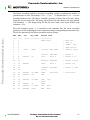
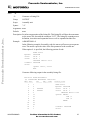
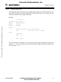
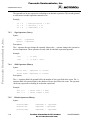
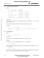
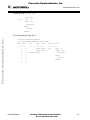
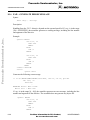
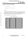
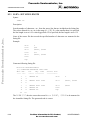
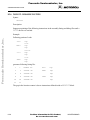
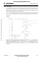
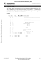
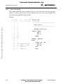
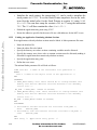
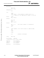
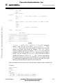
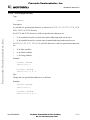
The Macro Assembler indicates successful assembling session by printing the number of
generated bytes of code. The message Code Size: 14 indicates that test.asm was
assembled without errors. The Macro Assembler generates a binary object file and a debug
listing file for each source file. The binary object file has the same name as the input module
with extension .o. The debug listing file has the same name as the input module, with
extension .dbg.
Freescale Semiconductor, Inc...
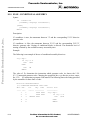
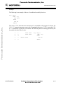
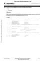
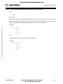
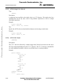
When the assembly option -L is specified on the command line, the macro assembler
generates a list file containing the source instruction and the corresponding hexadecimal code.
The list file generated by the Macro Assembler looks as follows:
Abs.
---1
2
3
4
5
6
7
8
9
10
11
12
13
14
15
16
17
18
19
20
21
22
Rel.
---1
2
3
4
5
6
7
8
9
10
11
12
13
14
15
16
17
18
19
20
21
22
MCUEZASM08/D
Loc
Obj.code
------ ---------
0000
000000
Source line
----------XDEF entry
0AFE
initStk: EQU $AFE
;
;
;
;
;
05
cstSec:
var1:
; Define a
; Assign 5 to
SECTION
DC.B 5
Make the
This is
symbol and
application.
Initial value
000000
dataSec: SECTION
data:
DS.B 1
; Define a data
; Define one
; Define a code
000000
000003
45 0AFE
94
codeSec: SECTION
entry:
LDHX
#initStk
TXS
000004
C6 xxxx
000007
000008
00000B
4C
C7 xxxx
20FA
; Load stack
LDA
var1
main:
INCA
STA
data
BRA
main
For More Information On This Product,
Go to: www.freescale.com
1-5
Freescale Semiconductor, Inc.
GENERAL INFORMATION
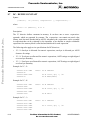
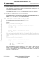
1.3.3
Link An Application
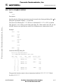
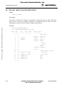
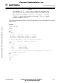
The linker organizes the code and data sections according to the linker parameter file. Follow
this procedure to link an application:
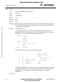
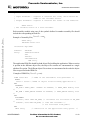
1. Start your editor and create linker parameter file. You can copy the file fibo.prm to
test.prm.
2. In the file test.prm , change the name of the executable and object files to test.
Modify start and end addresses for ROM and RAM memory areas. For test.prm:
Freescale Semiconductor, Inc...
LINK test.abs
/* Name of the executable file generated.*/
NAMES test.o END /* Name of the object files in the application */
SEGMENTS
MY_ROM = READ_ONLY 0x800 TO 0x8FF; /* READ_ONLY memory area. */
MY_RAM = READ_WRITE 0x0B0 TO 0x0FF; /* READ_WRITE memory area. */
MY_STK = READ_WRITE 0xA00 TO 0xAFF; /* READ_WRITE memory area. */
END
PLACEMENT
.data
INTO MY_RAM; /* Variables should be allocated in MY_RAM
*/
.text
INTO MY_ROM; /* Code should be allocated in MY_ROM */
.stack
INTO MY_STK; /* Stack will be allocated in MY_STK. */
END
INIT
entry /* entry is the entry point to the application. */
VECTOR ADDRESS 0xFFFE entry /* initialization for Reset vector.*/
NOTE
Commands in the linker parameter file are described in the Linker manual.
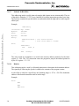
3. Click the ezLink button in the MCUez shell.
4. The Linker is started:
Link Button
Figure 1-5. Linker Window
1-6
For More Information On This Product,
Go to: www.freescale.com
MCUEZASM08/D
Freescale Semiconductor, Inc.
GENERAL INFORMATION
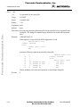
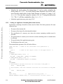
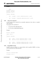
5. Type the name of the file to be linked in the editable combo box.
6. To start linking, press the Enter key or the Link button.
Freescale Semiconductor, Inc...
After you start the Linker, the window displays the link process:
Figure 1-6. Link Process In Action
MCUEZASM08/D
For More Information On This Product,
Go to: www.freescale.com
1-7
Freescale Semiconductor, Inc.
Freescale Semiconductor, Inc...
GENERAL INFORMATION
1-8
For More Information On This Product,
Go to: www.freescale.com
MCUEZASM08/D
Freescale Semiconductor, Inc.
GRAPHICAL USER INTERFACE
CHAPTER 2
GRAPHICAL USER INTERFACE
Freescale Semiconductor, Inc...
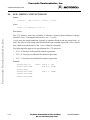
2.1
INTRODUCTION
Run the assembler from the MCUez shell by clicking the ezASM icon in the toolbar.
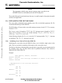
2.2
STARTING THE MOTOROLA ASSEMBLER
When the assembler is started, a standard Tip of the Day window containing a helpful hint
about using the assembler is displayed.
Figure 2-1. Tip Of The Day Window
Click Next Tip to see the next piece of information about the assembler. Click Close
to close the Tip of the Day dialog.
If you do not want to automatically open the standard Tip of the Day window when the
assembler is started, uncheck Show Tips on StartUp .
To re-enable the automatic display of this dialog at assembler start up, choose Help/Tip
of the Day.... The Tip of the Day dialog will be opened and you can check Show
Tips on StartUp.
MCUEZASM08/D
For More Information On This Product,
Go to: www.freescale.com
2-1
Freescale Semiconductor, Inc.
GRAPHICAL USER INTERFACE
2.3
ASSEMBLER GRAPHICAL INTERFACE
When no file name has been specified while starting the assembler, the following window is
displayed:
Window Title
Menu Bar
Freescale Semiconductor, Inc...
Toolbar
Content Area
Status Bar
Figure 2-2. Assembler Window
This window is only visible on the screen when you do not specify a file name while starting
the Assembler.
The Assembler window provides a window title, a menu bar, a toolbar, a content area, and a
status bar.
2.3.1
Window Title
The window title displays the Assembler name and the project name. If no project is currently
loaded, Default Configuration is displayed. A * after the configuration name indicates that
some values have been changed. The * indicates changes in options, editor configuration, or
appearance (window position, size, font,...).
2-2
For More Information On This Product,
Go to: www.freescale.com
MCUEZASM08/D
Freescale Semiconductor, Inc.
GRAPHICAL USER INTERFACE
2.3.2
Content Area
Freescale Semiconductor, Inc...
The Content Area is used as a text container where logging information about the assembly
session is displayed. This logging information contains:
•
Name of the file being assembled
•
Complete name (including full path) of the files processed (main assembly file and all
included files)
•
List of errors, warnings, and information messages generated
•
Size of the code generated during the assembly session
When a file name is dropped into the Assembly window content area, the corresponding file is
either loaded as configuration or assembled. It is loaded as configuration if the file has the
extension .ini. If not, the file is assembled with the current option settings (see the
Specifying The Input File section in this chapter).
All text in the Assembler window content area can have context information. The context
information consists of two items:
•
File name including a position inside of a file
•
Message number
File context information is available for all output lines where a file name is displayed. If a file
context is available for a line, double-clicking on this line opens the appropriate file in the
editor specified in your MCUez configuration. Double-clicking the right mouse button alos
opens a context menu. The menu contains an “Open ..” entry if a file context is available. If a
file can not be opened although a context menu entry is present, see the section Editor Settings
Dialog.
The message number is available for any message output. There are three ways to open the
corresponding entry in the help file:
•
Select one line of the message and press F1
•
Press Shift-F1 and then click on the message text
•
Click with the right mouse button at the message text and select Help on...
If you press F1 or Shift-F1 on a line that does not have a message number, the main Help file
opens. The Help on... item does not appear in the the right mouse button menu if there
is no message number associated with the message text.
Once an assembly session has completed, an error feedback can be performed automatically
by double clicking on the message in the content area. To allow error feedback, the desired
editor must be configured (see the Error Feedback section in this chapter).
MCUEZASM08/D
For More Information On This Product,
Go to: www.freescale.com
2-3
Freescale Semiconductor, Inc.
GRAPHICAL USER INTERFACE
2.3.3
Assembler Toolbar
The following figure shows the Assembler toolbar
:
Command Line
Assemble
Context Help
Stop Assembling
Freescale Semiconductor, Inc...
Help
Advanced Options
Save Configuration
Load Configuration
New Configuration
Figure 2-3. Assembler Toolbar
The three buttons on the left are linked with the corresponding entries of the File menu. The
New Configuration
, the Load Configuration
and the Save Configuration
enable
you to reset, load and save configuration files for the MCUez Assembler.
The Help button
Context Help.
and the Context Help button
enable you to open the Help file or the
When pressing
, the mouse cursor changes it’s form displaying a question mark beside the
arrow. A help file is called for the next item which is clicked. Specific help on menus, toolbar
buttons, or on the window areas are available.
The editable combo box contains the list of the last commands executed. Once a command
line has been selected or entered in the combo box, click the Assemble button
to execute
the command. The Stop Assembling button
enables you to abort the current assembly
session.
The Advanced Options button
2.3.4
enables you to open the Advanced Options dialog.
Status Bar
The following figure shows the Assembler Status Bar:
Message Area
Current Time
Figure 2-4. Assembler Status Bar
2-4
For More Information On This Product,
Go to: www.freescale.com
MCUEZASM08/D
Freescale Semiconductor, Inc.
GRAPHICAL USER INTERFACE
When the mouse arrow is pointing to a button in the Toolbar or a menu entry, the Message
Area will display information about the button or menu entry function.
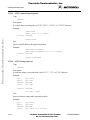
2.3.5
Assembler Menu Bar
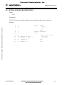
The following entries are available in the Menu Bar:
Table 2-1. Menu Bar
Freescale Semiconductor, Inc...
Menu entry
2.3.5.1
Description
File
Assembler Configuration File management.
Assembler
Assembler option settings.
View
Assembler window settings.
Help
Standard Windows Help menu.
File Menu
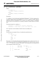
An assembler Configuration File typically contains the following information:
•
The Assembler option settings specified in the Assembler dialog boxes.
•
The list of the last command line executed and the current command line.
•
The window position, size and font.
•
The editor, which is specifically associated with the Assembler.
•
The Tips of the Day settings, including if enabled at start-up and which is the current entry
Assembler configuration information is stored in the specified configuration file. As many
Configuration Files as required for a project can be defined. Switching between different
Configuration Files is performed by choosing File/Load Configuration and
File/Save
Configuration in the Assembler Menu Bar or clicking the
corresponding toolbar buttons.
•
When choosing File/Assemble a standard Open File box is opened, displaying the
list of all the .ASM files in the project directory. The input file can be selected using the
features from the standard Open File box. The selected file is assembled as soon as the
Open File box is closed by clicking OK.
•
When choosing File/New/Default Configuration the assembler option
settings are reset to the default values. The assembler options that are activated per default
are specified in the Command Line Options chapter.
MCUEZASM08/D
For More Information On This Product,
Go to: www.freescale.com
2-5
Freescale Semiconductor, Inc.
Freescale Semiconductor, Inc...
GRAPHICAL USER INTERFACE
•
When choosing File/Load Configuration a standard Open File box is
opened, displaying the list of all the .INI files in the project directory. The configuration
file can be selected using the features from the standard Open File box. The configuration
data stored in the selected file is loaded and will be used by a further assembly session.
•
When choosing File/Save Configuration the current settings are stored in
the configuration file specified on the title bar.
•
When choosing File/Save Configuration As... a standard Save As
box is opened, displaying the list of all the .INI files in the project directory. The name
or location of the configuration file can be specified using the features from the standard
Save As box. The current settings are saved in the specified configuration file as soon as
the Save As box is closed clicking OK.
•
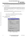
When choosing File/Configuration... the Configuration dialog box is
opened. This dialog enables you to specify a specific editor, which should be used for
error feedback and which information must be saved in the configuration file.
2.3.5.1.1
Editor Settings Dialog
The Editor Setting dialog has a main selection entry. Depending on the main type of editor
selected, the content below changes.
There are the following main entries:
•
Global Editor (Configured by the Shell)
Figure 2-5. Starting The Global Editor
2-6
For More Information On This Product,
Go to: www.freescale.com
MCUEZASM08/D
Freescale Semiconductor, Inc.
GRAPHICAL USER INTERFACE
This entry is only enabled (black) when an editor is configured in the “[Editor]” section from
the global initialization file MCUTOOLS.INI.
Freescale Semiconductor, Inc...
•
Local Editor (Configured by the Shell)
Figure 2-6. Starting The Local Editor
This entry is only enabled (black) when an editor is configured in the local configuration file,
usually project.ini in the project directory.
The Global and Local Editor configurations can be read with the Assembler, but not edited.
These entries can be configured with the MCUez Shell.
MCUEZASM08/D
For More Information On This Product,
Go to: www.freescale.com
2-7
Freescale Semiconductor, Inc.
GRAPHICAL USER INTERFACE
Freescale Semiconductor, Inc...
•
Editor started with Command Line
Figure 2-7. Starting The Editor With The Command Line
When this editor type is selected, a separate editor is associated with the Assembler for error
feedback. The editor configured in the Shell is not used for error feedback.
Enter the command that should be used to start the editor. Modifier can be specified in the
command line.See the note below for modifiers for file name and line number.
The format from the editor command depends on the syntax which should be used to start the
editor.
Example:
For Winedit 32 bit version use (with an adapted path to the winedit.exe file)
C:\WinEdit32\WinEdit.exe %f /#:%l
For Write.exe use (with an adapted path to the write.exe file, note that write does not support
line number).
C:\Winnt\System32\Write.exe %f
For Motpad.exe use (with an adapted path to the Motpad.exe file, note that Motpad supports
line number).
2-8
For More Information On This Product,
Go to: www.freescale.com
MCUEZASM08/D
Freescale Semiconductor, Inc.
GRAPHICAL USER INTERFACE
C:\TOOLS\MOTPAD\MOTPAD.exe %f::%l
Freescale Semiconductor, Inc...
•
Editor started with DDE
Figure 2-8. Starting The Editor With DDE
Enter the service, topic, and client name to be used for a DDE connection to the editor. All
entries can have modifiers for file name and line number as explained below.
Example:
For Microsoft Developer Studio use the following setting :
Service Name : "msdev"
Topic Name : "system"
ClientCommand : "[open(%f)]"
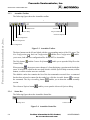
•
Modifiers
When either entry ‘Editor Started with the Command line’ or ‘Editor started with DDE’ is
selected, the configurations may contain some modifiers to tell the editor which file to open
and at which line:
•
The %f modifier refers to the name of the file (including path) where the error has been
detected
•
The %l modifier refers to the line number where the message has been detected
MCUEZASM08/D
For More Information On This Product,
Go to: www.freescale.com
2-9
Freescale Semiconductor, Inc.
GRAPHICAL USER INTERFACE
The format from the editor command depends on the syntax used to start the editor. Please
check your editor manual to define the command line which should be used to start the editor.
2.3.5.1.2
Important Remarks
Freescale Semiconductor, Inc...
Caution should be taken using %l: this modifier can only be used with an editor which can be
started with a line number as a parameter. Editors such as WinEdit version 3.1 or lower, and
Notepad do not allow this kind of parameter. This kind of editor can be started using the file
name as a parameter. Choosing the menu entry Go To will jump to the line where the error
has been detected.
In that case the Command Line looks like: C:\WINAPPS\WINEDIT\Winedit.EXE %f
Check your editor manual to define the Command Line used to start the editor.
NOTE
If you are using a word processing editor (Microsoft Word, Wordpad,...),
make sure you save your input file as ASCII text file, otherwise the
Assembler will have trouble to process them.
2.3.5.1.3
Configuration Dialog
The following figure shows the Configuration dialog:
Figure 2-9. Configuration Dialog
2-10
For More Information On This Product,
Go to: www.freescale.com
MCUEZASM08/D
Freescale Semiconductor, Inc.
GRAPHICAL USER INTERFACE
Save operation options are contained on the Save Configuration page of the Configuration
dialog. In the Save Configuration dialog, you can control the configuration items to be saved:
•
Options: when this mark is set, the current option settings are stored in the
configuration files. By disabling this option, the last saved settings remain valid
•
Editor Configuration: when this mark is set, the current editor setting are
stored in a configuration file. By disabling this options, the last saved content remains
valid.
Freescale Semiconductor, Inc...
•
Appearance (Position, Size, Font): When this mark is set, the
window position (loaded at start-up), command line content, and command line history
settings are saved in the configuration file. By disabling this option, the previous settings
remains valid.
NOTE
By disabling selective options only some parts of a configuration file can
be written. For example when the best Assembler options are found, the
save option mark can be removed. Then future save commands will not
modify the options any more.
•
Save on Exit: If this option is set, the Assembler will write the configuration on
exit. No question will appear to confirm this operation. If this option is not set, the
Assembler will not write the configuration at exit, even if options or another part of the
configuration has changed. No confirmation will appear in any case when closing the
Assembler
NOTE
Most settings are stored in the configuration file, but the list of recently
used configurations and the settings in the Save Configuration dialog are
stored in the assembler section of MCUTOOLS.INI.
MCUEZASM08/D
For More Information On This Product,
Go to: www.freescale.com
2-11
Freescale Semiconductor, Inc.
GRAPHICAL USER INTERFACE
2.3.5.2
Assembler Menu
This menu allows you to customize and set Assembler options:
•
Assembler/Advanced defines the options to be activated when assembling an
input file.
•
Freescale Semiconductor, Inc...
2.3.5.3
Assembler/Stop Assembly immediately stops the current assembly session.
View Menu
This menu enables you to customize the Assembler window. You can hide or display the
Status Bar and Toolbar, define the window font, and clear the window. Choose:
View/Toolbar to hide or display the Assembler Window Toolbar
• View/Statusbar to hide or display the Assembler Window Status Bar
•
View/Log... to customize the output in the Assembler Window Content Area
• View/Log.../Change Font to open a standard Font Selection box that
•
changes the font in the Assembler Window Content Area
•
2.3.6
View/Log.../Clear Log to clear the Assembler Window Content Area
Advanced Options Settings Dialog Box
This dialog box enables you to set/reset assembler options, as shown in the figure below:
Figure 2-10. Advanced Options Settings Dialog Box
2-12
For More Information On This Product,
Go to: www.freescale.com
MCUEZASM08/D
Freescale Semiconductor, Inc.
GRAPHICAL USER INTERFACE
The available options are arranged in different groups:
Table 2-2. Advanced Options
Freescale Semiconductor, Inc...
Option Group
Description
Output
Lists options related to the output files (type of files to be generated).
Input
Lists options related to the input file.
Host
Lists options related to the host.
Code Generation
Lists options related to code generation (memory models,...).
Messages
Lists options that control error message generation.
To set an assembly option, click the box to the left of the option. When you select an option
that requires additional parameters, an edit box or subwindow opens and prompts you for the
additional information.
The Assembler options specified in project files (using the MCUez shell) are automatically
displayed in the Advanced Options Settings dialog.
2.3.7
Specifying The Input File
The input file to be assembled can be specified in several ways. During the assembly session,
the options will be set according to the configuration provided by the user in the Advanced
Options Settings dialog box. Before assembling a file make sure you have associated a Project
Directory with your assembler.
You can specify the input file through the Editable Combo box, the Assemble item in the File
menu, or by using the “drag and drop” feature.
2.3.7.1
Editable Combo Box
Use the Editable Combo Box in the Assembler Toolbar to:
•
Assemble a new file - enter a new file name and Assembler options in the command line
•
Assemble a previously assembled file - click the pull-down arrow to the right of the
Editable Combo Box and choose from the list of previously assembled files that appears
To assemble the file you have indicated, select the Assemble button.
2.3.7.2
File/Assemble
Choose File/Assemble to open a standard Open File box. Browse and select the
desired file. When you click the Open button, the previous dialog is closed and the selected
file is assembled.
MCUEZASM08/D
For More Information On This Product,
Go to: www.freescale.com
2-13
Freescale Semiconductor, Inc.
GRAPHICAL USER INTERFACE
2.3.7.3
Drag And Drop
Use the “drag and drop” feature to “drag” a file from an external source and “drop” it into the
Assembler Window. A file dropped in the Assembler Window is immediately assembled
unless the file has an “.ini” extension. Files with an “.ini” extension are considered
configuration files and are immediately loaded, not assembled. To assemble a source file with
an “.ini” extension, use the Editable Combo Box, or the Assemble item from the File
Menu.
Freescale Semiconductor, Inc...
2.3.8
Error Feedback
After a source file has been assembled, you can view the detected errors and warnings in
several ways. The error message format is:
‘>> <FileName>, line <line number>, col <column number>, pos <absolute position in file>
<Portion of code generating the problem>
<message class> <message number>: <Message string>‘
Example:
>> in “C:\DEMO\fiboerr.asm”, line 76, col 20, pos 1932
BRA label
^
ERROR A1104: Undeclared user defined symbol: label
2.3.8.1
Error Feedback Using Information From The Assembler Window
Once a file has been assembled, the Assembler Window Content Area displays a list of all the
errors or warnings detected. Any editor can be used to open the source file and correct errors.
2.3.8.2
Error Feedback From A User-Defined Editor
The editor for Error Feedback must be configured through the MCUez Shell or the
Configuration dialog box. The Error Feedback process differs from editor to editor, depending
on the editor’s ability to start from a line number in the Command Line.
2.3.8.2.1
Editors That Can Start With A Line Number On The Command Line
Editors like Motpad, WinEdit (v.95 or higher) or Codewright can be started with a line
number in the command line. When these editors have been correctly configured, they can be
activated automatically by double clicking on an error message. The configured editor will be
started, the file where the error occurs is automatically opened and the cursor is placed on the
line where the error was detected.
2-14
For More Information On This Product,
Go to: www.freescale.com
MCUEZASM08/D
Freescale Semiconductor, Inc.
GRAPHICAL USER INTERFACE
2.3.8.2.2
Editors That Cannot Start With A Line Number On The Command Line
Editors such as WinEdit (v.31 or lower), Notepad, and Wordpad cannot be started with a line
number in the command line. When these editors have been correctly configured, they can be
activated automatically by double-clicking an error message. The configured editor will be
started, the file where the error occurs is automatically opened. To scroll to the position where
the error was detected:
1. Activate the Assembler
Freescale Semiconductor, Inc...
2. Click the line that generated the message error (the line is highlighted on the screen)
3. Press Ctrl-C to copy the line
4. Activate the editor
5. Select Search/Find to open the Find dialog box
6. Press Ctrl-V to paste the line in the Edit box
7. Click Forward to jump to the error’s position
MCUEZASM08/D
For More Information On This Product,
Go to: www.freescale.com
2-15
Freescale Semiconductor, Inc.
Freescale Semiconductor, Inc...
GRAPHICAL USER INTERFACE
2-16
For More Information On This Product,
Go to: www.freescale.com
MCUEZASM08/D
Freescale Semiconductor, Inc.
ENVIRONMENT
CHAPTER 3
ENVIRONMENT
Freescale Semiconductor, Inc...
3.1
INTRODUCTION
This part of the manual describes the environment variables used by the Assembler. Some of
the environment variables are also used by other tools (e.g. Linker).
Various parameters of the Assembler may be set in an environment using environment
variables. The syntax is always the same:
KeyName=ParamDef
Example:
GENPATH=C:\INSTALL\LIB;D:\PROJECTS\TEST
NOTE
No blanks are allowed before and after the “=” character in the definition
of an environment variable.
These parameters may be defined in several ways:
•
Using system environment variables supported by your operating system.
•
Putting the definitions in a file called DEFAULT.ENV (.hidefaults for UNIX)
in the default directory.
•
Putting the definitions in a file set by the system environment variable ENVIRONMENT.
NOTE
The default directory can be set via environment variable DEFAULTDIR.
When looking for an environment variable, all programs first search the system environment,
then the DEFAULT.ENV (.hidefaults for UNIX) file and finally the global
environment file given by ENVIRONMENT. If no definition can be found, a default value is
assumed.
NOTE
The environment may also be changed using the -Env Assembler option.
MCUEZASM08/D
For More Information On This Product,
Go to: www.freescale.com
3-1
Freescale Semiconductor, Inc.
ENVIRONMENT
3.2
PATHS
Most environment variables contain path lists telling where to look for files. A path list is a list
of directory names separated by semicolons following the syntax below:
PathList = DirSpec {“;” DirSpec}.
DirSpec = [“*”] DirectoryName.
Example:
Freescale Semiconductor, Inc...
GENPATH=C:\INSTALL\LIB;D:\PROJECTS\TESTS
If a directory name is preceded by an asterisk (“*”), the programs recursively search the
complete directory tree for a file, not just the given directory itself. The directories are
searched in the order they appear in the path list.
Example:
LIBPATH=*C:\INSTALL\LIB
We strongly recommend working with MCUez shell and setting the environment by means of
a DEFAULT.ENV file in your project directory (This “project dir.” can be set in
the MCUez shell configure dialog box. This way, you can have different projects in different
directories, each with its own environment.
Some environment variables have a synonym that may be used compatibly with older releases
of the assembler.
3.3
LINE CONTINUATION
You can define an environment variable over different lines using the line continuation
character, “\”:
ASMOPTIONS=\
-W2 \
-WmsgNe=10
is the same as:
ASMOPTIONS=-W2 -WmsgNe=10
Line Continuation may be dangerous when used with paths. The code:
GENPATH=.\
TEXTFILE=.\txt
will result in:
GENPATH=.TEXTFILE=.\txt
To avoid such problems, use a semicolon, “;”, at the end of a path if there is a “\” at the end
of the code line such as:
GENPATH=.\;
TEXTFILE=.\txt
3-2
For More Information On This Product,
Go to: www.freescale.com
MCUEZASM08/D
Freescale Semiconductor, Inc.
ENVIRONMENT
3.4
ENVIRONMENT VARIABLES DESCRIPTIONS
The remainder of this section is devoted to describing each of the environment variables
available for the Assembler. The environment variables are listed in alphabetical order and are
divided into the sections described in the chart below.
Freescale Semiconductor, Inc...
Topic
Description
Synonym
For some environment variables a synonym also exists. Those
synonyms may be used for older releases of the Assembler and will
be removed in the future. A synonym has lower precedence than the
environment variable.
Syntax
Specifies the syntax of the environment variable in a EBNF format.
Arguments
Describes and lists optional and required arguments for the variable.
Default
Shows the default setting for the variable.
Description
Provides a detailed description of the environement variable and how
to use it.
Example
Gives an example of usage, and effects of the variable where
possible. The examples show an entry in the default.env.
See Also
Names related sections.
MCUEZASM08/D
For More Information On This Product,
Go to: www.freescale.com
3-3
Freescale Semiconductor, Inc.
ENVIRONMENT
3.4.1
ASMOPTIONS
Synonym:
None
Syntax:
“ASMOPTIONS=” {<option>}
Arguments: <option>: Assembler command line option
Freescale Semiconductor, Inc...
Description: If this environment variable is set, the Assembler appends its contents to its
command line each time a file is assembled. It can be used to globally specify
certain options that should always be set, so you don’t have to specify them each
time a file is assembled.
Options enumerated here must be valid assembler options and are separated by
space characters.
3.4.2
Example:
ASMOPTIONS=-W2 -L
See Also:
Assembler Options chapter in this manual.
GENPATH
Synonym:
HIPATH
Syntax:
“GENPATH=” {<path>}
Arguments: <path>: Paths separated by semicolons, without spaces.
Description: The macro assembler will look for the source or included files first in the project
directory, then in the directories listed in the environment variable GENPATH.
NOTE
If a directory specification in this environment variable starts with an
asterisk (“*”), the entire directory tree is searched recursively, i.e. all
subdirectories and their subdirectories are searched. Within one level in the
tree, search order of the subdirectories is indeterminate (not valid for
Win32).
3-4
Example:
GENPATH=\sources\include;...\...\headers;
See Also:
None
For More Information On This Product,
Go to: www.freescale.com
MCUEZASM08/D
Freescale Semiconductor, Inc.
ENVIRONMENT
3.4.3
ABSPATH
Synonym:
None
Syntax:
“ABSPATH=” {<path>}
Arguments: <path>: Paths separated by semicolons, without spaces.
Freescale Semiconductor, Inc...
Description: This environment variable is only relevant when absolute files are directly
generated by the macro assembler instead of object files. When this environment
variable is defined, the Assembler will store the absolute files it produces in the
first directory specified. If ABSPATH is not set, the generated absolute files will
be stored in the directory where the source file was found.
3.4.4
Example:
ABSPATH=\sources\bin;..\..\headers;
See Also:
None
OBJPATH
Synonym:
None
Syntax:
“OBJPATH=” {<path>}
Arguments: <path>: Paths separated by semicolons, without spaces.
Description: When this environment variable is defined, the assembler will store the object
files it produces in the first directory specified. If OBJPATH is not set, the
generated object files will be stored in the directory where the source file was
found.
3.4.5
Example:
OBJPATH=\sources\bin;..\..\headers;
See Also:
None
TEXTPATH
Synonym:
None
Syntax:
“TEXTPATH=” {<path>}
Arguments: <path>: Paths separated by semicolons, without spaces.
Description: When this environment variable is defined, the assembler will store the listing
files it produces in the first directory specified. If TEXTPATH is not set, the
generated listing files will be stored in the directory where the source file was
found.
Example:
TEXTPATH=\sources\txt;..\..\headers;
See Also:
None
MCUEZASM08/D
For More Information On This Product,
Go to: www.freescale.com
3-5
Freescale Semiconductor, Inc.
ENVIRONMENT
3.4.6
SRECORD
Synonym:
None
Syntax:
“SRECORD=” <RecordType>
Arguments: <Record Type>: Force the type for the Motorola S record which must be
generated. This parameter may take the value “S1”, “S2”, or “S3”.
Freescale Semiconductor, Inc...
Description: This environment variable is only relevant when absolute files are directly
generated by the macro assembler instead of object files. When this environment
variable is defined, the Assembler will generate a Motorola S file containing
records from the specified type (S1 records when S1 is specified, S2 records when
S2 is specified and S3 records when S3 is specified).
When the SRECORD variable is not set, the type of S record generated will
depend on the size of the target address space that is loaded. If the address space
can be coded on 2 bytes, an S1 record is generated. If the address space is coded
on 3 bytes, an S2 record is generated. Otherwise, an S3 record is generated.
NOTE
If the environment variable SRECORD is set, it is the user responsibility to
specify the appropriate S record type. If you specify S1 while your code is
loaded above 0xFFFF, the Motorola S file generated will not be correct,
because the addresses will all be truncated to 2 byte values.
3-6
Example:
SRECORD=S2
See Also:
None
For More Information On This Product,
Go to: www.freescale.com
MCUEZASM08/D
Freescale Semiconductor, Inc.
ENVIRONMENT
3.4.7
ERRORFILE
Synonym:
None
Syntax:
“ERRORFILE=” <filename>
Arguments: <filename>: File name with possible format specifiers.
Description: The environment variable ERRORFILE specifies the name for the error file (used
by the Compiler or assembler).
Possible format specifiers are:
Freescale Semiconductor, Inc...
'%n': Substitute with the file name, without the path.
'%p': Substitute with the path of the source file.
'%f': Substitute with the path and name (the same as '%p%n').
In case of an illegal error file name, a notification box is shown.
Example:
ERRORFILE=MyErrors.err
Lists all errors into the file “MyErrors.err” in the current directory.
ERRORFILE=\tmp\errors
Lists all errors into the file “errors” in the directory \tmp.
ERRORFILE=%f.err
Lists all errors into a file with the same name as the source file (with extension
.err) into the same directory as the source file. For example, if you assemble a
file \sources\test.asm, an error list file \sources\test.err
will be generated.
ERRORFILE=\dir1\%n.err
Generates an error list file, file \dir1\test.err, for a source file
test.asm.
ERRORFILE=%p\errors.txt
Generates an error list file, \dir1\dir2\errors.txt, for a source file
\dir1\dir2\test.asm.
If the environment variable ERRORFILE is not set, the errors are written to the
default error file. The default error file name is dependent upon how the
assembler is configured and started. If a file name is provided in the assembler
command line, errors are written to the EDOUT file (to the name-specified file)
in the project directory. If no file name is provided, errors are written to the
ERR.TXT file in the project directory.
MCUEZASM08/D
For More Information On This Product,
Go to: www.freescale.com
3-7
Freescale Semiconductor, Inc.
ENVIRONMENT
Example:
Another example shows the usage of this variable to support correct error
feedback with the WinEdit Editor which looks for an error file called
EDOUT:
Installation directory: E:\INSTALL\PROG
Project sources: D:\MEPHISTO
Common Sources for projects: E:\CLIB
Entry in default.env (D:\MEPHISTO\DEFAULT.ENV):
ERRORFILE=E:\INSTALL\PROG\EDOUT
Freescale Semiconductor, Inc...
Entry in WINEDIT.INI (in Windows directory):
OUTPUT=E:\INSTALL\PROG\EDOUT
See Also:
3-8
None
For More Information On This Product,
Go to: www.freescale.com
MCUEZASM08/D
Freescale Semiconductor, Inc.
ENVIRONMENT
3.4.8
INCLUDETIME: Creation Time In Object File
Synonym:
None
Syntax:
“INCLUDETIME=” (“ON” | “OFF”)
Arguments: “ON”: Include time information into object file.
“OFF”: Do not include time information into object file.
Freescale Semiconductor, Inc...
Default:
“ON”
Description: Normally each object file created contains a time stamp indicating the creation
time and data as strings. So whenever a new file is created by one of the tools, the
new file gets a new time stamp entry.
This behavior may be undesired if for SQA reasons a binary file compare has to
be performed. Even if the informations in two object files are the same, the files
do not match exactly because the time stamps are not the same. To avoid such
problems this variable may be set to OFF. In this case the time stamp strings in
the object file for date and time are “none” in the object file.
The time stamp may be retrieved from the object files using a decoder.
Example:
INCLUDETIME=OFF
See also:
Environment variable COPYRIGHT
Environment variable USERNAME
3.4.9
USERNAME: User Name In Object File
Synonym:
None
Syntax:
“USERNAME=” <user>
Arguments: <user>: Name of user.
Default:
None
Description: Each object file contains an entry identifying the user who created the object file.
This information may be retrieved from the object files using a decoder.
Example:
USERNAME=HIWARE AG, CH-4058 Basel
See Also:
Environment variable COPYRIGHT
Environment variable INCLUDETIME
MCUEZASM08/D
For More Information On This Product,
Go to: www.freescale.com
3-9
Freescale Semiconductor, Inc.
Freescale Semiconductor, Inc...
ENVIRONMENT
3-10
For More Information On This Product,
Go to: www.freescale.com
MCUEZASM08/D
Freescale Semiconductor, Inc.
FILES
CHAPTER 4
FILES
Freescale Semiconductor, Inc...
4.1
INTRODUCTION
This chapter describes all file types associated with the MCUez application.
4.2
INPUT FILES
The Assembler accepts two forms of input files:
•
Source Files
•
Include Files
4.2.1
Source Files
The macro assembler takes any file as input and does not require the file name to have a
special extension. Source files will be searched first in the project directory and then in the
GENPATH directory.
4.2.2
Include File
The search for include files is governed by the environment variable GENPATH. Include files
are searched first in the project directory, then in the directories given in the environment
variable GENPATH. The project directory is set via MCUez shell or the environment variable
DEFAULTDIR.
4.3
OUTPUT FILES
The Assembler produces six different types of output files:
•
Object Files
•
Absolute Files
•
Motorola S Files
•
Listing Files
•
Debug Listing Files
•
Error Listing Files
MCUEZASM08/D
For More Information On This Product,
Go to: www.freescale.com
4-1
Freescale Semiconductor, Inc.
FILES
4.3.1
Object Files
After a successful assembling session, the Macro Assembler generates an object file
containing the target code as well as some debugging information. This file is written to the
directory given in the environment variable OBJPATH. If that variable contains more than one
path, the object file is written in the first directory given. If this variable is not set, the object
file is written in the directory the source file was found. Object files always get the extension
.o.
Freescale Semiconductor, Inc...
4.3.2
Absolute Files
When an application is encoded in a single module and all the sections are absolute sections,
the user can decide to generate an absolute file instead of an object file. This file is written to
the directory given in the environment variable ABSPATH. If that variable contains more than
one path, the absolute file is written in the first directory given. If this variable is not set, the
absolute file is written in the directory the source file was found. Absolute files always get the
extension .abs.
4.3.3
Motorola S Files
When an application is encoded in a single module and all the sections are absolute sections,
the user can decide to generate an absolute file instead of an object file. In that case, a
Motorola S record file is generated at the same time. This file can be burnt into an EPROM. It
contains information stored in all READ_ONLY sections in the application. The extension for
the generated Motorola S record file depends on the setting from the variable SRECORD.
•
If SRECORD = S1, the Motorola S record file gets the extension .s1.
•
If SRECORD = S2, the Motorola S record file gets the extension .s2.
•
If SRECORD = S3, the Motorola S record file gets the extension .s3.
•
If SRECORD is not set, the Motorola S record file gets the extension .sx.
This file is written to the directory given in the environment variable ABSPATH. If that
variable contains more than one path, the motorola S file is written in the first directory given.
If this variable is not set, the file is written in the directory the source file was found.
4.3.4
Listing Files
After a successful assembling session, the Macro Assembler generates a listing file containing
each assembly instruction with its associated hexadecimal code. This file is generated as soon
as the option -L is activated, even when the macro assembler generates an absolute file. This
file is written to the directory given in the environment variable TEXTPATH. If that variable
contains more than one path, the listing file is written in the first directory given. If this
variable is not set, the listing file is written in the directory the source file was found. Listing
files always get the extension .lst. The Assembler Listing File chapter in this manual
describes the format of this file.
4-2
For More Information On This Product,
Go to: www.freescale.com
MCUEZASM08/D
Freescale Semiconductor, Inc.
FILES
4.3.5
Debug Listing Files
Freescale Semiconductor, Inc...
After a successful assembling session, the Macro Assembler generates a debug listing file,
which will be used to debug the application. This file is always generated, even when the
macro assembler generates an absolute file. The debug listing file is a duplicate of the source,
where all the macros are expanded and the include files merged. This file is written to the
directory given in the environment variable OBJPATH. If that variable contains more than one
path, the debug listing file is written in the first directory given. If this variable is not set, the
file is written in the directory the source file was found. Debug listing files always get the
extension .dbg.
4.3.6
Error Listing File
If the Macro Assembler detects any errors, it does not create an object file but an error listing
file. Name and location of this file depends on the settings from the environment variable
ERRORFILE (also see Environment, Environment Variable ERRORFILE).
If the Macro assembler’s window is open, it displays the full path of all include files read.
After successful assembling, the number of code bytes generated and the number of global
objects written to the object file is displayed. If an error has been detected while assembling
the source file, an error listing file is generated.
1.current dir
.asm 2.GENPATH
.inc
1.current dir
2.GENPATH
Assembler
ERRORFILE
.o
1.OBJPATH
2.Source file path
.abs
.dbg
.lst
1.TEXTPATH
2.Source file path
ERR.TXT
or
EDOUT
Figure 4-1. Assembler Input And Output Files
MCUEZASM08/D
For More Information On This Product,
Go to: www.freescale.com
4-3
Freescale Semiconductor, Inc.
Freescale Semiconductor, Inc...
FILES
4-4
For More Information On This Product,
Go to: www.freescale.com
MCUEZASM08/D
Freescale Semiconductor, Inc.
ASSEMBLER OPTIONS
CHAPTER 5
ASSEMBLER OPTIONS
Freescale Semiconductor, Inc...
5.1
INTRODUCTION
The Assembler offers a number of options that you can use to control the Assembler
operation. Options are composed of a minus/dash, “-”, followed by one or more letters or
digits. Anything not starting with a minus/dash is assumed to be the name of a source file to be
assembled. Assembler options may be specified on the command line or in the
ASMOPTIONS environment variable. Typically, each Assembler option is specified only
once per assembling session.
NOTE
Arguments for an option must not exceed 128 characters.
Command line options are not case sensitive. “–Li” is the same as “–li”. To facilitate
specifying several options belonging to the same group, e.g. “–Lc” and “–Li”, the
Assembler allows coalescing options in the same group, i.e. “–Lci” or “–Lic” instead of
“–Lc –Li”.
NOTE
It is not possible to coalesce options in different groups, e.g. “–Lc –W1”
cannot be abbreviated by the terms “–LC1” or “–LCW1”.
5.2
ASMOPTIONS
If this environment variable is set, the Assembler appends its contents to its command line
each time a file is assembled. It can be used to globally specify certain options that should
always be set, so you don’t have to specify them each time a file is assembled. Assembler
options are grouped as follows:
MCUEZASM08/D
5-1
For More Information On This Product,
Go to: www.freescale.com
Freescale Semiconductor, Inc.
ASSEMBLER OPTIONS
Table 5-1. Assembler Option Groups
Freescale Semiconductor, Inc...
Group
Description
HOST
Lists options related to the host.
OUTPUT
Lists options related to output file generation (which type of file to be
generated).
INPUT
Lists options related to the input file
CODE
Lists options related to code generation (memory models, float
format,...).
INPUT
Lists options related to input file processing (which type of file is
processed).
MESSAGE
Lists options controlling generation of error messages.
The group corresponds to the property sheets of the graphical option settings.
Scope of each option:
Table 5-2. Assembler Scope Groups
Scope
Description
Application
The option has to be set for all files (Assembly Units) of an
application. A typical example is an option to set the memory model.
Mixing object files will have unpredictable results.
Assembly Unit
This option can be set differently for each assembling unit of an
application. Mixing objects in an application is possible.
None
The option scope is not related to a specific code part. A typical
example is options for the message management.
The available options are arranged into different groups, and a sheet is available for each of
these groups. The content of the list box depends on the selected sheets.
5-2
For More Information On This Product,
Go to: www.freescale.com
MCUEZASM08/D
Freescale Semiconductor, Inc.
ASSEMBLER OPTIONS
5.3
ASSEMBLER OPTION DESCRIPTIONS
The remainder of this section describes each of the assembler options available for the
assembler. The options are listed in alphabetical order and described by the following
sections.
Table 5-3. Assembler Option Details
Freescale Semiconductor, Inc...
Topic
Description
Group
HOST, OUTPUT, CODE, INPUT, MESSAGE, or VARIOUS (options
in the some of the groups cannot be selected through the Advanced
Options Settings Dialog).
Scope
Application, Assembly Unit, or None.
Syntax
Specifies the syntax of the option in a EBNF format.
Arguments
Describes and lists optional and required arguments for the option.
Default
Shows the default setting for the option.
Description
Provides a detailed description of the option and how to use it.
Example
Gives an example of usage, and effects of the option where possible.
Assembler settings, source code and/or Linker PRM files are
displayed where applicable. The examples show an entry in the
default.env for PC or in the .hidefaults for UNIX.
See Also
Related options.
MCUEZASM08/D
For More Information On This Product,
Go to: www.freescale.com
5-3
Freescale Semiconductor, Inc.
ASSEMBLER OPTIONS
5.3.1
-Ci
-CI: Set Case Sensivity On Label Names OFF
Group:
INPUT
Scope:
Assembly Unit
Syntax:
"-CI" .
Arguments: None
Freescale Semiconductor, Inc...
Default:
None
Description: This switches case sensitivity on label names OFF. When this option is activated,
the assembler do not care about case sensitivity for label name.
This options can only be specified when the assembler generates directly absolute
file (Option -FA2 must be activated).
Example:
When case sensitivity on label names is switched off, the assembler will not
generate any error message for following code:
ORG $200
entry: NOP
BRA Entry
The instruction ‘BRA Entry’ will branch on the label ‘entry’. Per default, the
assembler is case sensitive on label names. For the assembler the label ‘Entry’
and ‘entry’ are two distinct labels.
See also:
5.3.2
P&E to MCUeZ Assembler Converter manual.
-Env
Set Environment Variable
Group:
HOST
Scope:
Assembly Unit
Syntax:
“-Env” <EnvironmentVariable> “=” <VariableSetting>
Arguments: <EnvironmentVariable>: Environment variable to be set.
<VariableSetting>: Variable setting.
Default:
None
Description: Sets an environment variable.
Example:
ASMOPTIONS=-EnvOBJPATH=\sources\obj
This is the same as:
OBJPATH=\sources\obj
in the default.env
See Also:
5-4
Environment
For More Information On This Product,
Go to: www.freescale.com
MCUEZASM08/D
Freescale Semiconductor, Inc.
ASSEMBLER OPTIONS
5.3.3
-F2/-FA2
Object File Format
Group:
OUTPUT
Scope:
Application
Syntax:
“-F2”/ “-FA2”).
Arguments: “-F2”: ELF/DWARF 2.0 object file format
“-FA2”: ELF/DWARF 2.0 absolute file format (default setting)
Freescale Semiconductor, Inc...
Default:
-FA2
Description: Defines the format for the output file generated by the Assembler.
With the option -F2 set, the Assembler produces an ELF/DWARF object file.
With the option -FA2 set, the Assembler produces an ELF/DWARF absolute
file.
Example:
ASMOPTIONS=-FA2
See Also:
None
MCUEZASM08/D
For More Information On This Product,
Go to: www.freescale.com
5-5
Freescale Semiconductor, Inc.
ASSEMBLER OPTIONS
5.3.4
-H
Short Help
Group:
VARIOUS
Scope:
None
Syntax:
“-H”
Arguments: None
Default:
None
Freescale Semiconductor, Inc...
Description: The -H option causes the Assembler to display a short list of available options.
Example:
-H may produce the following list:
HOST:
-Env Set environment variable (-Env<envVar>=<value>)
OUTPUT:
-F
Object File Format
-FA2: ELF/DWARF 2.0 Absolute File
-F2: ELF/DWARF 2.0 Object File Format
-L
Generate a listing file
-Lc Do not print macro call in list file
-Ld Do not print macro definition in list file
-Le Do not print macro expansion in list file
-Li Do not print included files in list file
CODE:
-M
Memory Model
-Ms: Small Memory Model (default)
MESSAGE:
-N
Show notification box in case of errors
-W1 Don't print INFORMATION messages
-W2 Don't print INFORMATION or WARNING messages
-WmsgFb Set message file format for batch mode
-WmsgFbv: verbose format
-WmsgFbm: Microsoft format (default)
-WmsgFi Set message format for interacitve mode
-WmsgFiv: Verbose format (default)
-WmsgFim: Microsoft format
-WmsgNe Maximum number of errors
(-WmsgNe<number>), default 50
-WmsgNi Maximum number of informations (-WmsgNi<number>), default 50
-WmsgNw Maximum number of warnings (-WmsgNw<number>), default 50
-WmsgSd Set message to disable (-WmsgSd<number>)
-WmsgSe Set message to error
(-WmsgSe<number>)
-WmsgSi Set message to information (-WmsgSi<number>)
-WmsgSw Set message to warning (-WmsgSw<number>)
VARIOUS:
-H
Prints this list of options
-V
Prints the assembler version
See Also:
5-6
None
For More Information On This Product,
Go to: www.freescale.com
MCUEZASM08/D
Freescale Semiconductor, Inc.
ASSEMBLER OPTIONS
5.3.5
-L
-L:
Generates a Listing File
Group:
OUTPUT
Scope:
Assembly unit
Syntax:
"-L"
Arguments: none
Freescale Semiconductor, Inc...
Default:
none
Description: Switches on generation of the listing file. This listing file will have the same name
as the source file, but with the extension “.LST”. The listing file contains macro
definition, invocation and expansion lines as well as expanded include files.
Example:
ASMOPTIONS=-L
In the following example of assembly code, the macro cpChar accept two parameters. The macro copies the value of the first parameter to the second one.
When option -L is specified, the following portion of code
XDEF Start
SECTION
DS.B 1
DS.B 1
INCLUDE "macro.inc"
CodeSec: SECTION
Start:
cpChar char1, char2
NOP
MyData:
char1:
char2:
Generates following output in the assembly listing file:
Motorola HC08-Assembler
(c) COPYRIGHT MOTOROLA 1991-1997
Abs. Rel.
Loc
Obj. code
Source line
---- --------- ------------------1
1
XDEF Start
2
2
MyData: SECTION
3
3
000000
char1: DS.B 1
4
4
000001
char2: DS.B 1
5
5
INCLUDE "macro.inc"
6
1i
cpChar: MACRO
7
2i
LDA \1
8
3i
STA \2
9
4i
ENDM
10
5i
11
6i
12
6
CodeSec: SECTION
13
7
Start:
MCUEZASM08/D
For More Information On This Product,
Go to: www.freescale.com
5-7
Freescale Semiconductor, Inc.
ASSEMBLER OPTIONS
14
15
16
17
18
8
2m
3m
9
10
000000
000003
000006
000007
C6 xxxx
C7 xxxx
9D
9D
+
+
cpChar char1, char2
LDA char1
STA char2
NOP
NOP
Content of included files, as well as macro definition, invocation and expansion
are stored in the listing file. Refer to Chapter 10, “Assembler Listing File,” for
detailed information.
Freescale Semiconductor, Inc...
See also:
5-8
Li, Lc, Ld, Le
For More Information On This Product,
Go to: www.freescale.com
MCUEZASM08/D
Freescale Semiconductor, Inc.
ASSEMBLER OPTIONS
5.3.6
-Lc
-Lc:
No Macro Call in Listing File
Group:
OUTPUT
Scope:
Assembly unit
Syntax:
"-Lc"
Arguments: none
Freescale Semiconductor, Inc...
Default:
none
Description: Switches on generation of the listing file, but macro invocations are not present in
the listing file. The listing file contains macro definition and expansion lines as
well as expanded include files.
Example:
ASMOPTIONS=-Lc
In the following example of assembly code, the macro cpChar accept two
parameters. The macro copies the value of the first parameter to the second one.
When option -Lc is specified, following portion of code
cpChar: MACRO
LDA \1
STA \2
ENDM
codeSec: SECTION
Start:
cpChar char1, char2
NOP
NOP
generates following output in the assembly listing file:
5
6
7
8
9
10
12
13
14
15
5
6
7
8
9
10
6m
7m
12
13
000000
000003
000006
000007
C6 xxxx
C7 xxxx
9D
9D
cpChar:MACRO
LDA \1
STA \2
ENDM
CodeSec:SECTION
Start:
+
LDA char1
+
STA char2
NOP
NOP
Content of included files, macro definition and expansion are stored in the list file.
The source line containing the invocation of the macro is not present in the listing
file. Refer to Chapter 10, “Assembler Listing File,” for detailed information.
See also:
MCUEZASM08/D
L
For More Information On This Product,
Go to: www.freescale.com
5-9
Freescale Semiconductor, Inc.
ASSEMBLER OPTIONS
5.3.7
-Ld
-Ld:
No Macro Definition in Listing File
Group:
OUTPUT
Scope:
Assembly unit
Syntax:
"-Ld"
Arguments: none
Default:
none
Freescale Semiconductor, Inc...
Description: Switches on generation of the listing file, but macro definitions are not present in
the listing file. The listing file contains macro invocation and expansion lines as
well as expanded include files.
Example:
ASMOPTIONS=-Ld
In the following example of assembly code, the macro cpChar accept two
parameters. The macro copies the value of the first parameter to the second one.
When option -Ld is specified, the following portion of code
cpChar:
MACRO
LDA \1
STA \2
ENDM
codeSec: SECTION
Start:
cpChar char1, char2
NOP
NOP
main:
BRA main
generates following output in the assembly listing file:
5
9
10
11
12
13
14
15
5
9
10
11
6m
7m
12
13
000000
000003
000006
000007
C6 xxxx
C7 xxxx
9D
9D
cpChar: MACRO
codeSec: SECTION
Start:
cpChar char1, char2
+
LDA char1
+
STA char2
NOP
NOP
Content of included files, as well as macro invocation and expansion are stored in
the listing file. The source code from the macro definition is not present in the
listing file. Refer to Chapter 10, “Assembler Listing File,” for detailed
information.
See also:
5-10
L
For More Information On This Product,
Go to: www.freescale.com
MCUEZASM08/D
Freescale Semiconductor, Inc.
ASSEMBLER OPTIONS
5.3.8
-Le
-Le:
No Macro Expansion in Listing File
Group:
OUTPUT
Scope:
Assembly unit
Syntax:
"-Le"
Arguments: none
Freescale Semiconductor, Inc...
Default:
none
Description: Switches on generation of the listing file, but macro expansions are not present in
the listing file. The listing file contains macro definition and invocation lines as
well as expanded include files.
Example:
ASMOPTIONS=-Le
In the following example of assembly code, the macro cpChar accept two
parameters. The macro copies the value of the first parameter to the second one.
When option -Le is specified, the following portion of code
cpChar: MACRO
LDA \1
STA \2
ENDM
codeSec: SECTION
Start:
cpChar char1, char2
NOP
NOP
generates following output in the assembly listing file:
5
6
7
8
9
10
11
14
15
5
6
7
8
9
10
11
12
13
cpChar:
000006 9D
000007 9D
MACRO
LDA \1
STA \2
ENDM
CodeSec: SECTION
Start:
cpChar char1, char2
NOP
NOP
Content of included files, as well as macro definition and invocation are stored in
the listing file. The macro expansion lines are not present in the listing file. Refer
to Chapter 10, “Assembler Listing File,” for detailed information.
See also:
MCUEZASM08/D
L
For More Information On This Product,
Go to: www.freescale.com
5-11
Freescale Semiconductor, Inc.
ASSEMBLER OPTIONS
5.3.9
-Li
-Li:
No included File in Listing File
Group:
OUTPUT
Scope:
Assembly unit
Syntax:
"-Li"
Arguments: none
Default:
none
Freescale Semiconductor, Inc...
Description: Switches on generation of the listing file, but include files are not expanded in the
listing file. The listing file contains macro definition, invocation and expansion
lines.
Example:
ASMOPTIONS=-Li
When option -Li is specified, the following portion of code
INCLUDE "macro.inc"
codeSec: SECTION
Start:
cpChar char1, char2
NOP
generates following output in the assembly listing file:
5
10
11
12
13
14
15
16
5
6
7
8
2m
3m
9
10
000000
000003
000006
000007
C6 xxxx
C7 xxxx
9D
9D
INCLUDE "macro.inc"
CodeSec: SECTION
Start:
cpChar char1, char2
+
LDA char1
+
STA char2
NOP
NOP
Macro definition, invocation and expansion is stored in the listing file.
See also:
5-12
L
For More Information On This Product,
Go to: www.freescale.com
MCUEZASM08/D
Freescale Semiconductor, Inc.
ASSEMBLER OPTIONS
5.3.10
-Ms/-Mb
Memory Model
Group:
CODE
Scope:
Application
Syntax:
“-Ms” / “-Mb”
Arguments: “-Ms”: small memory model.
“-Mb”: banked memory model.
Freescale Semiconductor, Inc...
Default:
-Ms
Description: The Assembler for the MC68HC08 supports two different memory models.
Default is the small memory model, which corresponds to the normal setup, i.e. a
64kB code-address space. If you use some code memory expansion scheme, you
may use banked memory model.
Example:
ASMOPTIONS=-Ms
See Also:
None
MCUEZASM08/D
For More Information On This Product,
Go to: www.freescale.com
5-13
Freescale Semiconductor, Inc.
ASSEMBLER OPTIONS
5.3.11
-N
Display Notify Box
Group:
MESSAGE
Scope:
Function
Syntax:
“-N”
Arguments: None
Default:
None
Freescale Semiconductor, Inc...
Description: Makes the Assembler display an alert box if there was an error during assembling.
This is useful when running a makefile, since the Assembler waits for the user to
acknowledge the message, thus suspending makefile processing. ( “N” stands for
“Notify”)
Example:
ASMOPTIONS=-N
If an error occurs during assembling, a dialog box indicating that an error
occurred is opened as shown below:
See Also:
5-14
None
For More Information On This Product,
Go to: www.freescale.com
MCUEZASM08/D
Freescale Semiconductor, Inc.
ASSEMBLER OPTIONS
5.3.12
-V
Display Assembler Version
Group:
VARIOUS
Scope:
None
Syntax:
“-V”
Arguments: None
Freescale Semiconductor, Inc...
Default:
None
Description: Prints the Assembler version and the current directory. This option is useful to
determine the current directory of the Assembler.
Example:
-V produces the following list:
Directory: C:\MCUEZ\DEMO\WMMDS08A
CCPP User Interface Module, V-1.0.4, Date Jul 10 1997
Assembler Target, V-1.0.11, Date Jul 11 1997
See Also:
MCUEZASM08/D
None
For More Information On This Product,
Go to: www.freescale.com
5-15
Freescale Semiconductor, Inc.
ASSEMBLER OPTIONS
5.3.13
-W1
Block Information Messages
Group:
MESSAGE
Scope:
Assembly Unit
Syntax:
“-W1”
Arguments: None
Default:
None
Freescale Semiconductor, Inc...
Description: Blocks INFORMATION messages. WARNING and ERROR messages are still
active.
5-16
Example:
ASMOPTIONS=-W1
See Also:
None
For More Information On This Product,
Go to: www.freescale.com
MCUEZASM08/D
Freescale Semiconductor, Inc.
ASSEMBLER OPTIONS
5.3.14
-W2
Block Information and Warning Messages
Group:
MESSAGE
Scope:
Assembly Unit
Syntax:
“-W2”
Arguments: None
Freescale Semiconductor, Inc...
Default:
None
Description: Blocks INFORMATION and WARNING messages. Only ERROR messages are
active.
Example:
ASMOPTIONS=-W2
See Also:
None
MCUEZASM08/D
For More Information On This Product,
Go to: www.freescale.com
5-17
Freescale Semiconductor, Inc.
ASSEMBLER OPTIONS
5.3.15
-WmsgNe
Number of Error Messages
Group:
MESSAGE
Scope:
Assembly Unit
Syntax:
“-WmsgNe” <number>
Arguments: <number>: Maximum number of error messages.
Default:
50
Freescale Semiconductor, Inc...
Description: Sets the number of errors that can be encountered before the Assembler stops
processing.
Example:
ASMOPTIONS=-WmsgNe2
The Assembler stops assembling after two error messages.
See Also:
5-18
-WmsgNi
-WmsgNw
For More Information On This Product,
Go to: www.freescale.com
MCUEZASM08/D
Freescale Semiconductor, Inc.
ASSEMBLER OPTIONS
5.3.16
-WmsgNi
Number of Information Messages
Group:
MESSAGE
Scope:
Assembly Unit
Syntax:
“-WmsgNi”<number>
Arguments: <number>: Maximum number of information messages.
Default:
50
Freescale Semiconductor, Inc...
Description: Sets the maximum number of information messages to be logged.
Example:
ASMOPTIONS=-WmsgNi10
Only ten information messages can be logged.
See Also:
MCUEZASM08/D
-WmsgNe
-WmsgNw
For More Information On This Product,
Go to: www.freescale.com
5-19
Freescale Semiconductor, Inc.
ASSEMBLER OPTIONS
5.3.17
-WmsgNw
Number of Warning Messages
Group:
ASSEMBLY
Scope:
Assembly Unit
Syntax:
“-WmsgNw” <number>
Arguments: <number>: Maximum number of warning messages.
Default:
50
Freescale Semiconductor, Inc...
Description: Sets the maximum number of warning messages to be logged.
Example:
ASMOPTIONS=-WmsgNw15
Only 15 warning messages can be logged.
See Also:
5-20
-WmsgNe
-WmsgNi
For More Information On This Product,
Go to: www.freescale.com
MCUEZASM08/D
Freescale Semiconductor, Inc.
ASSEMBLER OPTIONS
5.3.18
-WmsgFbv/ -WmsgFbm
Set message file format for batch mode
Group:
MESSAGE
Scope:
Assembly Unit
Syntax:
“-WmsgFbv”/ “-WmsgFbm”]
Arguments: “-WmsgFbv”: Verbose format.
“-WmsgFbm”: Microsoft format.
Freescale Semiconductor, Inc...
Default:
-WmsgFbm
Description: The Assembler can be started with additional arguments (e.g. files to be
assembled together with Assembler options). If the Assembler has been started
with arguments (e.g. from the Make Tool or with the ‘%f’ argument from
WinEdit), the Assembler assembles the files in a batch mode, that is no Assembler
window is visible and the Assembler terminates after job completion.
If the assembler is in batch mode the assembler messages are written to a file
instead to the screen. This file only contains the assembler messages. By default,
the Assembler uses a Microsoft message format to write the Assembler messages
(errors, warnings, information messages) if the assembler is in batch mode.
With this option, the default format may be changed from the Microsoft format to
a more verbose error format with line, column, and source information.
Example:
var1:
equ
5
var2:
equ
5
if (var1=var2)
nop
endif
endif
By default, the Assembler generates following error output in the Assembler
window if it is running in batch mode:
X:\TW2.ASM(12):ERROR: conditional else not allowed here
Setting the format to verbose, more information is stored in the file:
ASMOPTIONS=-WmsgFbv
>> in "X:\TW2.ASM", line 12, col 0, pos 215
endif
endif
^
ERROR A1001: Conditional else not allowed here
See Also:
MCUEZASM08/D
-WmsgFi
For More Information On This Product,
Go to: www.freescale.com
5-21
Freescale Semiconductor, Inc.
ASSEMBLER OPTIONS
5.3.19
-WmsgFiv/-WmsgFim
-WmsgFi: Set message file format for Interactive mode
Group:
MESSAGE
Scope:
Assembly Unit
Syntax:
“-WmsgFiv” / “-WmsgFim”
Arguments: “-WmsgFiv”: Verbose format
“-WmsgFim”: Microsoft format
Freescale Semiconductor, Inc...
Default:
-WmsgFiv
Description: If the Assembler is started without additional arguments (e.g. files to be
assembled together with Assembler options), the Assembler is in the interactive
mode (that is, a window is visible). By default, the Assembler uses the verbose
errorfileformattowritetheAssemblermessages(errors,warnings,informationmessages).
With this option, the default format may be changed from the verbose format
(with source, line and column information) to the Microsoft format (only line
information).
Example:
var1:
equ
5
var2:
equ
5
if (var1=var2)
nop
endif
endif
By default, the Assembler following error output in the Assembler window if it is
running in interactive mode
>> in "X:\TWE.ASM", line 12, col 0, pos 215
endif
endif
^
ERROR A1001: Conditional else not allowed here
Setting the format to Microsoft, less information is displayed:
ASMOPTIONS=-WmsgFim
X:\TWE.ASM(12): ERROR: conditional else not allowed here
See Also:
5-22
-WmsgFb
For More Information On This Product,
Go to: www.freescale.com
MCUEZASM08/D
Freescale Semiconductor, Inc.
SECTIONS
CHAPTER 6
SECTIONS
Freescale Semiconductor, Inc...
6.1
INTRODUCTION
Sections are portions of code or data which cannot be split into smaller elements. Each section
has a name, type, and attributes. Each assembly source file contains at least one section.
The number of sections in an assembly source file is limited only by the amount of available
system memory available during assembly. If several sections with the same name are
detected inside a single source file, the code is concatenated into one large section.
Sections that have the same name but come from different modules are combined into a single
section when linked.
6.2
SECTION ATTRIBUTE
According to content, an attribute is associated with each section. A section may be a:
6.2.1
•
Data section
•
Constant data section
•
Code section
Data Sections
A section containing variables (variable defined using the DS directive) is considered to be a
data section. Data sections are always allocated in the target processor RAM area.
Empty sections, which do not contain any code or data declaration are also considered to be
data sections.
6.2.2
Constant Data Sections
A section containing only constant data definitions (variables defined using the DC or DCB
directives) is considered to be a constant section. Constant sections should be allocated in the
target processor ROM area, otherwise they cannot be initialized at application loading time.
We strongly recommend that you define separate sections for the definition of variables and
constant variables. This will avoid any problems in the initialization of constant variables.
MCUEZASM08/D
For More Information On This Product,
Go to: www.freescale.com
6-1
Freescale Semiconductor, Inc.
SECTIONS
6.2.3
Code Sections
A section containing at least an instruction is considered to be a code section. Code sections
are always allocated in the target processor ROM area.
Code sections should not contain any variable definition (variable defined using the DS
directive). You will not have write access on variables defined in a code section. Additionally,
these variables cannot be displayed in the debugger as data.
Freescale Semiconductor, Inc...
6.3
SECTION TYPE
First a programmer should decide whether he wants to use relocatable or absolute code in his
application. The Assembler allows you to mix absolute and relocatable sections in a single
application and also in a single source file. The main difference between absolute and
relocatable sections is the way symbol addresses are determined.
6.3.1
Absolute Sections
Start address from an absolute section is well known at assembly time. An absolute section is
defined through the directive ORG. The operand specified in the ORG directive determines
the start address of the absolute section.
XDEF entry
ORG $040
cst1: DC.B
$26
cst2: DC.B
$BC
...
ORG $080
var: DS.B
1
; Absolute constant data section.
; Absolute data section.
ORG $C00
; Absolute code section.
LDA
ADD
STA
BRA
; Load value in cst1
; Add value in cst2
; Store in var
entry:
cst1
cst2
var
entry
In the previous example, two bytes of storage are allocated starting at address $040. Symbol
“cst1” will be allocated at address $040 and “cst2” will be allocated at address $041. All
subsequent instructions or data allocation directives will be located in the absolute section
until another section is specified using the ORG or SECTION directive.
When using absolute sections, it is the user responsibility to ensure that there is no overlap
between the different absolute sections defined in the application. In the previous example, the
programmer should ensure that the size of the section starting at address $040 is not bigger
than $40 bytes, otherwise the section starting at $040 and section starting at $080 will overlap.
6-2
For More Information On This Product,
Go to: www.freescale.com
MCUEZASM08/D
Freescale Semiconductor, Inc.
SECTIONS
When object files are generated, applications containing only absolute sections must be
linked. In that case, there should not be any overlap between the address ranges from the
absolute sections defined in the assembly file and the address ranges defined in the linker
parameter file.
Freescale Semiconductor, Inc...
The PRM file used to link the example above, is defined as follows:
LINK test.abs /* Name of the executable file generated. */
NAMES
test.o
/* Name of the object files in the application. */
END
SEGMENTS
/* READ_ONLY memory area. There should be no overlap between this
memory area and the absolute sections defined in the assembly
source file. */
MY_ROM = READ_ONLY 0x1000 TO 0x1FFF;
/* READ_WRITE memory area. There should be no overlap between this
memory area and the absolute sections defined in the assembly
source file. */
MY_RAM = READ_WRITE 0x2000 TO 0x2FFF;
END
PLACEMENT
/* Relocatable variable sections are allocated in MY_RAM. */
.data
INTO MY_RAM;
/*Relocatable code and constant sections are allocated in MY_ROM. */
.text
INTO MY_ROM;
END
INIT entry
/* Application entry point. */
VECTOR ADDRESS 0xFFFE entry /* initialization of the reset vector.
*/
MCUEZASM08/D
For More Information On This Product,
Go to: www.freescale.com
6-3
Freescale Semiconductor, Inc.
SECTIONS
Freescale Semiconductor, Inc...
The linker PRM file contains at least:
•
The name of the absolute file (command LINK)
•
The name of the object file which should be linked (command NAMES)
•
The specification of a memory area where the sections containing variables must be
allocated and at least the predefined section, “ .data”, must be placed (command
SEGMENTS and PLACEMENT)
•
The specification of a memory area where the sections containing code or constants must
be allocated and at least the predefined section, “.text”, must be placed (command
SEGMENTS and PLACEMENT)
•
The specification of the application entry point (command INIT)
•
The definition of the reset vector (command VECTOR ADDRESS)
For applications containing only absolute sections, nothing will be allocated.
6.3.2
Relocatable Sections
Start address from a relocatable section is evaluated at linking time, according to the
information stored in the linker parameter file. A relocatable section is defined through the
directive SECTION.
XDEF entry
constSec: SECTION
cst1:
DC.B $A6
cst2:
DC.B $BC
...
dataSec: SECTION
var:
DS.B 1
codeSec:
entry:
; Relocatable constant data section.
; Relocatable data section.
SECTION
; Relocatable code section.
LDA
ADD
STA
BRA
; Load value in cst1
; Add value in cst2
; Store in var
cst1
cst2
var
entry
In the previous example, two bytes of storage are allocated in section “constSec”.
Symbol “cst1” will be allocated at offset 0 and “cst2” at offset 1 from the begining of
the section. All subsequent instructions or data allocation directives will be located in the
relocatable section “constSec” until another section is specified using the ORG or
SECTION directive.
6-4
For More Information On This Product,
Go to: www.freescale.com
MCUEZASM08/D
Freescale Semiconductor, Inc.
SECTIONS
When using relocatable sections, the user does not need to care about overlapping sections.
The linker will assign a start address to each section according to the input from the linker
parameter file.
Freescale Semiconductor, Inc...
The customer can decide to define only one memory area for the code and constant sections
and another one for the variable sections or to split sections over several memory areas. When
all constant and code sections as well as data sections can be allocated consecutively, the PRM
file used to assemble the example above, can be defined as follows:
LINK test.abs /*Name of the executable file generated. */
NAMES
test.o
/*Name of the object files in the application. */
END
SEGMENTS
/* READ_ONLY memory area. */
MY_ROM = READ_ONLY 0x0B00 TO 0x0BFF;
/* READ_WRITE memory area. */
MY_RAM = READ_WRITE 0x0080 TO 0x008F;
END
PLACEMENT
/* Relocatable variable sections are allocated in MY_RAM. */
.data
INTO MY_RAM;
/*Relocatable code and constant sections are allocated in
MY_ROM. */
.text
INTO MY_ROM;
END
INIT entry
/* Application entry point. */
VECTOR ADDRESS 0xFFFE entry /* initialization of the reset
vector. */
According to the PRM file above:
•
The section “dataSec” will be allocated starting at 0x080
•
The section “constSec” will be allocated starting at 0x0B00
•
The section “codeSec” will be allocated next to the section “constSec”
MCUEZASM08/D
For More Information On This Product,
Go to: www.freescale.com
6-5
Freescale Semiconductor, Inc.
SECTIONS
Freescale Semiconductor, Inc...
When the constant, code, and data sections cannot be allocated consecutively, the PRM file
used to link the example above, can be defined as follows:
LINK test.abs /* Name of the executable file generated. */
NAMES
test.o
/* Name of the object files in the application. */
END
SEGMENTS
ROM_AREA_1= READ_ONLY 0xB00 TO 0xB7F; /*READ_ONLY memory area. */
ROM_AREA_2= READ_ONLY 0xC00 TO 0xC7F; /*READ_ONLY memory area. */
RAM_AREA_1= READ_WRITE 0x800 TO 0x87F; /*READ_WRITE memory area.*/
RAM_AREA_2= READ_WRITE 0x900 TO 0x97F; /*READ_WRITE memory area.*/
END
PLACEMENT
/*Relocatable variable sections are allocated in MY_RAM. */
dataSec
INTO RAM_AREA_2;
.data
INTO RAM_AREA_1;
/*Relocatable code and constant sections are allocated in MY_ROM. */
constSec
INTO ROM_AREA_2;
codeSec, .text INTO ROM_AREA_1;
END
INIT entry
/* Application entry point. */
VECTOR ADDRESS 0xFFFE entry /*initialization of the reset vector. */
According to the PRM file above:
6.3.3
•
The section “dataSec” will be allocated starting at 0x0900
•
The section “constsec” will be allocated starting at 0x0C00
•
The section “codeSec” will be allocated starting at 0x0B00
Relocatable Versus Absolute Section
Generally we recommend developing an application using relocatable sections. Relocatable
sections offer several advantages.
6.3.3.1
Early Development
The application can be developed before the application memory map is known. Often the
definitive application memoy map can only be determined once the size required for code and
data can be evaluated. The size required for code or data can only be quantified once the major
part of the application is implemented. When absolute sections are used, defining the
definitive memory map is an iterative process of mapping and remapping the code. The
assembly files must be edited, assembled and linked several times. When relocatable sections
are used, this can be achieved by editing the PRM file and linking the application.
6-6
For More Information On This Product,
Go to: www.freescale.com
MCUEZASM08/D
Freescale Semiconductor, Inc.
SECTIONS
6.3.3.2
Enhanced Portability
As the memory map is not the same for all derivates (MCU), using relocatable sections allow
you to easily port the code for another MCU. When porting relocatable code to another target
you only need to link the application again, with the appropriate memory map.
Freescale Semiconductor, Inc...
6.3.3.3
Tracking Overlaps
When using absolute sections, the programmer must ensure there is no overlap between
sections. When using relocatable sections, the programmer does not need to be concerned
about sections overlapping. The labels’ offsets are all evaluated relative to the beginning of
the section. Absolute addresses are then determined and assigned by the linker.
6.3.3.4
Reusability
When using relocatable sections, code implemented to handle a specific I/O device (serial
communication device), can be reused in another application without any modification.
MCUEZASM08/D
For More Information On This Product,
Go to: www.freescale.com
6-7
Freescale Semiconductor, Inc.
Freescale Semiconductor, Inc...
SECTIONS
6-8
For More Information On This Product,
Go to: www.freescale.com
MCUEZASM08/D
Freescale Semiconductor, Inc.
ASSEMBLER SYNTAX
CHAPTER 7
ASSEMBLER SYNTAX
Freescale Semiconductor, Inc...
7.1
INTRODUCTION
An assembler source program is a sequence of source statements. Each source statement is
coded on one line of text and can be a:
•
Comment line
•
Source line
7.1.1
Comment Line
A comment can occupy an entire line to explain the purpose and usage of a block of
statements or to describe an algorithm. A comment line contains a semicolon followed by
text. Comments are included in the assembly listing, but are not significant to the assembler.
An empty line is also considered to be a comment line.
Example:
; This is a comment line
7.1.2
Source Line
Each source statement includes one or more of the following four fields:
•
A label
•
An operation field
•
One or several operands
•
A comment
Characters on the source line may be upper or lower case. Directives and instructions are case
insensitive. Symbols are case-sensitive except when the Ci, an option specifying caseinsensitivity for label names, is activated.
7.1.3
Label Field
The label field is the first field in a source line. A label is a symbol followed by a colon.
Labels can include letters, underscores, periods, and numbers. The first character must not be
a number.
MCUEZASM08/D
For More Information On This Product,
Go to: www.freescale.com
7-1
Freescale Semiconductor, Inc.
ASSEMBLER SYNTAX
Labels are required on assembler directives that define the value of a symbol (SET or EQU).
For these directives, labels are assigned the value corresponding to the expression in the
operand field.
Labels specified in front of another directive, instruction or comment are assigned the value of
the location counter in the current section.
Freescale Semiconductor, Inc...
NOTE
When the macro assembler expands a macro it generates internal symbols
starting with an “_”. Therefore, to avoid potential conflicts, user defined
symbols should not begin with an underscore.
NOTE
For the macro assembler, a .B at the end of a label means “byte” and a .W
at the end of a label means “word”. Therefore, to avoid potential conflicts,
user defined symbols should not end with .B or .W.
7.1.4
Operation Field
The operation field follows the label field and is separated from it by a white space. The
operation field must not begin in the first column. An entry in the operation field is one of the
following:
7.1.4.1
•
An instruction mnemonic
•
A directive name
•
A macro name
Instruction
Executable instructions for the M68HC08 processor are defined in CPU08 Reference Manual,
document number CPU08RM/AD.
7.1.4.2
Directive
Assembler directives are described in the Assembler Directives chapter in this manual.
7.1.4.3
Macro Name
A user-defined macro can be invoked in the assembler source program. This results in the
expansion of the code defined in the macro. Defining and using macros are described in the
Macros chapter in this manual.
7-2
For More Information On This Product,
Go to: www.freescale.com
MCUEZASM08/D
Freescale Semiconductor, Inc.
ASSEMBLER SYNTAX
7.1.5
Operand Field
The operand fields, when present, follows the operation field and is separated from it by a
white space. When two or more operand subfields appear within a statement, a comma must
separate them. The following addressing mode notations are allowed in the operand field:
Table 7-1. Addressing Mode Notations
Freescale Semiconductor, Inc...
Addressing Mode
Notation
Inherent
No operands
Direct
<8-bit address>
Extended
<16-bit address>
Relative
<PC relative offset>
Immediate
#<expression>
Indexed, no offset
,X
Indexed, 8-bit offset
<8-bit offset>,X
Indexed, 16-bit offset
<16-bit offset>,X
Stack pointer, 8-bit offset
<8-bit offset>,SP
Stack pointer, 16-bit offset
<16-bit offset>,SP
Memory to memory immediate to direct
#<expression>,<8-bit address>
Memory to memory direct to direct
<8-bit address>,<8-bit address>
Memory to memory indexed to direct with
post-increment
X+,<8-bit address>
7.1.5.1
Inherent
Instructions using this addressing mode don’t have any instruction fetch associated. Some of
them are acting on data in the CPU registers.
Example:
CLRA
DAA
MCUEZASM08/D
For More Information On This Product,
Go to: www.freescale.com
7-3
Freescale Semiconductor, Inc.
ASSEMBLER SYNTAX
7.1.5.2
Immediate
The opcode contains the value to use with the instruction rather than the address of this value.
The “#” character is used to indicate an immediate adressing mode operand.
Example:
Freescale Semiconductor, Inc...
XDEF Entry
initStack: EQU $0400
MyData:
data:
SECTION
DS.B 1
MyCode:
Entry:
SECTION
LDHX #initStack ; init Stack Pointer
TXS
; with value $400-1 = $03FF
main:
LDA #$50
BRA main
Hex value $0400 is loaded in register HX and the decimal value $50 is loaded in register A.
The immediate addressing mode can also be used to refer to the address of a symbol.
Example
var1:
ORG $80
DC.B $45, $67
ORG $800
main:
LDX #var1
BRA main
In this example, the address of the variable ‘var1’ ($80) is loaded in register X. One very
common programming error is to omit the # character. This cause the assembler to
misinterpret the expression as an addres rather than an explicit data.
Example
LDA
$60
means load accumulator A with the value stored at address $60.
7-4
For More Information On This Product,
Go to: www.freescale.com
MCUEZASM08/D
Freescale Semiconductor, Inc.
ASSEMBLER SYNTAX
7.1.5.3
Direct
The direct addressing mode is used to address operands in the direct page of the memory
(location $0000 to $00FF). Access on this memory range (also called zero page) are
faster and require less code than the extended addressing mode (see below). In order to speed
up his application a programmer can decide to place the most commonly accessed data in this
area of memory. For most of the direct instructions, only two bytes are required: the first byte
is the opcode and the second byte is the operand address located in page zero.
Freescale Semiconductor, Inc...
Example:
XDEF Entry
initStack: EQU $0400
MyData:
SECTION SHORT
data:
DS.B 1
MyCode:
SECTION
Entry:
LDHX #initStack ; init Stack Pointer
TXS
; with value $400-1 = $03FF
main:
LDA #$55
STA data
BRA main
In this example, the value $55 is stored in the variable data, which is located on the direct
page. The section MyData must be allocated in the direct page in the linker parameter file.
MCUEZASM08/D
For More Information On This Product,
Go to: www.freescale.com
7-5
Freescale Semiconductor, Inc.
ASSEMBLER SYNTAX
7.1.5.4
Extended
The extended addressing mode is used to access memory location located above the direct
page in a 64-Kilobyte memory map. For the extended instructions, three bytes are required:
the first byte is the opcode and the second and the third bytes are the most and least significant
bytes of the operand address.
Freescale Semiconductor, Inc...
Example:
XDEF Entry
initStack: EQU $0400
ORG $B00
data:
DS.B 1
MyCode:
SECTION
Entry:
LDHX #initStack ; init Stack Pointer
TXS
; with value $400-1 = $03FF
main:
LDA #$55
STA data
BRA main
In this example, the value $55 is stored in the variable data. This variable is located at
address $0B00 in the memory map. The opcode of the instruction STA data is three
bytes long.
7.1.5.5
Indexed, No Offset
This addressing mode is used to access data with variable addresses through the index register
HX of the HC08 controller. The index register X contains the least significant byte of the
operand while index register H contains the most significant byte. Indexed, no offset
instructions are one byte long.
Example:
...
Entry:
...
LDHX #$0FFE
STA
,X
...
JMP
,X
...
The value stored in accumulator A is stored at the memory address pointed to by the index
register X ($0FFE). The JMP instruction causes the program to jump to the address pointed
to by the HX register.
7-6
For More Information On This Product,
Go to: www.freescale.com
MCUEZASM08/D
Freescale Semiconductor, Inc.
ASSEMBLER SYNTAX
7.1.5.6
Indexed, 8-Bit Offset
This addressing mode is useful when selecting the kth element in an n-element table. The size
of the table is limited to 256 bytes. Indexed, 8-bit offset instructions are two bytes long. The
first byte contains the index register offset byte.
Freescale Semiconductor, Inc...
Example:
XDEF Entry
initStack: EQU $0400
MyData:
SECTION SHORT
data:
DS.B 8
MyCode:
SECTION
Entry:
LDHX #initStack ; init Stack Pointer
TXS
; with value $400-1 = $03FF
main:
LDHX #data
STA
5 ,X
...
JMP
$FF,X
...
The value stored in accumulator A is stored at the memory address pointed to by the index
register X + 5. The JMP instruction causes the program to jump to the address pointed to by
the HX register + $FF.
MCUEZASM08/D
For More Information On This Product,
Go to: www.freescale.com
7-7
Freescale Semiconductor, Inc.
ASSEMBLER SYNTAX
7.1.5.7
Indexed, 16-Bit Offset
This addressing mode is useful when selecting the kth element in an n-element table. The size
of the table is limited to $FFFF bytes. Indexed,16-bit offset instructions are three bytes long.
The first byte contains the opcode and the second and the third the high and low index register
offset bytes.
Freescale Semiconductor, Inc...
Example:
XDEF Entry
initStack: EQU $0400
MyData:
SECTION
data:
DS.B 8
MyCode:
SECTION
Entry:
LDHX #initStack ; init Stack Pointer
TXS
; with value $400-1 = $03FF
main:
LDHX #data
STA
$500 ,X
...
JMP
$1000,X
...
The value stored in accumulator A is stored at the memory address pointed to by the index
register X + 500 . The JMP instruction causes the program to jump to the address pointed to
by the HX register + $1000.
7.1.5.8
Relative
This addressing mode is used by all branch instructions to determine the destination address.
The signed byte following the opcode is added to the contents of the program counter.
As the offset is coded on a signed byte, the branching range is -127 to +128. The destination
address of the branch instruction must be in this range.
Example:
main:
NOP
NOP
BRA main
7-8
For More Information On This Product,
Go to: www.freescale.com
MCUEZASM08/D
Freescale Semiconductor, Inc.
ASSEMBLER SYNTAX
7.1.5.9
Stack Pointer, 8-Bit Offset
Stack Pointer, 8-bit offset instructions behave the same way than Indexed 8-bit offset
instructions, except that the offset is added to the Stack Pointer SP in place of the Index
register HX.
This addressing mode allow easy access of the data on the stack. If the interrupts are disabled,
the Stack pointer can also be used as a second Index register.
Freescale Semiconductor, Inc...
In this example stack pointer, 8-bit offset mode is used to store the value $40 in memory
location $54F.
Example:
entry:
7.1.5.10
LDHX #$0500
TXS
; init HX with $500
; Stack Pointer = HX-1 = $4FF
LDA #$40
STA $50, SP
; Location $54F = $40
Stack Pointer, 16-Bit Offset
Stack Pointer, 16-bit offset instructions behave the same way than Indexed, 16-bit offset
instructions, except that the offset is added to the Stack Pointer SP in place of the Index
register HX. This addressing mode allow easy access of the data on the stack. If the interrupts
are disabled, the Stack pointer can also be used as a second Index register.
In this example, stack pointer, 16-bit offset mode is used to store the value in memory location
$5FF in accumulator A.
Example:
entry:
LDHX #$0100
TXS
; init HX with $100
; Stack Pointer = HX-1 = $0FF
LDA $0500, SP ; Content of memory location $05FF is loaded in A
MCUEZASM08/D
For More Information On This Product,
Go to: www.freescale.com
7-9
Freescale Semiconductor, Inc.
ASSEMBLER SYNTAX
7.1.5.11
Memory To Memory Immediate To Direct
This addressing mode is generally used to initialyze variables and registers in page zero. The
register A is not affected.
Example:
MyData:
entry:
EQU
Freescale Semiconductor, Inc...
MOV
$50
#$20, MyData
The instuction MOV
“MyData”.
7.1.5.12
#$20,MyData stores the value $20 in memory location $50
Memory To Memory Direct To Direct
This addressing mode is generally used to transfer variables and registers in page zero. The
register A is not affected.
Example:
MyData1:
MyData2:
entry:
EQU
EQU
MOV
MOV
$50
$51
#$10, MyData1
MyData1, MyData2
The instuction MOV #$10,MyData1 stores the value $10 in memory location $50
“MyData1” using the memory to memory Immediate to Direct addressing mode. The MOV
MyData1,MyData2 instruction moves the content of MyData1 into MyData2
using memory to memory Direct to Direct addressing mode. The content of MyData2
(memory location $51) is then $10.
7-10
For More Information On This Product,
Go to: www.freescale.com
MCUEZASM08/D
Freescale Semiconductor, Inc.
ASSEMBLER SYNTAX
7.1.5.13
Memory To Memory Indexed To Direct With Post Increment
This addressing mode is generally used to transfer tables addressed by the index register to a
register in page zero.
The operand addressed by index register HX is stored in the direct page location addressed by
the byte following the opcode. The index register HX is automatically incremented. The
register A is not affected.
Example:
Freescale Semiconductor, Inc...
XDEF Entry
ConstSCT: SECTION
Const:
DC.B 1,11,21,31,192,12,0
DataSCT:
MyReg:
SECTION SHORT
DS.B 1
CodeSCT:
Entry:
SECTION
LDHX #$00FF
TXS
main:
LOOP:
LDHX #Const
MOV X+, MyReg
BEQ main
BRA LOOP
In this example, the table Const contains 7 bytes defined in a constant section in ROM. The
last value of this table is zero. The register HX is initialised with the address of Const. All
the values of this table are stored one after another in page zero memory location MyReg
using the instuction MOV X+,MyReg. When the value 0 is encountered, the register HX is
reset with the address of the first element of the table #Const.
MCUEZASM08/D
For More Information On This Product,
Go to: www.freescale.com
7-11
Freescale Semiconductor, Inc.
ASSEMBLER SYNTAX
7.1.5.14
Memory To Memory Direct To Indexed With Post Increment
This addressing mode is generally used to fill tables addressed by the index register from
registers in page zero. The operand in the direct page location addressed by the byte following
the opcode is stored in the memory location pointed to by the index register HX. The index
register HX is automatically incremented. The register A is not affected.
Example:
Freescale Semiconductor, Inc...
MyData:
MyReg1:
MyReg2:
MyCode:
entry:
main:
XDEF entry
SECTION SHORT
DS.B 1
DS.B 1
SECTION
LDA
STA
INCA
STA
#$02
MyReg1
LDHX
MOV
MOV
BRA
#$1000
MyReg1,X+
MyReg2,X+
main
MyReg2
The page zero memory location MyReg1 and MyReg2 are first respectively initialized
with $02 and $03. The contents of those data are then written in memory location $1000
and $1001. The HX register points to memory location $1002.
7-12
For More Information On This Product,
Go to: www.freescale.com
MCUEZASM08/D
Freescale Semiconductor, Inc.
ASSEMBLER SYNTAX
7.1.5.15
Indexed With Post Increment
The operand is addressed then the HX register is incremented. This addressing mode is useful
for searches in tables. It is only used with instruction CBEQ.
Using this addressing mode, it is possible to scan the memory to find a location containing a
specific value.
Freescale Semiconductor, Inc...
Example:
data:
CodeSCT:
Entry:
XDEF Entry
ORG $F000
DC.B 1,11,21,31,$C0,12
SECTION
LDHX #$00FF
TXS
main:
LOOP:
LDA
#$C0
LDHX
CBEQ
#data
X+,IS_EQUAL
BRA
IS_EQUAL: ...
;
LOOP
The value located at memory location pointed to by HX is compared to the value in register A.
If the two values match, program branch to IS_EQUAL. HX points to memory location next
to the one containing the searched value.
In this example, the value $C0 is searched starting at memory location $F000. This value
is found at memory location $F004, the program branch to IS_EQUAL and the register
HX contains $F005.
MCUEZASM08/D
For More Information On This Product,
Go to: www.freescale.com
7-13
Freescale Semiconductor, Inc.
ASSEMBLER SYNTAX
7.1.5.16
Indexed, 8-bit Offset With Post Increment
The address of the operand is the 8-bit offset added to the value in register HX. The operand is
addressed then the HX register is incremented. This addressing mode is useful for searches in
tables. It is only used with instruction CBEQ.
Using this addressing mode, it is possible to scan the memory to find a location containing a
specific value starting at a specified location to which is added an offset.
Freescale Semiconductor, Inc...
Example:
data:
CodeSCT:
Entry:
XDEF Entry
ORG $F000
DCB.B $40,$00
DC.B 1,11,21,31,$C0,12 ; $C0 is located at $F000+$40+4
SECTION
LDHX #$00FF
TXS
main:
LOOP:
LDA
#$C0
LDHX
CBEQ
#data
$30,X+,IS_EQUAL
BRA
IS_EQUAL: ...
;
LOOP
The value located at memory location pointed to by HX + $30 is compared to the value in
register A. If the two values match, program branch to IS_EQUAL. HX points to memory
location next to the one containing the searched value.
value $C0 is searched starting at memory location
$F000+$30=$F030. This value is found at memory location $F044, the program
branch to IS_EQUAL. The register HX contains the memory location of the searched value
minus the offset, incremented by one: $F044-$30+1=$F015.
In
7.1.5.17
this
example,
the
Comment Field
The last field in a source statement is an optional comment field. A semicolon, “ ;”, is the first
character in the comment field.
Example:
NOP ; Comment following an instruction
7-14
For More Information On This Product,
Go to: www.freescale.com
MCUEZASM08/D
Freescale Semiconductor, Inc.
ASSEMBLER SYNTAX
7.2
SYMBOLS
The following sections describe symbols used by the assembler.
7.2.1
User Defined Symbols
Freescale Semiconductor, Inc...
Symbols identify memory locations in program or data sections in an assembly module. A
symbol has two attributes:
•
The section, in which the memory location is defined
•
The offset from the beginning of that section
Symbols can be defined with an absolute or relocatable value, depending on the section in
which the labeled memory location is found. If the memory location is located within a
relocatable section (defined with the SECTION directive), the label has a relocatable value
relative to the section start address.
Symbols can be defined relocatable in the label field of an instruction or data definition source
line.
Sec: SECTION
label1: DC.B 2 ; label1 is assigned offset 0 within Sec.
label2: DC.B 5 ; label2 is assigned offset 2 within Sec
label3: DC.B 1 ; label3 is assigned offset 7 within Sec
It is also possible to define a label with either an absolute or a previously defined relocatable
value, using a SET or EQU directives.
Symbols with absolute values must be defined with constant expressions.
Sec: SECTION
label1: DC.B 2
; label1 is assigned offset 0 within Sec.
label2: EQU 5
; label2 is assigned value 5.
label3: EQU label1 ; label3 is assigned address of label1.
7.2.2
External Symbols
A symbol can be made external using the XDEF directive. In another source file an XREF or
XREFB directive may reference it. Since its address is unknown in the referencing file, it is
considered to be relocatable.
XREF extLabel ; symbol defined in an other module.
; extLabel is imported in the current module
XDEF label
; symbol is made external for other modules
; label is exported from the current module
constSec: SECTION
label:
DC.W 1, extLabel
MCUEZASM08/D
For More Information On This Product,
Go to: www.freescale.com
7-15
Freescale Semiconductor, Inc.
ASSEMBLER SYNTAX
7.2.3
Undefined Symbols
Freescale Semiconductor, Inc...
If a label is neither defined in the source file nor declared external using XREF or XREFB, the
assembler considers it to be undefined and generates an error.
codeSec:
entry:
NOP
BNE
NOP
JMP
JMP
end:RTS
END
7.2.4
SECTION
entry
end
label
<- Undeclared user defined symbol : label
Reserved Symbols
Reserved symbols cannot be used for user defined symbols. Register names are reserved
identifiers. The reserved identifiers for the HC08 microcontroller are:
A, B,CCR, H, X, SP
Additionally, the keyword LOW and HIGH are also reserved identifiers. They refer to the low
and high byte of any specified memory location.
7.3
CONSTANTS
The assembler supports integer and ASCII string constants.
7.3.1
Integer Constants
The assembler supports four representations of integer constants:
7-16
•
A decimal constant is defined by a sequence of decimal digits (0-9)
Example: 5, 512, 1024
•
A hexadecimal constant is defined by a dollar character, “$”, followed by a sequence of
hexadecimal digits (0-9, a-f, A-F)
Example: $5, $200, $400
•
An octal constant is defined by the “at” character, “@)”, followed by a sequence of octal
digits (0-7)
Example: @5, @1000, @2000
•
A binary constant is defined by a percent character, “%”, followed by a sequence of binary
digits (0-1).
Example: %101, %1000000000, %10000000000
For More Information On This Product,
Go to: www.freescale.com
MCUEZASM08/D
Freescale Semiconductor, Inc.
ASSEMBLER SYNTAX
The default base for integer constants is initially decimal, but it can be changed using the
BASE directive. When the default base is not decimal, decimal values cannot be represented,
because they do not have a prefix character.
7.3.2
String Constants
A string constant is a series of printable characters enclosed in single, ‘, or double quotes, “.
Double quotes are only allowed within strings delimited by single quotes. Single quotes are
only allowed within strings delimited by double quotes.
Example: 'ABCD', "ABCD", 'A', "'B", "A'B", 'A"B'
Freescale Semiconductor, Inc...
7.3.3
Floating-Point Constants
The macro assembler does not support floating-point constants.
7.4
OPERATORS
This section describes the operators that the Assembler recognizes.
7.4.1
Addition And Subtraction Operators (Binary)
Syntax:
Addition:
<operand> + <operand>
Subtraction: <operand> – <operand>
Description:
The + operator adds two operands, whereas the – operator subtracts them. The operands can
be any expression evaluating to an absolute or relocatable expression. Note that addition
between two relocatable operands is not allowed.
Example:
$A3216 + $42 ; Addition of two absolute operands ( = $A3258).
label - $10
; Subtraction with value of ‘label’
7.4.2
Multiplication, Division And Modulo Operators (Binary)
Syntax:
Multiplication: <operand> * <operand>
Division:
<operand> / <operand>
Modulo:
<operand> % <operand>
Description:
The * operator multiplies two operands, the / operator performs an integer division of the
two operands and returns the quotient of the operation. The % operator performs an integer
division of the two operands and returns the remainder of the operation.
MCUEZASM08/D
For More Information On This Product,
Go to: www.freescale.com
7-17
Freescale Semiconductor, Inc.
ASSEMBLER SYNTAX
The operands can be any expression evaluating to an absolute expression. The second operand
in a division or modulo operation cannot be zero.
Example:
23 * 4
23 / 4
23 % 4
Freescale Semiconductor, Inc...
7.4.3
; multiplication ( = 92)
; division ( = 5)
; remainder( = 3)
Sign Operators (Unary)
Syntax:
Plus:
Minus:
+<operand>
-<operand>
Description:
The + operator does not change the operand, whereas the – operator changes the operand to
its two complement. These operators are only valid for absolute expression operands.
Example:
+$32
-$32
7.4.4
; ( = $32)
; ( = $CE = -$32)
Shift Operators (Binary)
Syntax:
Shift left: <operand> << <count>
Shift right: <operand> >> <count>
Description:
The << operator shifts left operand left by the number of bytes specified in the count. The >>
operator shifts left operand right by the number of bytes specified in the count. The operands
can be any expression evaluating to an absolute expression.
Example:
$25 << 2
$A5 >> 3
7.4.5
; shift left ( = $94)
; shift right( = $14)
Bitwise Operators (Binary)
Syntax:
Bitwise AND:
Bitwise OR:
Bitwise XOR:
7-18
<operand> & <operand>
<operand> | <operand>
<operand> ^ <operand>
For More Information On This Product,
Go to: www.freescale.com
MCUEZASM08/D
Freescale Semiconductor, Inc.
ASSEMBLER SYNTAX
Description:
The & operator performs an AND between the two operands at the bit level.
The | operator performs an OR between the two operands at the bit level.
The ^ operator performs a XOR between the two operands at the bit level.
The operands can be any expression evaluating to an absolute expression.
Freescale Semiconductor, Inc...
Example:
$E & 3
$E | 3
$E ^ 3
7.4.6
; = $2 (%1110 & %0011 = %0010)
; = $F (%1110 | %0011 = %1111)
; = $D (%1110 ^ %0011 = %1101)
Bitwise Operators (Unary)
Syntax:
One’s complement: ~<operand>
Description:
The ~ operator evaluates the one’s complement of the operand.
The operand can be any expression evaluating to an absolute expression.
Example:
~$C
7.4.7
; = $FFFFFFF3 (~%00000000 00000000 00000000 00001100
=%11111111 11111111 11111111 11110011)
Logical Operators (Unary)
Syntax:
Logical NOT: !<operand>
Description:
The ! operator returns 1 (true) if the operand is 0, otherwise it returns 0 (false).
The operand can be any expression evaluating to an absolute expression.
Example:
!(8<5)
MCUEZASM08/D
; = $1 (TRUE)
For More Information On This Product,
Go to: www.freescale.com
7-19
Freescale Semiconductor, Inc.
ASSEMBLER SYNTAX
7.4.8
Relational Operators (Binary)
Syntax:
Freescale Semiconductor, Inc...
Equal:
<operand> = <operand>
<operand> == <operand>
Not equal:
<operand>
<operand>
Less than:
<operand>
Less than or equal:
<operand>
Greater than:
<operand>
Greater than or equal:<operand>
!=
<>
<
<=
>
>=
<operand>
<operand>
<operand>
<operand>
<operand>
<operand>
Description:
These operators compare the two operands and return 1 if the condition is “true” or 0 if the
condition is “false”.
The operands can be any expression evaluating to an absolute expression.
Example:
3 >= 4
; = 0
label = 4 ; = 1
9 < $B
; = 1
7.4.9
(FALSE)
(TRUE) if label is 4, 0 (FALSE) otherwise.
(TRUE)
HIGH Operator
Syntax:
High Byte:
HIGH(<operand>)
Description:
This operator returns the high byte of the address of a memory location.
Example:
Assume data1 is a word located at address $1050 in the memory.
LDA
#HIGH(data1)
This instruction will load the immediate value of the high byte of the address of data1
($10) in register A.
LDA
HIGH(data1)
This instruction will load the direct value at memory location of the higher byte of the address
of data1 (i.e. the value in memory location $10) in register A.
7-20
For More Information On This Product,
Go to: www.freescale.com
MCUEZASM08/D
Freescale Semiconductor, Inc.
ASSEMBLER SYNTAX
7.4.10
LOW Operator
Syntax:
LOW Byte:
LOW(<operand>)
Description:
This operator returns the low byte of the address of a memory location.
Example:
Freescale Semiconductor, Inc...
Assume data1 is a word located at address $1050 in the memory.
LDA
#LOW(data1)
This instruction will load the immediate value of the lower byte of the address of data1
($50) in register A.
LDA
LOW(data1)
This instruction will load the direct value at memory location of the lower byte of the address
of data1 (i.e. the value in memory location $50) in register A.
7.4.11
Memory PAGE Operator (Unary)
Syntax:
Get allocation page: PAGE(<operand>)
Description:
The PAGE operator returns the page number where the operand is allocated. For a value
coded on 4 bytes, the PAGE operator returns the content of bit 19 to 16 of the value. The
operand can be any expression evaluating to an absolute or relocatable expression.
When the page operator is used with an absolute expression, the assembler evaluates the page
directly and the value is directly written to the output file.
Example:
PAGE($D)
; = 0
PAGE($15A352) ; = $5
PAGE(label) ; = Page number label is allocated.
MCUEZASM08/D
For More Information On This Product,
Go to: www.freescale.com
7-21
Freescale Semiconductor, Inc.
ASSEMBLER SYNTAX
7.4.12
Force Operator (Unary)
Syntax:
8-bit address:
<<operand>
<operand>.B
16-bit address: ><operand>
<operand>.W
Description:
Freescale Semiconductor, Inc...
The < or .B operators force the operand to be an 8-bit operand, whereas the > or .W
operators force the operand to be a 16-bit operand. < operator may be useful to force the 8-bit
immediate, indexed or direct addressing mode for an instruction. < operator may be useful to
force the 16-bit immediate, indexed or extended addressing mode for an instruction. The
operand can be any expression evaluating to an absolute or relocatable expression.
Example:
<label
label.B
>label
label.W
;
;
;
;
label
label
label
label
is
is
is
is
an 8-bit
an 8-bit
a 16-bit
a 16-bit
address.
address.
address.
address.
Operator precedence follows the rules for ANSI-C operators.
7-22
For More Information On This Product,
Go to: www.freescale.com
MCUEZASM08/D
Freescale Semiconductor, Inc.
ASSEMBLER SYNTAX
Table 7-2. Operator Precedence
Operator
Associativity
()
Parenthesis
Right to Left
<
Right to Left
PAGE
Force direct address, index or immediate
value to 8 bits
Force direct address, index or immediate
value to 16 bits
Force direct addressing mode for
absolute address.
Force extended addressing mode for
absolute address
Access 4-bit page number (bits 16-19 of
20-bit value).
~
+
-
One’s complement
Unary Plus
Unary minus
Left to Right
*
/
%
Integer multiplication
Integer division
Integer modulo
Left to Right
+
-
Integer addition
Integer subtraction
Left to Right
<<
>>
Shift Left
Shift Right
Left to Right
<
<=
>
>=
Less than
Less or equal to
Greater than
Greater or equal to
Left to Right
=, ==
!=, <>
Equal to
Not Equal to
Left to Right
&
Bitwise AND
Left to Right
^
Bitwise Exclusive OR
Left to Right
|
Bitwise OR
Left to Right
>
.B
Freescale Semiconductor, Inc...
Description
.W
MCUEZASM08/D
For More Information On This Product,
Go to: www.freescale.com
7-23
Freescale Semiconductor, Inc.
ASSEMBLER SYNTAX
7.5
EXPRESSION
Freescale Semiconductor, Inc...
An expression is composed of one or more symbols or constants, which are combined with
unary or binary operators. Valid symbols in expressions are:
•
User defined symbols
•
External symbols
•
The special symbol * represents the value of the location counter at the beginning of the
instruction or directive, even when several arguments are specified. In the following
example, the asterisk represents the location counter at the beginning of the DC directive:
DC.W
1, 2, *-2
Once a valid expression has been fully evaluated by the assembler, it is reduced as one of the
following types of expressions.
•
Absolute expression: the expression has been reduced to an absolute value, which is
independent of the start address of any relocatable section
•
Simple relocatable expression: the expression evaluates to an absolute offset from the start
of a single relocatable section
•
Complex relocatable expression: the expression neither evaluates to an absolute
expression nor to a simple relocatable expression (the Assembler does not support
complex expressions)
All valid user-defined symbols representing memory locations are simple relocatable
expressions. This includes labels specified in XREF directives, which are assumed to be
relocatable symbols.
7.5.1
Absolute Expression
Expressions involving constants, known absolute labels, or expressions are absolute
expressions. An expression containing an operation between an absolute expression and a
constant value is also an absolute expression.
Example of absolute expression:
Base: SET $100
Label: EQU Base * $5 + 3
Expressions involving the difference between two relocatable symbols defined in the same
file and in the same section evaluate to an absolute expression. The expression “label2label1” can be translated as:
(<offset label2> + <start section address >) –
(<offset label1> + <start section address >)
7-24
For More Information On This Product,
Go to: www.freescale.com
MCUEZASM08/D
Freescale Semiconductor, Inc.
ASSEMBLER SYNTAX
This can be simplified as:
<offset label2> + <start section address > –
<offset label1> - <start section address>
= <offset label2> - <offset label1>
Freescale Semiconductor, Inc...
In the following example the expression “tabEnd-tabBegin” evaluates to an absolute
expression, and is assigned the value of the difference between the offset of tabEnd and
tabBegin in the section DataSec.
DataSec: SECTION
tabBegin: DS.B 5
tabEnd:
DS.B 1
CodeSec: SECTION
entry:
LDD #tabEnd-tabBegin
7.5.2
<- Absolute expression
Simple Relocatable Expression
A simple relocatable expression results from operation like:
•
<relocatable expression> + <absolute expression>
•
<relocatable expression> - <absolute expression>
•
< absolute expression> + < relocatable expression>
Example:
XREF XtrnLabel
DataSec: SECTION
tabBegin: DS.B 5
tabEnd:
DS.B 1
CodeSec: SECTION
entry:
LDA tabBegin+2 <- Simple relocatable expression
BRA *-3
<- Simple relocatable expression
LDA XtrnLabel+6 <- Simple relocatable expression
MCUEZASM08/D
For More Information On This Product,
Go to: www.freescale.com
7-25
Freescale Semiconductor, Inc.
ASSEMBLER SYNTAX
The following table describes the type of an expression according to the operator in an unary
operation:
Table 7-3. Expression - Operator Relationship (unary)
Freescale Semiconductor, Inc...
Operator
Operand
Expression
-, !, ~
absolute
absolute
-, !, ~
relocatable
complex
+
absolute
absolute
+
relocatable
relocatable
The following table describes the type of an expression according to left and right operators in
a binary operation:
Table 7-4. Expression - Operator Relationship (binary operation)
Operator
7-26
Left Operand
Right Operand
Expression
-
absolute
absolute
absolute
-
relocatable
absolute
relocatable
-
absolute
relocatable
complex
-
relocatable
relocatable
absolute
+
absolute
absolute
absolute
+
relocatable
absolute
relocatable
+
absolute
relocatable
relocatable
+
relocatable
relocatable
complex
*, /, %, <<,
>>, |, &, ^
absolute
absolute
absolute
*, /, %, <<,
>>, |, &, ^
relocatable
absolute
complex
*, /, %, <<,
>>, |, &, ^
absolute
relocatable
complex
*, /, %, <<,
>>, |, &, ^
relocatable
relocatable
complex
For More Information On This Product,
Go to: www.freescale.com
MCUEZASM08/D
Freescale Semiconductor, Inc.
ASSEMBLER SYNTAX
7.6
TRANSLATION LIMITS
Following limitations apply to the macro assembler:
Floating-point constants are not supported.
Complex relocatable expressions are not supported.
Lists of operands or symbols must be separated with a comma.
Include may be nested up to 50.
The maximum line length is 1023.
Freescale Semiconductor, Inc...
•
•
•
•
•
MCUEZASM08/D
For More Information On This Product,
Go to: www.freescale.com
7-27
Freescale Semiconductor, Inc.
Freescale Semiconductor, Inc...
ASSEMBLER SYNTAX
7-28
For More Information On This Product,
Go to: www.freescale.com
MCUEZASM08/D
Freescale Semiconductor, Inc.
ASSEMBLER DIRECTIVES
CHAPTER 8
ASSEMBLER DIRECTIVES
Freescale Semiconductor, Inc...
8.1
INTRODUCTION
This chapter introduces the classes of assembler directives. Functional descriptions and
useage examples of each directive are also provided.
8.2
DIRECTIVE OVERVIEW
There are different classes of assembler directives. The following tables give you an overview
of the different directives and their class.
8.2.1
Section Definition Directives
These directives are used to define new sections.
Table 8-1. Section Directives
Directive
8.2.2
Description
ORG
Define an absolute section
SECTION
Define a relocatable section
Constant Definition Directives
These directives are used to define assembly constants.
Table 8-2. Constant Directives
Directive
Description
EQU
Assign a name to an expression (cannot be redefined)
SET
Assign a name to an expression (can be redefined)
MCUEZASM08/D
For More Information On This Product,
Go to: www.freescale.com
8-1
Freescale Semiconductor, Inc.
ASSEMBLER DIRECTIVES
8.2.3
Data Allocation Directives
These directives are used to allocate variables.
Table 8-3. Data Allocation Directives
Freescale Semiconductor, Inc...
Directive
8.2.4
Description
DC
Define a constant variable
DCB
Define a constant block
DS
Define storage for a variable
Symbol Linkage Directives
These directives are used to export or import global symbols.
Table 8-4. Symbol Linkage Directives
Directive
8.2.5
Description
ABSENTRY
Specify the application entry point when an absolute file is
generated
XDEF
Make a symbol public (Visible from outside)
XREF
Import reference to an external symbol.
XREFB
Import reference to an external symbol located on the direct
page.
Assembly Control Directives
These directives are general purpose directives used to control the assembly process.
Table 8-5. Assembly Control Directives
Directive
8-2
Description
ALIGN
Define Alignment Constraint
BASE
Specify default base for constant definition
END
End of assembly unit
EVEN
Define 2 Byte alignment constraint
FAIL
Generate user defined error or warning messages
INCLUDE
Include text from another file.
LONGEVEN
Define 4 Byte alignment constraint
For More Information On This Product,
Go to: www.freescale.com
MCUEZASM08/D
Freescale Semiconductor, Inc.
ASSEMBLER DIRECTIVES
8.2.6
Listing File Control Directives
These directives control the generation of the assembler listing file.
Table 8-6. Assembler List File Directives
Freescale Semiconductor, Inc...
Directive
8.2.7
Description
CLIST
Specify if all instructions in a conditional assembly block must
be inserted in the listing file or not.
LIST
Specify that all subsequent instructions must be inserted in
the listing file.
LLEN
Define line length in assembly listing file.
MLIST
Specify if the macro expansions must be inserted in the listing
file.
NOLIST
Specify that all subsequent instructions must not be inserted
in the listing file.
NOPAGE
Disable paging in the assembly listing file.
PAGE
Insert page break.
PLEN
Define page length in the assembler listing file.
SPC
Insert an empty line in the assembly listing file.
TABS
Define number of characters to insert in the assembler listing
file for a TAB character.
TITLE
Define the user defined title for the assembler listing file.
Macro Control Directives
These directives are used for the definition and expansion of macros.
Table 8-7. Macro Directives
Directive
Description
ENDM
End of user defined macro.
MACRO
Start of user defined macro.
MEXIT
Exit from macro expansion.
MCUEZASM08/D
For More Information On This Product,
Go to: www.freescale.com
8-3
Freescale Semiconductor, Inc.
ASSEMBLER DIRECTIVES
8.2.8
Conditional Assembly Directives
These directives are used for conditional assembling.
Table 8-8. Conditional Assembly Directives
Freescale Semiconductor, Inc...
Directive
8-4
Description
ELSE
Alternate of conditional block
ENDIF
End of conditional block
IF
Start of conditional block. A boolean expression follows this
directive.
IFC
Test if two string expressions are equal.
IFDEF
Test if a symbol is defined.
IFEQ
Test if an expression is null.
IFGE
Test if an expression is greater than or equal to 0.
IFGT
Test if an expression is greater than 0.
IFLE
Test if an expression is less than or equal to 0.
IFLT
Test if an expression is less than 0.
IFNC
Test if two string expressions are different.
IFNDEF
Test if a symbol is undefined.
IFNE
Test if an expression is not null.
For More Information On This Product,
Go to: www.freescale.com
MCUEZASM08/D
Freescale Semiconductor, Inc.
ASSEMBLER DIRECTIVES
8.3
ABSENTRY - APPLICATION ENTRY POINT
Syntax:
ABSENTRY <label>
Description:
Freescale Semiconductor, Inc...
This directive allow to specify the application Entry Point in a directly generated absolute file
(the option -FA2 ELF/DWARF 2.0 Absolute File must be enabled ).
Using this directive, the entry point of the assembly application is written in the header of the
generated absolute file. When this file is loaded in the debugger, the line where the entry point
label is defined is highlighted in the source window.
Example:
If the example below is assembled using the -FA2 option, an Elf/Dwarf 2.0 Absolute file is
generated.
ABSENTRY entry
ORG $fffe
Reset: DC.W entry
ORG $70
entry: NOP
NOP
main: LDHX #$AFE
NOP
BRA main
According to the ABSENTRY directive, the Entry Point will be set to the address of entry in
the elf header of the absolute file.
MCUEZASM08/D
For More Information On This Product,
Go to: www.freescale.com
8-5
Freescale Semiconductor, Inc.
ASSEMBLER DIRECTIVES
8.4
ALIGN - ALIGN LOCATION COUNTER
Syntax:
ALIGN <n>
Description:
Freescale Semiconductor, Inc...
This directive forces the next instruction to a boundary that is a multiple of <n>, relative to the
start of the section. The value of <n> must be a positive number between 1 and 32767. The
ALIGN directive can force alignment to any size. The filling bytes inserted for alignment
purpose are initialized with ‘\0’.
ALIGN can be used in code or data sections.
Example:
The following example aligns the HEX label to a location, which is a multiple of 16:
000000
000004
000008
00000C
000010
8-6
4849
0000
0000
0000
007F
4748
0000
0000
0000
HEX:
DC.B "HIGH"
ALIGN 16
DC.W
127 ; HEX is allocated on an address
; which is a multiple of 16.
For More Information On This Product,
Go to: www.freescale.com
MCUEZASM08/D
Freescale Semiconductor, Inc.
ASSEMBLER DIRECTIVES
8.5
BASE - SET NUMBER BASE
Syntax:
BASE <n>
Description:
This directive sets the default number base for constants to <n>. Valid values of <n> are 2, 8,
10,and 16. If no default base is specified using BASE, the default number base is decimal.
Freescale Semiconductor, Inc...
Example:
4
5
6
7
8
9
10
11
12
13
14
15
16
17
4
5
6
7
8
9
10
11
12
13
14
15
16
17
base
000000
base
000001
base
000002
000003
base
000004
base
000005
10
64
16
0A
2
04
04
@12
64
$a
64
base
8
000006 40
; default
dc.b
; default
dc.b
; default
dc.b
dc.b
; default
dc.b
; default
dc.b
base
100
base
0a
base
100
%100
base
100
base
100
is decimal
is hex.
is binary
is decimal
is decimal
; default base is octal
dc.b
100
NOTE
Hexadecimal constants terminated by a “D” must be prefixed by the “$”
character, otherwise they are interpreted as decimal constants.
MCUEZASM08/D
For More Information On This Product,
Go to: www.freescale.com
8-7
Freescale Semiconductor, Inc.
ASSEMBLER DIRECTIVES
8.6
CLIST - LIST CONDITIONAL ASSEMBLY
Syntax:
CLIST [ON | OFF]
Description:
The CLIST directive controls the listing of subsequent conditional assembly blocks. It
precedes the first directive of the conditional assembly block to which it applies, and remains
effective until the next CLIST directive is read.
Freescale Semiconductor, Inc...
When the ON keyword is specified in a CLIST directive, the listing file includes all
directives and instructions in the conditional assembly block, even those which do not
generate code (which are skipped).
When the OFF keyword is specified, directives and instructions that generate code are listed.
A soon as the option –L is activated, the assembler defaults to CLIST ON.
Example listing file with CLIST OFF:
Try:
CLIST OFF
EQU
0
IFEQ Try
LDA #103
ELSE
LDA #0
ENDIF
The corresponding listing file is:
Motorola HC08-Assembler
(c) COPYRIGHT MOTOROLA 1991-1997
Abs. Rel.
Loc
Obj. code
Source line
---- --------- ------------------2
2
0000 0000
Try:
EQU
0
3
3
0000 0000
IFEQ Try
4
4
000000 A667
LDA #103
5
5
ELSE
7
7
ENDIF
8
8
8-8
For More Information On This Product,
Go to: www.freescale.com
MCUEZASM08/D
Freescale Semiconductor, Inc.
ASSEMBLER DIRECTIVES
Listing file with CLIST ON:
Freescale Semiconductor, Inc...
Try:
CLIST
EQU
IFEQ
LDA
ELSE
LDA
ENDIF
ON
0
Try
#103
#0
The corresponding listing file is:
Motorola HC08-Assembler
(c) COPYRIGHT MOTOROLA 1991-1997
Abs. Rel.
Loc
Obj. code
Source line
---- --------- ------------------2
2
0000 0000
Try:
EQU
3
3
0000 0000
IFEQ
4
4
000000 A667
LDA
5
5
ELSE
6
6
LDA
7
7
ENDIF
8
8
MCUEZASM08/D
For More Information On This Product,
Go to: www.freescale.com
0
Try
#103
#0
8-9
Freescale Semiconductor, Inc.
ASSEMBLER DIRECTIVES
8.7
DC - DEFINE CONSTANT
Syntax:
[<label>:]
DC [<size>] <expression> [, <expression>]...
where
<size> = B (default), W or L.
Description:
Freescale Semiconductor, Inc...
The DC directive defines constants in memory. It can have one or more <expression>
operands, which are separated by commas. The <expression> can contain an actual value
(binary, octal, decimal, hexadecimal or ASCII). Alternately, the <expression> can be a symbol
or expression that can be evaluated by the assembler as an absolute or simple relocatable
expression. One memory block is allocated and initialized for each expression.
The following rules apply to size specifications for DC directives:
•
DC.B: One byte is allocated for numeric expressions, one byte is allocated per ASCII
character for strings
•
DC.W: Two bytes are allocated for numeric expressions, ASCII strings are right aligned
on a two-byte boundary
•
DC.L: Four bytes are allocated for numeric expressions, ASCII strings are right aligned
on a four byte boundary
Example for DC.B:
000000
000004
000005
000009
4142 4344
45
0A0A 010A
xx
Label: DC.B "ABCDE"
DC.B %1010, @12, 1, $A
DC.B PAGE(Label)
Example for DC.W:
000000
000004
000006
00000A
00000E
0041 4243
4445
000A 000A
0001 000A
xxxx
Label: DC.W "ABCDE"
DC.W %1010, @12, 1, $A
DC.W Label
Example for DC.L:
000000
000004
000008
00000C
000010
8-10
0000
4243
0000
0000
0000
0041
4445
000A
000A
0001
Label: DC.L "ABCDE"
DC.L %1010, @12, 1, $A
For More Information On This Product,
Go to: www.freescale.com
MCUEZASM08/D
Freescale Semiconductor, Inc.
ASSEMBLER DIRECTIVES
000014 0000 000A
000018 xxxx xxxx
DC.L Label
Freescale Semiconductor, Inc...
If the value in an operand expression exceeds the size of the operand, the value is truncated
and a warning message is generated.
MCUEZASM08/D
For More Information On This Product,
Go to: www.freescale.com
8-11
Freescale Semiconductor, Inc.
ASSEMBLER DIRECTIVES
8.8
DCB - DEFINE CONSTANT BLOCK
Syntax:
[<label>:]
DCB [<size>] <count>, <value>
where
<size> = B (Default), W or L.
Description:
Freescale Semiconductor, Inc...
The DCB directive causes the assembler to allocate a memory block initialized with the
specified <value>. The length of the block is <size> * <count>.
<count> may not contain undefined, forward, or external references and may range from 1 to
4096. The value of each storage unit allocated is the sign-extended expression <value>, which
may contain forward references. The <count> cannot be relocatable.
The following rules apply to size specifications for DCB directives:
•
DCB.B: One byte is allocated for numeric expressions
•
DCB.W: Two bytes are allocated for numeric expressions
•
DCB.L: Four bytes are allocated for numeric expressions
Example:
000000
000003
000007
000009
00000D
000011
8-12
FFFF
FFFE
FFFE
0000
0000
0000
FF
FFFE
Label: DCB.B 3, $FF
DCB.W 3, $FFFE
FFFE
FFFE
FFFE
DCB.L 3, $FFFE
For More Information On This Product,
Go to: www.freescale.com
MCUEZASM08/D
Freescale Semiconductor, Inc.
ASSEMBLER DIRECTIVES
8.9
DS - DEFINE SPACE
Syntax :
[<label>:]
DS [.<size>]
<count>
where
<size> = B (Default), W or L.
Freescale Semiconductor, Inc...
Description:
The DS directive is used to reserve memory for variables. The content of the memory
reserved is not initialized. The length of the block is <size> * <count>.
<count> may not contain undefined, forward, or external references. It may range from 1 to
4096.
Example:
Counter: DS.B
DS.B
DS.L
2
2
;
5 ;
; 2 contiguous bytes in memory
; 2 contiguous bytes in memory
can only be accessed trough the label Counter
5 contiguous long words in memory
The label, Counter, references the lowest address of the defined storage area.
MCUEZASM08/D
For More Information On This Product,
Go to: www.freescale.com
8-13
Freescale Semiconductor, Inc.
ASSEMBLER DIRECTIVES
8.10 ELSE - CONDITIONAL ASSEMBLY
Syntax:
IF
<condition>
[<assembly language statements>]
[ELSE]
[<assembly language statements>]
ENDIF
Freescale Semiconductor, Inc...
Description:
If <condition> is true, the statements between IF and the corresponding ELSE directive
generate code.
If <condition> is false, the statements between ELSE and the corresponding ENDIF
directive generate code. Nesting of conditional blocks is allowed. The maximum level of
nesting is limited by the available memory at assembly time.
Example:
The following is an example of the use of conditional assembly directives:
Try: EQU 1
IF Try != 0
LDA
#103
ELSE
LDA
#0
ENDIF
The value of Try determines the instruction which generates code. As shown, the LDA
#103 instruction generates code. Changing the operand of the equ directive to zero, causes
the LDA #0 instruction to generate code instead. The following shows the listing provided
by the assembler for these lines of code:
Motorola HC08-Assembler
(c) COPYRIGHT MOTOROLA 1991-1997
Abs. Rel.
Loc
Obj. code
Source line
---- --------- ------------------1
1
0000 0001
Try: EQU 1
2
2
0000 0001
IF Try != 0
3
3
000000 A667
LDA
#103
4
4
ELSE
6
6
ENDIF
8-14
For More Information On This Product,
Go to: www.freescale.com
MCUEZASM08/D
Freescale Semiconductor, Inc.
ASSEMBLER DIRECTIVES
8.11 END - END ASSEMBLY
Syntax:
END
Description:
Freescale Semiconductor, Inc...
The END directive indicates the end of the source code. Subsequent source statements in this
file are ignored. The END directive in included files skips only subsequent source statements
in this include file. The assembly continues in the including file in a regular way.
Example:
When assembling the code:
Label: NOP
NOP
NOP
END
NOP ; No code generated
NOP ; No code generated
The generated listing file is:
Motorola HC08-Assembler
(c) COPYRIGHT MOTOROLA 1991-1997
Abs. Rel.
Loc
Obj. code
Source line
---- --------- ------------------1
1
000000 9D
Label: NOP
2
2
000001 9D
NOP
3
3
000002 9D
NOP
MCUEZASM08/D
For More Information On This Product,
Go to: www.freescale.com
8-15
Freescale Semiconductor, Inc.
ASSEMBLER DIRECTIVES
8.12 ENDIF - END CONDITIONAL ASSEMBLY
Syntax:
ENDIF
Description:
The ENDIF directive indicates the end of a conditional block. Nesting of conditional blocks
is allowed. The maximum level of nesting is limited by the available memory.
Freescale Semiconductor, Inc...
See example of directive IF.
8-16
For More Information On This Product,
Go to: www.freescale.com
MCUEZASM08/D
Freescale Semiconductor, Inc.
ASSEMBLER DIRECTIVES
8.13 ENDM - END MACRO DEFINITION
Syntax:
ENDM
Description:
The ENDM directive terminates both the macro definition and the macro expansion.
Example:
Freescale Semiconductor, Inc...
5
6
7
8
9
10
11
12
13
14
15
MCUEZASM08/D
5
6
7
8
9
10
11
6m
7m
12
13
cpChar:
000000
000003
000006
000007
C6 xxxx
C7 xxxx
9D
9D
MACRO
LDA \1
STA \2
ENDM
CodeSec: SECTION
Start:
cpChar char1, char2
+
LDA char1
+
STA char2
NOP
NOP
For More Information On This Product,
Go to: www.freescale.com
8-17
Freescale Semiconductor, Inc.
ASSEMBLER DIRECTIVES
8.14 EQU - EQUATE SYMBOL VALUE
Syntax:
<label>: EQU <expression>
Description:
Freescale Semiconductor, Inc...
The EQU directive assigns the value of the <expression> in the operand field to <label>. The
<label> and <expression> fields are both required, and the <label> cannot be defined
anywhere else in the program. The <expression> cannot include a symbol, which is undefined
or not defined yet.
The EQU directive does not allow forward references.
Example:
0000 0014
0000 0050
MaxElement: EQU
MaxSize:
EQU
0000 0000
0000 0002
0000 0004
Time:
Hour:
Minute:
Second:
000000
8-18
20
MaxElement * 4
DS.W 3
EQU Time ; first word addr
EQU Time+2; second word addr
EQU Time+4; third word addr
For More Information On This Product,
Go to: www.freescale.com
MCUEZASM08/D
Freescale Semiconductor, Inc.
ASSEMBLER DIRECTIVES
8.15 EVEN - FORCE WORD ALIGNMENT
Syntax:
EVEN
Description:
Freescale Semiconductor, Inc...
This directive forces the next instruction to the next even address relative to the start of the
section. EVEN is an abbreviation for ALIGN 2. Some processors require word and long
word operations to begin at even address boundaries. In such cases, the use of the EVEN
directive ensures correct alignment, omission of the directive can result in an error message.
Example:
6
6
000000
; location count has
7
7
8
8
000004
; location count has
9
9
000005 00
10
10
000006
; location count has
11
11
000009 00
12
12
0000
MCUEZASM08/D
ds.w
an even value, no
even
ds.b
an odd value, one
even
ds.b
an odd value, one
even
000A aaa:
equ
2
padding byte inserted.
1
padding byte inserted.
3
padding byte inserted.
10
For More Information On This Product,
Go to: www.freescale.com
8-19
Freescale Semiconductor, Inc.
ASSEMBLER DIRECTIVES
8.16 FAIL - GENERATE ERROR MESSAGE
Syntax:
FAIL <arg> | <string>
Description:
Handling from the FAIL directive depends on the operand specified. If <arg> is in the range
[500 – $FFFFFFFF], the assembler generates a warning message, including the line number
and argument of the directive.
Freescale Semiconductor, Inc...
Example:
cpChar: MACRO
IFC "\1", ""
FAIL 200
MEXIT
ELSE
LDA \1
ENDIF
IFC "\2", ""
FAIL 600
ELSE
STA \2
ENDIF
ENDM
codSec: SECTION
Start:
cpChar char1
Generates the following error message:
>> in "C:\MCUEZ\DEMO\ELF08A\test.asm", line 13, col 19, pos 226
IFC "\2", ""
FAIL 600
^
WARNING A2332: FAIL found
Macro Call : FAIL 600
If <arg> is in the range [0 – 499], the assembler generates an error message, including the line
number and argument of the directive. The assembler does not generate any object file.
cpChar: MACRO
IFC "\1", ""
FAIL 200
MEXIT
ELSE
LDA \1
ENDIF
8-20
For More Information On This Product,
Go to: www.freescale.com
MCUEZASM08/D
Freescale Semiconductor, Inc.
ASSEMBLER DIRECTIVES
IFC "\2", ""
FAIL 600
ELSE
STA \2
ENDIF
ENDM
codSec: SECTION
Start:
cpChar ,char2
Freescale Semiconductor, Inc...
Generates the following error message:
>> in "C:\MCUEZ\DEMO\ELF08A\test.asm", line 6, col 19, pos 96
IFC "\1", ""
FAIL 200
^
ERROR A2329: FAIL found
Macro Call : FAIL 200
If a string is supplied as the operand, the assembler generates an error message, including the
line number and the <string>. The assembler does not generate any object file.
Example:
cpChar: MACRO
IFC "\1", ""
F AI L " A c h ar a c te r m u st be sp e ci f i ed as fi r st
parameter"
MEXIT
ELSE
LDA \1
ENDIF
IFC "\2", ""
FAIL 600
ELSE
STA \2
ENDIF
ENDM
codeSec: SECTION
Start:
cpChar , char2
Generates following error message:
>> in "C:\MCUEZ\DEMO\ELF08AC\test.asm", line 7, col 17, pos 110
MCUEZASM08/D
For More Information On This Product,
Go to: www.freescale.com
8-21
Freescale Semiconductor, Inc.
ASSEMBLER DIRECTIVES
IFC "\1", ""
FAIL "A character must be specified as first parameter"
^
ERROR A2338: A character must be specified as first parameter
Macro C all : FA IL "A cha racter m ust be sp ecified as first
parameter"
Freescale Semiconductor, Inc...
The FAIL directive is intended for use with conditional assembly to detect a user defined
error or warning condition.
8-22
For More Information On This Product,
Go to: www.freescale.com
MCUEZASM08/D
Freescale Semiconductor, Inc.
ASSEMBLER DIRECTIVES
8.17 IF - CONDITIONAL ASSEMBLY
Syntax:
IF <condition>
[<assembly language statements>]
[ELSE]
[<assembly language statements>]
ENDIF
Freescale Semiconductor, Inc...
Description:
If <condition> is true, the statements immediately following the IF directive generate code.
Assembly continues until the corresponding ELSE or ENDIF directive is reached. Then all
statements until the corresponding ENDIF directive are ignored. Nesting of conditional
blocks is allowed. The maximum level of nesting is limited by available memory at assembly
time.
The expected syntax for <condition> is:
<condition> := <expression> <relation> <expression>
<relation> := "=" | "!=" | " >=" | ">" | "<=" | "<" | "<>"
The <expression> must be absolute (It must be known at assembly time).
Example:
The following is an example of the use of conditional assembly directives:
Try: EQU 0
IF Try != 0
LDA
#103
ELSE
LDA
#0
ENDIF
The value of TRY determines the instruction which generates code. As shown, the LDA #0
instruction generates some code. Changing the operand of the EQU directive to one causes the
LDA #103 instruction to generate code instead. The following shows the listing provided
by the Assembler for these lines of code:
1
2
4
5
6
MCUEZASM08/D
1
2
4
5
6
0000 0000
0000 0000
000000 A600
Try: EQU 0
IF Try != 0
ELSE
LDA
#0
ENDIF
For More Information On This Product,
Go to: www.freescale.com
8-23
Freescale Semiconductor, Inc.
ASSEMBLER DIRECTIVES
8.18 IFCC - CONDITIONAL ASSEMBLY
Syntax:
IFcc <condition>
[<assembly language statements>]
[ELSE]
[<assembly language statements>]
ENDIF
Freescale Semiconductor, Inc...
Description:
These directives can be replaced by the IF directive. If IFcc <condition> is true, the
statements immediately following the Ifcc directive are assembled. Assembly continues until
the corresponding ELSE or ENDIF directive is reached, after which, assembly moves to the
statements following the ENDIF directive. Nesting of conditional blocks is allowed. The
maximum level of nesting is limited by the available memory at assembly time.
The following table lists the available conditional types:
Table 8-9. Conditional Types
Ifcc
Meaning
ifeq
<expression>
if <expression> == 0
ifne
<expression>
if <expression> != 0
iflt
<expression>
if <expression> < 0
ifle
<expression>
if <expression> <= 0
ifgt
<expression>
if <expression> > 0
ifge
<expression>
if <expression> >= 0
ifc
<string1>, <string2>
if <string1> == <string2>
ifnc
<string1>, <string2>
if <string1> != <string2>
ifdef
<label>
if <label> was defined
ifndef <label>
8-24
Condition
if <label> was not defined
For More Information On This Product,
Go to: www.freescale.com
MCUEZASM08/D
Freescale Semiconductor, Inc.
ASSEMBLER DIRECTIVES
Example:
The following is an example of the use of conditional assembly directives :
Freescale Semiconductor, Inc...
Try: EQU 0
IFNE Try
LDA #103
ELSE
LDA #0
ENDIF
The value of TRY determines the instruction to be assembled in the program. As shown, the
LDA #0 instruction generates some code. Changing the directive to IFEQ causes the LDA
#103 instruction to generate code instead. The following shows the listing provided by the
Assembler for these lines of code:
1
2
4
5
6
MCUEZASM08/D
1
2
4
5
6
0000 0000
0000 0000
000000 A600
Try: EQU 0
IFNE Try
ELSE
LDA #0
ENDIF
For More Information On This Product,
Go to: www.freescale.com
8-25
Freescale Semiconductor, Inc.
ASSEMBLER DIRECTIVES
8.19 INCLUDE - INCLUDE TEXT FROM ANOTHER FILE
Syntax:
INCLUDE <file specification>
Description:
This directive causes the included file to be inserted in the source input stream. The <file
specification> is not case sensitive and must be enclosed in quotation marks.
Freescale Semiconductor, Inc...
The assembler attempts to open <file specification> relative to the current working directory.
If the file is not found, then it is searched for in each path specified in the environment
variable GENPATH.
Example:
INCLUDE "..\LIBRARY\macros.inc"
8-26
For More Information On This Product,
Go to: www.freescale.com
MCUEZASM08/D
Freescale Semiconductor, Inc.
ASSEMBLER DIRECTIVES
8.20 LIST - ENABLE LISTING
Syntax:
LIST
Description:
Specifies that the following instructions must be inserted in the listing and debug files. The
listing file is generated if option -L is specified.
Freescale Semiconductor, Inc...
The source text following the LIST directive is listed until NOLIST or END is reached.
This directive is not written to the listing and debug file. When neither the LIST nor the
NOLIST directives are specified in a source file, all instruction are written to the list file.
Example:
aaa:
nop
bbb:
list
nop
nop
ccc:
nolist
nop
nop
list
ddd:
nop
nop
Generates following listing file:
Motorola HC08-Assembler
(c) COPYRIGHT MOTOROLA 1991-1997
Abs. Rel.
Loc
Obj. code
Source line
---- --------- ------------------1
1
000000 9D
aaa:
nop
2
2
4
4
000001 9D
bbb:
nop
5
5
000002 9D
nop
6
6
12
12
13
13
000005 9D
ddd:
nop
14
14
000006 9D
nop
15
15
The gap in the location counter is due to instructions inside the NOLIST-LIST block.
See Also: NOLIST
MCUEZASM08/D
For More Information On This Product,
Go to: www.freescale.com
8-27
Freescale Semiconductor, Inc.
ASSEMBLER DIRECTIVES
8.21 LLEN - SET LINE LENGTH
Syntax:
LLEN <n>
Description:
Sets the number of characters, <n>, from the source line that are included on the listing line.
The values allowed for <n> are in the range [0 – 132]. If a value smaller than 0 is specified,
the line length is set to 0. If a value bigger than 132 is specified, the line length is set to 132.
Freescale Semiconductor, Inc...
Lines of the source file that exceed the specified number of characters are truncated in the
listing file.
Example:
dc.b
llen
dc.w
llen
dc.w
even
nop
5
$20
$4567, $2345
$17
$4567, $2345
Generates following listing file:
Motorola HC08-Assembler
(c) COPYRIGHT MOTOROLA 1991-1997
Abs. Rel.
Loc
Obj. code
Source line
---- --------- ------------------1
1
000000 05
dc.b
3
3
4
4
000001 4567 2345
dc.w
5
5
7
7
000005 4567 2345
dc.w
8
8
000009 00
even
9
9
00000A 9D
nop
10
10
5
$4567, $2345
$4567
The LLEN $17 directive causes the second dc.w $4567, $2345 to be truncated in
the Assembler listing file. The generated code is correct.
8-28
For More Information On This Product,
Go to: www.freescale.com
MCUEZASM08/D
Freescale Semiconductor, Inc.
ASSEMBLER DIRECTIVES
8.22 LONGEVEN - FORCING LONG-WORD ALIGNMENT
Syntax:
LONGEVEN
Description:
This directive forces the next instruction to the next long-word address relative to the start of
the section. LONGEVEN is an abbreviation for ALIGN 4.
Freescale Semiconductor, Inc...
Example:
2
2
3
4
3
4
5
6
7
8
9
5
6
7
8
9
10
11
10
11
MCUEZASM08/D
000000 01
dcb.b 1,1
; location counter is not a multiple of 4, 3 filling bytes
; are required.
000001 0000 00
longeven
000004 0002 0002
dcb.w 2,2
; location counter is already a multiple of 4, no filling
; bytes are required.
longeven
000008 0202
dcb.b 2,2
; following is for text section
s27
SECTION 27
000000 A7
nop
; location counter is not a multiple of 4, 3 filling bytes
; are required.
000001 0000 00
longeven
000004 A7
nop
For More Information On This Product,
Go to: www.freescale.com
8-29
Freescale Semiconductor, Inc.
ASSEMBLER DIRECTIVES
8.23 MACRO - BEGIN MACRO DEFINITION
Syntax:
<label>: MACRO
Description:
The <label> of the MACRO directive is the name by which the macro is called. This name
must not be a processor machine instruction or assembler directive name. For more
information on macros, refer to the Macro chapter in this manual.
Freescale Semiconductor, Inc...
Example:
Motorola HC08-Assembler
(c) COPYRIGHT MOTOROLA 1991-1997
Abs. Rel.
Loc
Obj. code
Source line
---- --------- ------------------1
1
XDEF Start
2
2
MyData: SECTION
3
3
000000
char1:
DS.B 1
4
4
000001
char2:
DS.B 1
5
5
cpChar: MACRO
6
6
LDA \1
7
7
STA \2
8
8
ENDM
9
9
CodeSec: SECTION
10
10
Start:
11
11
cpChar char1, char2
12
6m 000000 C6 xxxx
+
LDA char1
13
7m 000003 C7 xxxx
+
STA char2
14
12
000006 9D
NOP
15
13
000007 9D
NOP
16
14
000008 9D
NOP
17
15
8-30
For More Information On This Product,
Go to: www.freescale.com
MCUEZASM08/D
Freescale Semiconductor, Inc.
ASSEMBLER DIRECTIVES
8.24 MEXIT - TERMINATE MACRO EXPANSION
Syntax:
MEXIT
Description:
MEXIT is usually used together with conditional assembly within a macro. In that case, the
macro expansion might terminate prior to termination of the macro definition. The MEXIT
directive causes macro expansion to skip any remaining source lines ahead of the ENDM
Freescale Semiconductor, Inc...
directive.
Example:
Following portion of code:
save:
codSec:
entry:
XDEF entry
MACRO
LDHX #storage
LDA \1
STA 0,x
LDA \2
STA 2,x
IFC '\3', ''
MEXIT
ENDC
LDA \3
STA 4,X
ENDM
SECTION
; Start macro definition
; save first argument
; save second argument
; is there a 3rd argument?
; no, exit from macro.
; save third argument
; End of macro definition
save char1, char2
Generates following listing file:
16
17
18
19
16
2m
3m
4m
000000 45 xx00
000003 C6 xxxx
000006 E700
+
+
+
20
21
5m
6m
000008 C6 xxxx
00000B E702
+
+
argument
22
7m
MCUEZASM08/D
0000 0001
+
save char1, char2
LDHX #storage
LDA char1
STA 0,x
; save first argument
LDA char2
STA 2,x
; sa v e s ec o nd
IFC
For More Information On This Product,
Go to: www.freescale.com
'', ''
8-31
Freescale Semiconductor, Inc.
ASSEMBLER DIRECTIVES
; is there a 3rd
argument?
24
8m
+
MEXIT
; no, exit from
macro.
25
9m
26
10m
+
+
27
+
ENDC
LDA
; save third argument
STA 4,X
Freescale Semiconductor, Inc...
11m
8-32
For More Information On This Product,
Go to: www.freescale.com
MCUEZASM08/D
Freescale Semiconductor, Inc.
ASSEMBLER DIRECTIVES
8.25 MLIST - LIST MACRO EXPANSIONS
Syntax:
MLIST [ON | OFF]
Description:
Freescale Semiconductor, Inc...
When the ON keyword is entered with an MLIST directive, the assembler includes the macro
expansions in the listing and in the debug file. When the OFF keyword is entered, the macro
expansions are omitted from the listing and debug files. This directive is not written to the
listing and debug file, and the default value is ON.
Example:
The following listing shows a macro definition and expansion with MLIST ON:
XDEF entry
MLIST ON
swap:
MACRO
LDA
\1
LDX
\2
STA
\2
STX
\1
ENDM
codSec: SECTION
entry:
LDA
#$F0
LDX
#$0F
main:
STA
first
STX
second
swap first, second
NOP
BRA
main
datSec: SECTION
first: DS.B 1
second: DS.B 1
MCUEZASM08/D
For More Information On This Product,
Go to: www.freescale.com
8-33
Freescale Semiconductor, Inc.
ASSEMBLER DIRECTIVES
The Assembler listing file is:
Freescale Semiconductor, Inc...
1
3
4
5
6
7
8
9
10
11
12
13
14
15
16
17
18
19
20
21
22
23
24
25
26
27
8-34
1
3
4
5
6
7
8
9
10
11
12
13
14
15
16
17
4m
5m
6m
7m
18
19
20
21
22
23
swap:
000000 A6F0
000002 AE0F
000004 C7 xxxx
000007 CF xxxx
00000A
00000D
000010
000013
000016
000017
000000
000001
C6 xxxx
CE xxxx
C7 xxxx
CF xxxx
9D
20EB
XDEF entry
MACRO
LDA
\1
LDX
\2
STA
\2
STX
\1
ENDM
codSec: SECTION
entry:
LDA
#$F0
LDX
#$0F
main:
STA
first
STX
second
swap first, second
+
LDA
first
+
LDX
second
+
STA
second
+
STX
first
NOP
BRA
main
datSec: SECTION
first: DS.B 1
second: DS.B 1
For More Information On This Product,
Go to: www.freescale.com
MCUEZASM08/D
Freescale Semiconductor, Inc.
ASSEMBLER DIRECTIVES
For the same code, with MLIST OFF, the listing file is:
Freescale Semiconductor, Inc...
1
3
4
5
6
7
8
9
10
11
12
13
14
15
16
17
22
23
24
25
26
27
MCUEZASM08/D
1
3
4
5
6
7
8
9
10
11
12
13
14
15
16
17
18
19
20
21
22
23
swap:
XDEF entry
MACRO
LDA
\1
LDX
\2
STA
\2
STX
\1
ENDM
000016 9D
000017 20F1
codSec: SECTION
entry:
LDA
#$F0
LDX
#$0F
STA
first
STX
second
main:
swap first, second
NOP
BRA
main
000000
000001
datSec: SECTION
first: DS.B 1
second: DS.B 1
000000
000002
000004
000007
A6F0
AE0F
C7 xxxx
CF xxxx
For More Information On This Product,
Go to: www.freescale.com
8-35
Freescale Semiconductor, Inc.
ASSEMBLER DIRECTIVES
8.26 NOLIST - DISABLE LISTING
Syntax:
NOLIST
Description:
Suppresses printing of the following instructions in the assembly listing and debug files until a
LIST directive is reached.
Freescale Semiconductor, Inc...
Example:
Following portion of code:
aaa:
bbb:
ccc:
ddd:
nop
list
nop
nop
nolist
nop
nop
list
nop
nop
generates following listing file:
1
1
000000 9D
aaa:
nop
3
3
000001 9D
bbb:
nop
4
4
000002 9D
9
9
000005 9D
10
10
000006 9D
11
11
nop
ddd:
nop
nop
The gap in the location counter is due to instructions defined inside a NOLIST block.
8-36
For More Information On This Product,
Go to: www.freescale.com
MCUEZASM08/D
Freescale Semiconductor, Inc.
ASSEMBLER DIRECTIVES
8.27 NOPAGE - DISABLE PAGING
Syntax:
NOPAGE
Description:
Freescale Semiconductor, Inc...
Disables paginating in the listing file. Program lines are listed continuously, without headings
or top or bottom margins.
MCUEZASM08/D
For More Information On This Product,
Go to: www.freescale.com
8-37
Freescale Semiconductor, Inc.
ASSEMBLER DIRECTIVES
8.28 ORG - SET LOCATION COUNTER
Syntax:
ORG <expression>
Description:
Freescale Semiconductor, Inc...
The ORG directive sets the location counter to the value specified by <expression>.
Subsequent statements are assigned memory locations starting with the new location counter
value. The <expression> must be absolute and may not contain any forward, undefined, or
external references. The ORG directive generates an internal section, which is absolute.
Example:
b1:
b2:
org
nop
rts
$2000
Label b1 is located at address $2000 and label b2 at address $2001.
8-38
For More Information On This Product,
Go to: www.freescale.com
MCUEZASM08/D
Freescale Semiconductor, Inc.
ASSEMBLER DIRECTIVES
8.29 PAGE - INSERT PAGE BREAK
Syntax:
PAGE
Description:
Insert a page break in the assembly listing.
Freescale Semiconductor, Inc...
Example:
Following portion of code:
codeSec: SECTION
nop
nop
page
nop
nop
Generates following listing file:
Motorola HC08-Assembler
(c) COPYRIGHT MOTOROLA 1991-1997
---- --------- ------------------1
1
codeSec: SECTION
2
2
000000 9D
NOP
3
3
000001 9D
NOP
Motorola HC08-Assembler
(c) COPYRIGHT MOTOROLA 1991-1997
---- --------- ------------------5
5
000002 9D
NOP
6
6
000003 9D
NOP
7
7
MCUEZASM08/D
For More Information On This Product,
Go to: www.freescale.com
8-39
Freescale Semiconductor, Inc.
ASSEMBLER DIRECTIVES
8.30 PLEN - SET PAGE LENGTH
Syntax:
PLEN <n>
Description:
Freescale Semiconductor, Inc...
Sets the listings page length to <n> lines. <n> may range from 10 to 10000. If the number of
lines already listed on the current page is greater than or equal to <n>, listing will continue on
the next page with the new page length setting. The default page length is 65 lines.
8-40
For More Information On This Product,
Go to: www.freescale.com
MCUEZASM08/D
Freescale Semiconductor, Inc.
ASSEMBLER DIRECTIVES
8.31 SECTION - DECLARE RELOCATABLE SECTION
Syntax:
<name>:
SECTION [SHORT][<number>]
Description:
Freescale Semiconductor, Inc...
This directive declares a relocatable section and initializes the location counter for the
following code. The first SECTION directive for a section sets the location counter to zero.
Subsequent SECTION directives for that section restore the location counter to the value
that follows the address of the last code in the section.
<name> is the name assigned to the section. Two SECTION directives, where the same
name is specified, refers to the same section.
<number> is optional and is only specified for compatibility with the MASM assembler.
A section is a code section as soon as it contains at least an assembly instruction. It is
considered to be a constant section if it contains only DC or DCB directives. A section is
considered to be a data section as soon as it contains at least a DS directive or if it is empty.
Example:
The following example demonstrates the definition of a section aaa, which is split into two
blocks, with section bbb between them. The location counter associated with label zz is 1,
because a NOP instruction was already defined in this section at label xx.
2
3
4
5
6
7
8
9
2
3
4
5
6
7
8
9
000000 9D
000000 9D
000001 9D
000002 9D
000001 9D
aaa:
xx:
bbb:
yy:
aaa:
zz:
section 4
nop
section 5
nop
nop
nop
section 4
nop
The optional qualifier SHORT specifies that the section is a short section. Objects defined
there can be accessed using the direct addressing mode.
The following example demonstrates the definition and usage of a SHORT section. On line
number 12, the symbol data is accessed using the direct addressing mode.
1
2
3
4
5
6
7
8
MCUEZASM08/D
1
2
3
4
5
6
7
8
dataSec: SECTION
data:
DS.B 1
000000
0000 0AFE
initSP:
SHORT
EQU $AFE
codeSec: SECTION
entry:
For More Information On This Product,
Go to: www.freescale.com
8-41
Freescale Semiconductor, Inc.
ASSEMBLER DIRECTIVES
9
10
11
12
13
000000
000003
000004
000006
45 0AFE
94
A600
B7xx
LDHX #initSP
TXS
LDA #0
STA data
Freescale Semiconductor, Inc...
9
10
11
12
13
8-42
For More Information On This Product,
Go to: www.freescale.com
MCUEZASM08/D
Freescale Semiconductor, Inc.
ASSEMBLER DIRECTIVES
8.32 SET - SET SYMBOL VALUE
Syntax:
<label>: SET <expression>
Description:
Freescale Semiconductor, Inc...
Similar to the EQU directive, the SET directive assigns the value of the <expression> in the
operand field to the symbol in the <label> field. The <expression> cannot include a symbol
that is undefined or not yet defined. The <label> is an assembly time constant, SET does not
generate any machine code.
The value is temporary; a subsequent SET directive can redefine it.
Example:
2
3
4
5
6
7
8
9
10
11
12
2
3
4
5
6
7
8
9
10
11
12
0000 0002
000000 02
0000 0002
0000 0001
000001 01
0000 0001
0000 0000
000002 00
0000 0000
count: SET 2
loop: DC.B count
IFNE count
count: SET count - 1
ENDIF
DC.B count
IFNE count
count: SET count - 1
ENDIF
DC.B count
IFNE count
The value associated with the label count is decremented after each DC.B instruction.
MCUEZASM08/D
For More Information On This Product,
Go to: www.freescale.com
8-43
Freescale Semiconductor, Inc.
ASSEMBLER DIRECTIVES
8.33 SPC - INSERT BLANK LINES
Syntax:
SPC <count>
Description:
Freescale Semiconductor, Inc...
Inserts blank lines in the assembly listing. <count> may range from 0 to 65. This has the same
effect as writing that number of blank lines in the assembly source.
8-44
For More Information On This Product,
Go to: www.freescale.com
MCUEZASM08/D
Freescale Semiconductor, Inc.
ASSEMBLER DIRECTIVES
8.34 TABS - SET TAB LENGTH
Syntax:
TABS <n>
Description:
Freescale Semiconductor, Inc...
Sets tab length to <n> spaces. The default tab length is eight. <n> may range from 0 to 128.
MCUEZASM08/D
For More Information On This Product,
Go to: www.freescale.com
8-45
Freescale Semiconductor, Inc.
ASSEMBLER DIRECTIVES
8.35 TITLE - PROVIDE LISTING TITLE
Syntax:
TITLE "title"
Description:
Prints the <title> on the head of each page of the listing file. This directive must be the first
source code line. A title consists of a string of characters enclosed in quotes (").
Freescale Semiconductor, Inc...
The title specified will be written on the top of each page in the assembly listing file.
For compatibility purpose with MASM, a title can also be specified without quotes.
8-46
For More Information On This Product,
Go to: www.freescale.com
MCUEZASM08/D
Freescale Semiconductor, Inc.
ASSEMBLER DIRECTIVES
8.36 XDEF - EXTERNAL SYMBOL DEFINITION
Syntax:
XDEF [.<size>] <label>[,<label>]...
where
<size> = B, W(default) or L.
Description:
Freescale Semiconductor, Inc...
This directive specifies labels defined in the current module that are to be passed to the linker
as labels that can be referenced by other modules linked to the current module.
The number of symbols in an XDEF directive is limited by the memory available.
Example:
XDEF Global ;Global can be referenced in other module
XDEF AnyCase ;Note that the linker and assembler are
; case sensitive to names.
GLOBAL: DS.B 4
...
AnyCase NOP
MCUEZASM08/D
For More Information On This Product,
Go to: www.freescale.com
8-47
Freescale Semiconductor, Inc.
ASSEMBLER DIRECTIVES
8.37 XREF - EXTERNAL SYMBOL REFERENCE
Syntax:
XREF [.<size>] <symbol>[,<symbol>]...
where
<size> = B, W(Default) or L.
Description:
Freescale Semiconductor, Inc...
This directive specifies symbols referenced in the current module but defined in another
module. The list of symbols and corresponding 16-bit values is passed to the linker.
The number of symbols enumerated in a XREF directive is only limited by the memory
available at assembly time.
Example:
XREF OtherGlobal; Reference "OtherGlobal" defined in another
; module (See XDEF directive example.)
8-48
For More Information On This Product,
Go to: www.freescale.com
MCUEZASM08/D
Freescale Semiconductor, Inc.
MACROS
CHAPTER 9
MACROS
Freescale Semiconductor, Inc...
9.1
INTRODUCTION
This chapter describes the functionality and use of macros for the MCUez Assembler.
9.2
MACRO OVERVIEW
A macro is a template for a code sequence. After a macro is defined, later references to the
macro name are replaced by its code sequence. A macro must be defined before it is called.
When a macro is defined, it is given a name. The macro is called with this name.
The assembler expands the macro definition each time the macro is called. The macro call
causes source statements to be generated, which may include macro arguments. A macro
definition may contain any code or directive except nested macro definitions. Calling
previously defined macros is also allowed. Source statements generated by a macro call are
inserted in the source file at the position where the macro is invoked.
To call a macro, write the macro name in the operation field of a source statement. Place the
arguments in the operand field. The macro may contain conditional assembly directives that
cause the assembler to produce inline coding variations of the macro definition.
Macro calls produce inline code to perform a predefined function. Each time the macro is
called, code is inserted in the normal flow of the program so that the generated instructions are
executed in line with the rest of the program.
9.3
DEFINING A MACRO
The definition of a macro consists of four parts:
•
Header statement, a MACRO directive with a label that names the macro
•
Body of the macro, sequential list of statements, possibly including argument placeholders
ENDM directive, terminating the macro definition
• MEXIT directive that stops macro expansion
•
The body of a macro is a sequence of assembler source statements. Macro parameters are
defined by parameter designators in the source statements. Valid macro definition statements
include processor assembly language instructions, assembler directives, and calls to
previously-defined macros. However, macro definitions may not be nested.
MCUEZASM08/D
For More Information On This Product,
Go to: www.freescale.com
9-1
Freescale Semiconductor, Inc.
MACROS
9.4
CALLING MACROS
The form of a macro call is :
[<label>:] <name>[.<sizearg>] [<argument> [,<argument>]...]
Freescale Semiconductor, Inc...
A macro may call another macro prior to its definition, but all macros must be defined before
their first call. The name of the called macro must be in the source statement’s operation field.
Arguments appear in the source statement’s operand field, separated by commas.
The macro call produces inline code at the location of the call, according to the macro
definition and the arguments specified in the macro call. The source statements of the
expanded macro are then assembled subject to the same conditions and restrictions affecting
any source statement. Nested macro calls are also expanded at this time.
9.5
MACRO PARAMETERS
Up to 36 different parameters can be used in the source statements that constitute the body of
a macro. The parameters are replaced by the corresponding arguments in a later macro calls.
A parameter designator consists of a backslash character (\), followed by a digit (0 - 9) or an
uppercase letter (A - Z). Parameter designator \0 corresponds to a size argument that follows
the macro name, separated by a period (.).
Example:
Consider the following macro definition:
MyMacro: MACRO
DC.\0
ENDM
\1, \2
When this macro is used in a program, e.g.:
MyMacro.B $10, $56
the assembler expands it to:
DC.B $10, $56
Arguments in the operand field of the macro call refer to parameter designator \1 through
\9 and \A through \Z, in that order. The argument list (operand field) of a macro call
cannot be extended onto additional lines.
Arguments from the macro call are literally substituted for parameter designators in the macro
body. The string corresponding to an argument is substituted where that parameter designator
occurs as the macro is expanded. Each statement generated is assembled inline.
It is possible to specify a null argument in a macro call by a comma with no character between
the comma and the preceding macro name or comma that follows an argument. When a null
argument itself is passed as an argument in a nested macro call, a null value is passed. All
arguments have a default value of null at the time of a macro call.
9-2
For More Information On This Product,
Go to: www.freescale.com
MCUEZASM08/D
Freescale Semiconductor, Inc.
MACROS
9.6
LABELS INSIDE MACROS
To avoid multiple definitions for the same label from multiple calls to a macro with labels in
its source statements, you can direct the assembler to generate unique labels on each call.
Assembler-generated labels include a string, _nnnnn, where nnnnn is a 5 digit value. Request
an assembler-generated label by specifying \@ in a label field in a macro body. Each
successive label definition with a \@ generates a successive value of _nnnnn, creating a
unique label each call. A \@ may preceded or follow additional characters for clarity.
Freescale Semiconductor, Inc...
Example:
clear: MACRO
LDX
LDA
\@LOOP: CLR
INCX
DECA
BNE
ENDM
clear
clear
\1
#16
0,X
\@LOOP
tempory
data
The two macro calls of clear are expanded in the following manner:
clear tempory
LDX
tempory
LDA
#16
_00001LOOP:CLR
0,X
INCX
DECA
BNE
_00001LOOP
clear
data
LDX
data
LDA
#16
_00002LOOP:CLR
0,X
INCX
DECA
BNE
_00002LOOP
MCUEZASM08/D
For More Information On This Product,
Go to: www.freescale.com
9-3
Freescale Semiconductor, Inc.
MACROS
9.7
MACRO EXPANSION
When the assembler reads a statement in a source program calling a previously defined macro,
it processes the call as described in the following paragraphs.
The symbol table is searched for the macro name. If it is not in the symbol table, an undefined
symbol error message is issued.
Freescale Semiconductor, Inc...
The rest of the line is scanned for arguments. Any argument in the macro call is saved as a
literal or null value in one of the 35 possible parameter fields. When the number of arguments
in the call is less than the number of parameters used in the macro the argument, which have
not been defined at invocation time are initialize with ““ (empty string).
Starting with the line following the MACRO directive, each line of the macro body is saved
and is associated with the named macro. Each line is retrieved in turn, with parameter
designators replaced by argument strings or assembler-generated label strings.
Once the macro is expanded, the source lines are evaluated and object code is produced.
9.8
NESTED MACROS
Macro expansion is performed at invocation time, which is also the case for nested macros. If
the macro definition contains a nested macro call, the nested macro expansion takes place
inline. Recursive macro call are also supported.
A macro call is limited to the length of one line, i.e. 1024 characters.
9-4
For More Information On This Product,
Go to: www.freescale.com
MCUEZASM08/D
Freescale Semiconductor, Inc.
ASSEMBLER LISTING FILE
CHAPTER 10
ASSEMBLER LISTING FILE
Freescale Semiconductor, Inc...
10.1 INTRODUCTION
The assembly listing file is the output file of the assembler, which contains information about
the generated code. The listing file is generated as soon as the option –L is activated. When
an error is detected during assembly, no listing file is generated.
The amount of information available depends on following assembly options:
-Li, -Lc, -Ld, -Le
The information in the listing file also depends on the following assembly directives:
LIST, NOLIST, CLIST, MLIST
The format of the listing file is influenced by the directives:
PLEN, LLEN, TABS, SPC, PAGE, NOPAGE, TITLE
The name of the generated listing file is <base name>.lst
10.2 PAGE HEADER
The page header consists of 3 lines:
•
The first line contains an optional user string defined in the directive TITLE
•
The second line contains the vendor and target processor names (MOTOROLA/HC08)
•
The third line contains a copyright notice
10.3 SOURCE LISTING
The source listing is divided into 5 columns:
• Abs.
• Rel.
• Loc
• Obj. code
• Source line
MCUEZASM08/D
For More Information On This Product,
Go to: www.freescale.com
10-1
Freescale Semiconductor, Inc.
ASSEMBLER LISTING FILE
10.3.1
Abs. Listing
This column contains the absolute line number for each instruction. The absolute line number
is the line number in the DBG file, which contains all included files and where all macro calls
have been expanded.
Example:
Freescale Semiconductor, Inc...
Abs. Rel.
---- ---1
1
2
2
3
3
4
4
5
5
6
1i
7
2i
8
3i
9
4i
10
5i
11
6
12
7
13
8
14
2m
15
3m
16
9
17
10
10-2
Loc
Obj. code
------ ---------
Source line
----------;------------------------------; File: test.o
;------------------------------INCLUDE "macro.inc"
cpChar: MACRO
LDD \1
STD \2
ENDM
000000
000003
000006
000007
FC xxxx
7C xxxx
A7
A7
codeSec: SECTION
Start:
cpChar ch1, ch2
+
LDD ch1
+
STD ch2
NOP
NOP
For More Information On This Product,
Go to: www.freescale.com
MCUEZASM08/D
Freescale Semiconductor, Inc.
ASSEMBLER LISTING FILE
10.3.2
Rel. Listing
This column contains the relative line number for each instruction. The relative line number is
the line number in the source file. For included files, the relative line number is the line
number in the included file. For macro call expansion, the relative line number is the line
number of the instruction in the macro definition.
An “i” suffix is appended to the relative line number, when the line comes from an included
file. An “m” suffix is appended to the relative line number, when the line is generated by a
macro call.
Freescale Semiconductor, Inc...
Example:
Abs. Rel.
---- ---1
1
2
2
3
3
4
4
5
5
1i
6
2i
7
3i
8
4i
9
5i
10
6
11
7
12
8
13
2m
14
3m
15
9
16
10
17
Loc
Obj. code
------ ---------
Source line
----------;------------------------------; File: test.o
;------------------------------INCLUDE "macro.inc"
cpChar: MACRO
LDD \1
STD \2
ENDM
000000
000003
000006
000007
FC xxxx
7C xxxx
A7
A7
codeSec: SECTION
Start:
cpChar ch1, ch2
+
LDD ch1
+
STD ch2
NOP
NOP
In the previous example, the line number displayed in the column “ Rel.” represents the line
number of the corresponding instruction in the source file. “1i” on absolute line number 6
denotes that the instruction “cpChar: MACRO” is located in an included file. “2m” on
absolute line number 14 denotes that the instruction “LDD ch1” is generated by a macro
expansion.
MCUASM08/D
For More Information On This Product,
Go to: www.freescale.com
10-3
Freescale Semiconductor, Inc.
ASSEMBLER LISTING FILE
10.3.3
Loc Listing
This column contains the address of the instruction. For absolute sections, the address is
preceded by the letter ‘a’ and contains the absolute address of the instruction. For relocatable
sections, this address is the offset of the instruction from the beginning of the relocatable
section. This offset is a hexadecimal number coded on 8 digits.
A value is written in this column in front of each instruction generating code or allocating
storage. This column is empty in front of each instruction which does not generate code (for
example, SECTION, XDEF, …).
Freescale Semiconductor, Inc...
Example:
Abs. Rel.
---- ---1
1
2
2
3
3
4
4
5
5
6
1i
7
2i
8
3i
9
4i
10
5i
11
6
12
7
13
8
14
2m
15
3m
16
9
17
10
Loc
Obj. code
------ ---------
Source line
----------;------------------------------; File: test.o
;------------------------------INCLUDE "macro.inc"
cpChar: MACRO
LDD \1
STD \2
ENDM
000000
000003
000006
000007
FC xxxx
7C xxxx
A7
A7
codeSec: SECTION
Start:
cpChar ch1, ch2
+
LDD ch1
+
STD ch2
NOP
NOP
In the previous example, the hexadecimal number displayed in the column “Loc” is the
offset of each instruction in the section “codeSec”. There is no location counter specified
in front of the instruction “INCLUDE "macro.inc"” because this instruction does not
ch1” is located at offset 0 from the section
generate code. The instruction “LDD
“codeSec” start address. The instruction “STD ch2” is located at offset 3 from the
section “codeSec” start address.
10-4
For More Information On This Product,
Go to: www.freescale.com
MCUEZASM08/D
Freescale Semiconductor, Inc.
ASSEMBLER LISTING FILE
10.3.4
Obj. Code Listing
This column contains the hexadecimal code of each instruction in hexadecimal format. This
code is not identical to the code stored in the object file. The letter “x” is displayed at the
position where the address of an external or relocatable label is expected. Code at position
when “X” are written will be determined at link time.
Freescale Semiconductor, Inc...
Example:
Abs. Rel.
---- ---1
1
2
2
3
3
4
4
5
5
6
1i
7
2i
8
3i
9
4i
10
5i
11
6
12
7
13
8
14
2m
15
3m
16
9
17
10
MCUASM08/D
Obj. code
Loc
------ ---------
Source Line
----------;------------------------------; File: test.o
;------------------------------INCLUDE "macro.inc"
cpChar: MACRO
LDD \1
STD \2
ENDM
000000
000003
000006
000007
FC xxxx
7C xxxx
A7
A7
codeSec: SECTION
Start:
cpChar ch1, ch2
+
LDD ch1
+
STD ch2
NOP
NOP
For More Information On This Product,
Go to: www.freescale.com
10-5
Freescale Semiconductor, Inc.
ASSEMBLER LISTING FILE
10.3.5
Source Line Listing
This column contains the source statement. This is a copy of the source line from the source
module. For lines resulting from a macro expansion, the source line is the expanded line,
where parameter substitution has been done.
Example:
Freescale Semiconductor, Inc...
Abs. Rel.
---- ---1
1
2
2
3
3
4
4
5
5
6
1i
7
2i
8
3i
9
4i
10
5i
11
6
12
7
13
8
14
2m
15
3m
16
9
17
10
10-6
Loc
Obj. code
------ ---------
Source line
----------;------------------------------; File: test.o
;------------------------------INCLUDE "macro.inc"
cpChar: MACRO
LDD \1
STD \2
ENDM
000000
000003
000006
000007
FC xxxx
7C xxxx
A7
A7
codeSec: SECTION
Start:
cpChar ch1, ch2
+
LDD ch1
+
STD ch2
NOP
NOP
For More Information On This Product,
Go to: www.freescale.com
MCUEZASM08/D
Freescale Semiconductor, Inc.
MCUASM COMPATIBILITY
CHAPTER 11
MCUASM COMPATIBILITY
Freescale Semiconductor, Inc...
11.1 INTRODUCTION
The macro assembler has been extended to ensure compatibility with the MCUASM
assembler 053.
11.2 COMMENT LINE
A line starting with a “*” character is considered to be a comment line by the assembler.
11.3 CONSTANTS
For compatibility with MCUASM, these integer constant notations are supported:
•
Decimal constants are a sequence of decimal digits (0-9) followed by “d” or “D”
•
Hexadecimal constants are a sequence of hexadecimal digits (0-9, a-f, A-F) followed by
“h” or “H”
•
Octal constants are a sequence of octal digits (0-7) followed by “o”, “O”, “q”, or “Q”
•
A binary constants are a sequence of binary digits (0-1) followed by “b” or “B”
Example:
512d
512D
200h
200H
1000o
1000O
1000q
1000Q
1000000000b
1000000000B
MCUEZASM08/D
;
;
;
;
;
;
;
;
;
;
decimal representation
decimal representation
hexadecimal representation
hexadecimal representation
octal representation
octal representation
octal representation
octal representation
binary representation
binary representation
For More Information On This Product,
Go to: www.freescale.com
11-1
Freescale Semiconductor, Inc.
MCUASM COMPATIBILITY
11.4 OPERATORS
For compatibility with the MCUASM assembler, the following operator notation is supported:
Table 11-1. Operators
Freescale Semiconductor, Inc...
Operator
Notation
Shift left
!<
Shift right
!>
Bitwise AND
!.
Bitwise OR
!+
Bitwise XOR
!x, !X
11.5 DIRECTIVES
The following table lists directives supported by MCUez for compatibility with MCUASM:
Table 11-2. Directives
Operator
11-2
Notation
RMB
DS
ELSEC
ELSE
ENDC
ENDIF
NOL
NOLIST
TTL
TITLE
GLOBAL
XDEF
PUBLIC
XDEF
EXTERNAL
XREF
XREFB
XREF.B
For More Information On This Product,
Go to: www.freescale.com
MCUEZASM08/D
Freescale Semiconductor, Inc.
OPERATING PROCEDURES
CHAPTER 12
OPERATING PROCEDURES
Freescale Semiconductor, Inc...
12.1 INTRODUCTION
This chapter provides operating procedures for the the MCUez Assembler.
12.2 WORKING WITH ABSOLUTE SECTIONS
An absolute section is a section in which the start address is known at assembly time (see
modules fiboorg.asm and fiboorg.prm in the demo directory).
12.2.1
Defining Absolute Sections In The Assembly Source File
Absolute sections are defined with the directive ORG. The Assembler makes pseudo-section
ORG_<index>. The integer <index> is incremented when an absolute section is encountered.
Example:
Defining an absolute section containing data:
ORG $A00
; Absolute constant data section.
cst1: DC.B
$A6
cst2: DC.B
$BC
ORG $800
; Absolute data section.
var: DS.B
1
The label cst1 will be at address $A00, and cst2 will be at address $A01.
Defining an absolute section containing code:
ORG
$C00
; Absolute code section.
LDA
ADD
STA
BRA
cst1
cst2
var
entry
; Load value in cst1
; Add value in cst2
; Store in var
entry:
The instruction LDA will be at address $C00 and instruction ADD at address $C03.
To avoid problems during linking or execution, an assembly file should:
MCUEZASM08/D
For More Information On This Product,
Go to: www.freescale.com
12-1
Freescale Semiconductor, Inc.
OPERATING PROCEDURES
• Initialize the stack pointer: the instruction RSP can be used to initialize the
stack pointer to $00FF. To set the Stack Pointer anywhere else in the code,
store first the initial value for the Stack Pointer in register HX using LDHX
#initSP. You can then swap the content of HX in SP using the instruction
TXS. The SP will then contain the value #initSP-1.
•
Publish the application entry point using XDEF
•
Ensure the addresses specified in the source file are valid addresses for the MCU in use
Freescale Semiconductor, Inc...
12.2.2
Linking An Application Containing Absolute Sections
Even applications with only absolute sections must be linked. A linker parameter file must:
•
Name the absolute file
•
Name the object file to be linked
•
Specify the memory area where sections containing variables must be allocated
•
Specify the memory area where code or constant sections must be allocated (nothing is
allocated for applications that contain only absolute sections)
•
Specify the application entry point
•
Define the reset vector
The minimal linker parameter file will look as follows:
LINK test.abs /* Name of the executable file generated. */
NAMES
test.o /* Name of the object files in the application. */
END
SEGMENTS
/* READ_ONLY memory area. There should be no overlap between this
memory area and the absolute sections defined in the assembly
source file. */
MY_ROM = READ_ONLY 0x1000 TO 0x1FFF;
/* READ_WRITE memory area. There should be no overlap between this
memory area and the absolute sections defined in the assembly
source file. */
MY_RAM = READ_WRITE 0x2000 TO 0x2FFF;
END
PLACEMENT
/* Relocatable variable sections are allocated in MY_RAM. */
.data
INTO MY_RAM;
/* Relocatable code and constant sections allocated in MY_ROM. */
.text
INTO MY_ROM;
END
INIT entry /* Application entry point. */
12-2
For More Information On This Product,
Go to: www.freescale.com
MCUEZASM08/D
Freescale Semiconductor, Inc.
OPERATING PROCEDURES
VECTOR ADDRESS 0xFFFE entry /* initialization of reset vector. */
There should be no overlap between the absolute section defined in the assembly source file
and the memory area defined in the PRM file.
The demo directory module fiboorg.asm shows absolute sections in an application.
12.3 WORKING WITH RELOCATABLE SECTIONS
Freescale Semiconductor, Inc...
A relocatable section is a section whereby the start address is determined at linking time (see
modules fibo.asm and fibo.prm in the demo directory).
12.3.1
Defining Relocatable Sections In The Assembly Source File
A relocatable section is defined using the directive SECTION.
Example:
Defining a relocatable section containing data:
constSec: SECTION ; Relocatable constant data section.
cst1: DC.B
$A6
cst2: DC.B
$BC
dataSec: SECTION ; Relocatable data section.
var: DS.B
1
In the previous portion of code, the label cst1 will be located at offset 0 from the section
constSec start address, and label cst2 will be located at offset 1 from the section constSec start
address.
Defining a relocatable section containing code:
codeSec: SECTION
entry:
LDA cst1
ADD cst2
STA var
BRA entry
; Relocatable code section.
; Load value in cst1
; Add value in cst2
; Store in var
In the previous portion of code, the instruction LDA will be located at offset 0 from the
section codeSec start address, and instruction ADD at offset 3 from the section
codeSec start address. In order to avoid problems during linking or executing an
application, an assembly file must:
MCUEZASM08/D
For More Information On This Product,
Go to: www.freescale.com
12-3
Freescale Semiconductor, Inc.
OPERATING PROCEDURES
• Initialize the stack pointer: the instruction RSP can be used to initialize the
stack pointer to $00FF. To set the Stack Pointer anywhere else in the code,
store first the initial value for the Stack Pointer in register HX using LDHX
#initSP. You can then swap the content of HX in SP using the instruction
TXS. The SP will then contain the value #initSP-1
•
12.3.2
Publish the application entry point using XDEF
Linking An Application Containing Relocatable Sections
Freescale Semiconductor, Inc...
Applications containing relocatable sections must be linked. The linker parameter file must
contain at least:
•
The name of the absolute file
•
The name of the object file which should be linked
•
The specification of a memory area where the sections containing variables must be
allocated
•
The specification of a memory area where the sections containing code or constants must
be allocated
•
The specification of the application entry point
•
The definition of the reset vector
The minimal linker parameter file will look as follows:
LINK test.abs /* Name of the executable file generated. */
NAMES
test.o
/* Name of the object files in the application. */
END
SEGMENTS
/* READ_ONLY memory area. */
MY_ROM = READ_ONLY 0x0B00 TO 0x0BFF;
/* READ_WRITE memory area. */
MY_RAM = READ_WRITE 0x0800 TO 0x08FF;
END
PLACEMENT
/* Relocatable variable sections are allocated in MY_RAM. */
.data
INTO MY_RAM;
/* Relocatable code and constant sections are allocated in MY_ROM.
*/
.text
INTO MY_ROM;
END
INIT entry
/* Application entry point. */
VECTOR ADDRESS 0xFFFE entry /* initialization of reset vector. */
12-4
For More Information On This Product,
Go to: www.freescale.com
MCUEZASM08/D
Freescale Semiconductor, Inc.
OPERATING PROCEDURES
NOTE
The programmer should ensure that the memory ranges specified in the
SEGMENT block are valid addresses for the MCU being used.
The module fibo.asm located in the demo directory is a small example of using the relocatable
sections in an application.
Freescale Semiconductor, Inc...
12.4 INITIALIZING THE VECTOR TABLE
The vector table is initialized in the assembly source file or in the linker parameter file. We
recommend initializing it in the PRM file.
The HC08 allows 128 entry in the vector table starting at memory locatin $FF00 to memory
location $FFFF.
The Reset vector is located in $FFFE, the SWI interrupt vector is located in $FFFC.
From $FFFA down to $FF00 are located interrupt IRQ[0] ($FFFA), IRQ[1]
($FFFA),..., IRQ[125] ($FF00).
In the following examples, the Reset vector, the SWI interrupt and the IRQ[1] interrupt
are initialized. The IRQ[0] interrupt is not used.
12.4.1
Initializing Vector Table In The Linker PRM File
Initializing the vector table from the PRM file allows you to initialize single entries in the
table. The user can decide to initialize all the entries in the vector table or not.
The labels or functions, which should be inserted in the vector table, must be implemented in
the assembly source file. All these labels must be published otherwise they cannot be
addressed in the linker PRM file.
Example:
XDEF IRQ1Func, SWIFunc, ResetFunc
DataSec: SECTION
Data:
DS.W 5 ; Each interrupt increments an element of the table.
CodeSec: SECTION
; Implementation of the interrupt functions.
IRQ1Func:
LDA #0
BRA int
SWIFunc:
LDA #4
BRA int
ResetFunc:
LDA #8
MCUEZASM08/D
For More Information On This Product,
Go to: www.freescale.com
12-5
Freescale Semiconductor, Inc.
OPERATING PROCEDURES
BRA
entry
int:
Ofset:
PSHH
LDHX #Data ; Load address of symbol Data in X
; X <- address of the appropriate element in the tab
TSTA
BEQ Ofset3
Ofset2:
Freescale Semiconductor, Inc...
AIX #$1
DECA
BNE Ofset2
Ofset3:
INC 0, X
PULH
RTI
; The table element is incremented
entry:
LDHX
TXS
CLRX
CLRH
#$0E00 ; Init Stack Pointer to $E00-$1=$DFF
CLI
loop:
; Enables interrupts
BRA loop
NOTE
The functions “IRQFunc”, “XIRQFunc”, “SWIFunc”, “OpCodeFunc”,
“ResetFunc” are published. This is required because they are referenced in
the linker PRM file. The HC08 processor automatically pushes the PC, X,
A, and CCR registers on the stack on occurrence of an interrupt. The
interrupt function do not need to save and restore those registers. To
maintain compatibility with the M6805 Family, the H register is not
stacked, it is the user’s responsibility to save and restore it prior to
returning. All Interrupt functions must be terminated with an RTI
instruction.
The vector table is initialized using the linker command VECTOR ADDRESS.
Example:
LINK test.abs
NAMES
test.o
END
12-6
For More Information On This Product,
Go to: www.freescale.com
MCUEZASM08/D
Freescale Semiconductor, Inc.
Freescale Semiconductor, Inc...
OPERATING PROCEDURES
SEGMENTS
MY_ROM
= READ_ONLY 0x0800 TO 0x08FF;
MY_RAM
= READ_WRITE 0x0B00 TO 0x0CFF;
MY_STACK = READ_WRITE 0x0D00 TO 0x0DFF;
END
PLACEMENT
.data
INTO MY_RAM;
.text
INTO MY_ROM;
.stack
INTO MY_STACK;
END
INIT ResetFunc
VECTOR ADDRESS 0xFFF8 IRQ1Func
VECTOR ADDRESS 0xFFFC SWIFunc
VECTOR ADDRESS 0xFFFE ResetFunc
NOTE
The statement “INIT ResetFunc” defines the application entry
point. Usually, this entry point is initialized with the same address as the
ADDRESS
0xFFFA
reset vector. The statement “VECTOR
IRQFunc” specifies that the address of function “IRQFunc” should
be written at address 0xFFFA.
12.4.2
Initializing Vector Table In Assembly Source File Using A Relocatable Section
Initializing the vector table in the assembly source file requires that all the entries in the table
are initialized. Interrupts, which are not used, must be associated with a standard handler.
The labels or functions, which should be inserted in the vector table must be implemented in
the assembler source file or an external reference must be available for them. The vector table
can be defined in an assembly source file in an additional section containing constant
variables.
Example:
XDEF ResetFunc
DataSec: SECTION
Data:
DS.W 5 ; Each interrupt increments an element of the table.
CodeSec: SECTION
; Implementation of the interrupt functions.
IRQ1Func:
LDA #0
BRA int
SWIFunc:
LDA #4
BRA int
MCUEZASM08/D
For More Information On This Product,
Go to: www.freescale.com
12-7
Freescale Semiconductor, Inc.
OPERATING PROCEDURES
ResetFunc:
LDA
BRA
#8
entry
DummyFunc:
RTI
int:
Freescale Semiconductor, Inc...
Ofset:
PSHH
LDHX #Data ; Load address of symbol Data in X
; X <- address of the appropriate element in the tab
TSTA
BEQ Ofset3
Ofset2:
AIX #$1
DECA
BNE Ofset2
Ofset3:
INC 0, X
PULH
RTI
; The table element is incremented
entry:
LDHX
TXS
CLRX
CLRH
#$0E00 ; Init Stack Pointer to $E00-$1=$DFF
CLI
loop:
; Enables interrupts
BRA loop
VectorTable:
SECTION
; Definition of the vector table.
IRQ1Int:
DC.W IRQ1Func
IRQ0Int:
DC.W DummyFunc
SWIInt:
DC.W SWIFunc
ResetInt:
DC.W ResetFunc
12-8
For More Information On This Product,
Go to: www.freescale.com
MCUEZASM08/D
Freescale Semiconductor, Inc.
OPERATING PROCEDURES
NOTE
The statement “INIT ResetFunc” defines the application entry
point. Usually, this entry point is initialized with the same address as the
ADDRESS
0xFFFA
reset vector. The statement “VECTOR
IRQFunc” specifies that the address of function “IRQFunc” should
be written at address 0xFFFA.
Freescale Semiconductor, Inc...
The section should now be placed at the expected address. This is performed in the linker
parameter file.
Example:
LINK test.abs
NAMES
test.o
END
SEGMENTS
MY_ROM
= READ_ONLY 0x0800 TO 0x08FF;
MY_RAM
= READ_WRITE 0x0B00 TO 0x0CFF;
MY_STACK = READ_WRITE 0x0D00 TO 0x0DFF;
/* Define the memory range for the vector table */
Vector = READ_ONLY 0xFFF8 TO 0xFFFF;
END
PLACEMENT
.data
INTO MY_RAM;
.text
INTO MY_ROM;
.stack
INTO MY_STACK;
/* Place the section 'VectorTable' at the appropriated address. */
VectorTable INTO Vector;
END
INIT ResetFunc
ENTRIES
*
END
MCUEZASM08/D
For More Information On This Product,
Go to: www.freescale.com
12-9
Freescale Semiconductor, Inc.
OPERATING PROCEDURES
NOTE
Freescale Semiconductor, Inc...
= READ_ONLY 0xFFF8 TO
The statement “Vector
0xFFFF” defines the memory range for the vector table. The statement
“VectorTable INTO Vector” specifies that the vector table
should be loaded in the read only memory area Vector. This means, the
constant “IRQ1Int” will be allocated at address 0xFFF8, the constant
“IRQ0Int” will be allocated at address 0xFFFA, the constant
“SWIInt” will be allocated at address 0xFFFC, and the constant
“ResetInt” will be allocated at address 0xFFFE. The statement
“ENTRIES * END” switches smart linking OFF. If this statement is
missing in the PRM file, the vector table will not be linked with the
application, because it is never referenced. The smart linker only links the
referenced objects in the absolute file.
12.4.3
Initializing Vector Table In Assembly Source File Using An Absolute Section
Initializing the vector table in the assembly source file requires that all the entries in the table
are initialized. Interrupts, which are not used, must be associated with a standard handler.
The labels or functions, which should be inserted in the vector table must be implemented in
the assembly source file or an external reference must be available for them. The vector table
can be defined in an assembly source file in an additional section containing constant
variables.
Example:
XDEF ResetFunc
DataSec: SECTION
Data:
DS.W 5 ; Each interrupt increments an element of the table.
CodeSec: SECTION
; Implementation of the interrupt functions.
IRQ1Func:
LDA #0
BRA int
SWIFunc:
LDA #4
BRA int
ResetFunc:
LDA #8
BRA entry
DummyFunc:
RTI
int:
PSHH
LDHX #Data ; Load address of symbol Data in X
; X <- address of the appropriate element in the tab
Ofset:
TSTA
BEQ Ofset3
12-10
For More Information On This Product,
Go to: www.freescale.com
MCUEZASM08/D
Freescale Semiconductor, Inc.
OPERATING PROCEDURES
Ofset2:
AIX #$1
DECA
BNE Ofset2
Ofset3:
INC 0, X
PULH
RTI
; The table element is incremented
Freescale Semiconductor, Inc...
entry:
LDHX
TXS
CLRX
CLRH
CLI
loop:
#$0E00 ; Init Stack Pointer to $E00-$1=$DFF
; Enables interrupts
BRA loop
ORG $FFF8
; Definition of the vector table in an absolute section
; starting at address $FFF8.
IRQ1Int:
DC.W IRQ1Func
IRQ0Int:
DC.W DummyFunc
SWIInt:
DC.W SWIFunc
ResetInt:
DC.W ResetFunc
NOTE
“Vector = READ_ONLY 0xFFF8 TO 0xFFFF” defines the
INTO
memory range for the vector table. “VectorTable
Vector” specifies the vector table should be loaded in the read only
memory area Vector. This means the constant “IRQ1Int” will be
allocated at address 0xFFF8, the constant “IRQ0Int” will be allocated
at address 0xFFFA, the constant “SWIInt” will be allocated at address
0xFFFC, and the constant “ResetInt” will be allocated at address
0xFFFE.The statement “ENTRIES * END” switches smart linking
OFF. If this statement is missing in the PRM file, the vector table will not
be linked with the application, because it is never referenced. The smart
linker only links the referenced objects in the absolute file.
The section should now be placed at the expected address using the linker parameter file.
Example:
LINK test.abs
NAMES
test.o
END
SEGMENTS
MY_ROM
= READ_ONLY 0x0800 TO 0x08FF;
MY_RAM
= READ_WRITE 0x0B00 TO 0x0CFF;
MCUEZASM08/D
For More Information On This Product,
Go to: www.freescale.com
12-11
Freescale Semiconductor, Inc.
OPERATING PROCEDURES
Freescale Semiconductor, Inc...
MY_STACK = READ_WRITE 0x0D00 TO 0x0DFF;
END
PLACEMENT
.data
INTO MY_RAM;
.text
INTO MY_ROM;
.stack
INTO MY_STACK;
END
INIT ResetFunc
ENTRIES
*
END
NOTE
The statement “ENTRY * END” switches smart linking OFF. If this
statement is missing in the PRM file, the vector table will not be linked
with the application, because it is never referenced. The smart linker only
links the referenced objects in the absolute file.
12.5 SPLITTING AN APPLICATION INTO DIFFERENT MODULES
A complex application or application involving several programmers can be split into several
simple modules. In order to avoid any problem when merging the different modules, for each
assembly source file, one include file must be created containing the definition of the Symbols
exported from this module. For the symbols referring to code label, a small description of the
interface is required.
Example of Assembly File (Test1.asm):
XDEF AddSource
XDEF Source
initStack:EQU $AFF
DataSec: SECTION
Source:
DS.W 1
CodeSec: SECTION
AddSource:
ADD Source
STA Source
RTS
Corresponding Include File (Test1.inc):
;
;
;
;
12-12
XREF AddSource
The function AddSource adds the value stored in the variable
Source to the content of register A.
The result of the computation
is stored in the variable Source.
For More Information On This Product,
Go to: www.freescale.com
MCUEZASM08/D
Freescale Semiconductor, Inc.
OPERATING PROCEDURES
;
; Input Parameter : register A contains the value, which should be
;
added to the variable Source.
; Output Parameter: register A contains the result of the addition.
XREF Source
; The variable Source is a word variable.
Freescale Semiconductor, Inc...
Each assembly module using one of the symbols defined in another assembly file should
include the corresponding include file.
Example of Assembly File (Test2.asm):
XDEF entry
INCLUDE “Test1.inc”
initStack: EQU $AFE
CodeSec:
entry:
SECTION
LDHX #initStack
TXS
LDA #$7
JSR AddSource
BRA entry
The application PRM file should list both object files building the application. When a section
is present in the different object files, the object file sections are concatenated in a single
absolute file section. The different object file sections are concatenated in the order the object
files are specified in the PRM file.
Example of PRM File (Test2.prm):
LINK test2.abs
/* Name of the executable file generated. */
NAMES
test1.o test2.o /*Name of object files building application.*/
END
SEGMENTS
MY_ROM = READ_ONLY 0x0B00 TO 0x0BFF; /* READ_ONLY memory area
*/
MY_RAM = READ_WRITE 0x0800 TO 0x08FF; /* READ_WRITE memory area
*/
END
PLACEMENT
DataSec,.data INTO MY_RAM; /* variables are allocated in MY_RAM
*/
CodeSec,.text INTO MY_ROM; /* code and constants */
/* are allocated in MY_ROM */
END
INIT entry
/* Definition of the application entry point. */
MCUEZASM08/D
For More Information On This Product,
Go to: www.freescale.com
12-13
Freescale Semiconductor, Inc.
OPERATING PROCEDURES
VECTOR ADDRESS 0xFFFE entry/* Definition of the reset vector. */
NOTE
Freescale Semiconductor, Inc...
The statement “NAMES test1.o test2.o END” lists the object
files building the application. A space character separates the object file
names.The section “CodeSec” is defined in both object files. In
“test1.o”, the section “CodeSec” contains the symbol
“AddSource”. In “test2.o”, the section “CodeSec” contains
the symbol “entry”. According to the order in which the object file are
listed in the NAMES block, the function “AddSource” will be
allocated first and symbol “entry” will be allocated next to it.
12.6 USING DIRECT ADDRESSING MODE TO ACCESS SYMBOLS
There are different ways to inform the assembler it should use direct addressing mode on a
symbol.
12.6.1
Using Direct Addressing Mode To Access External Symbols
External symbols, which should be accessed using the direct addressing mode, must be
declared using the directive XREF.B in place of XREF.
Example:
XREF.B ExternalDirLabel
XREF
ExternalExtLabel
…
LDA
ExternalDirLabel ; Direct addressing mode is used.
LDA
ExternalExtLabel ; Extended addressing mode is used.
…
12.6.2
Using Direct Addressing Mode To Access Exported Symbols
Symbols, which are exported using the directive XDEF.B, will be accessed using the direct
addressing mode. Symbols, which are exported using the directive XDEF, are accessed using
the extended addressing mode.
Example:
XDEF.B DirLabel
XDEF
ExtLabel
…
LDA
DirLabel ; Direct addressing mode is used.
LDA
ExtLabel ; Extended addressing mode is used.
…
12.6.3
Defining Symbols In The Direct Page
Symbols defined in the predefined section BSCT, are accessed with direct addressing mode.
12-14
For More Information On This Product,
Go to: www.freescale.com
MCUEZASM08/D
Freescale Semiconductor, Inc.
OPERATING PROCEDURES
Example:
Freescale Semiconductor, Inc...
…
BSCT
DirLabel: DS.B 3
dataSec: SECTION
ExtLabel: DS.B 5
…
codeSec: SECTION
…
LDA
DirLabel ; Direct addressing mode is used.
…
LDA
ExtLabel ; Extended addressing mode is used.
12.6.4
Using A Force Operator
A force operator can be specified in an assembly instruction to force direct or extended
addressing mode.
The supported force operators are:
•
< or .B to force direct addressing mode
•
> or .W to force extended addressing mode
Example:
…
dataSec: SECTION
label: DS.B 5
…
codeSec: SECTION
…
LDA
<label ; Direct addressing mode is used.
LDA
label.B; Direct addressing mode is used.
…
LDA
>label ; Extended addressing mode is used.
LDA
12.6.5
label.W ; Extended addressing mode is used.
Using SHORT Sections
Symbols, which are defined in a section defined with the qualifier SHORT are always
accessed using the direct addressing mode.
Example:
…
shortSec: SECTION SHORT
DirLabel: DS.B 3
MCUEZASM08/D
For More Information On This Product,
Go to: www.freescale.com
12-15
Freescale Semiconductor, Inc.
OPERATING PROCEDURES
Freescale Semiconductor, Inc...
…
dataSec: SECTION
ExtLabel: DS.B 5
…
codeSec: SECTION
…
LDA
DirLabel ; Direct addressing mode is used.
…
LDA
ExtLabel ; Extended addressing mode is used.
12.7 DIRECTLY GENERATING AN .ABS FILE
The MCUeZ Assembler generates an .ABS file directly from your assembly source file. A
Motorola S file is generated at the same time and can be directly burnt into an EPROM.
12.7.1
Assembler Source File
When an .ABS file is generated using the Assembler (as no linker is involved), the
application must be implemented in a single assembly unit and contain only absolute sections.
This is shown in the code example following the note below.
Example:
ABSENTRY entry ; Specifies the application Entry point
iniStk: EQU $AFE
; Initial value for SP
ORG $FFFE
; Reset vector definition
Reset: DC.W entry
ORG $40
; Define an absolute constant section
var1:
DC.B 5
; Assign 5 to the symbol var1
ORG $80
; Define an absolute data section
data:
DS.B 1
; Define one byte variable in RAM address 40
ORG $B00
; Define an absolute code section
entry:
LDHX #iniStk ; Load stack pointer
TXS
LDA
var1
main:
INCA
STA
data
BRA
main
When writing your assembly source file for direct absolute file generation pay special
attention to the following points:
12-16
For More Information On This Product,
Go to: www.freescale.com
MCUEZASM08/D
Freescale Semiconductor, Inc.
OPERATING PROCEDURES
•
The directive ABSENTRY is used to write the entry point address in the generated
absolute file. To set the entry point of the application on the label entry in the absolute
file, the following code is needed: ABSENTRY entry
•
The reset vector must be initialized in the assembly source file, specifying the application
entry point. An absolute section is created at the reset vector address. This section contains
the application entry point address. To set the entry point of the application at address
$FFFE on the label entry, the following code is needed:
Freescale Semiconductor, Inc...
ORG $FFFE
Reset:DC.W entry
•
12.7.2
; Reset vector definition
It is strongly recommended to use separate sections for code, data and constants. All
sections used in the Assembler application must be absolute. They must be defined using
the ORG directive. The address for constant or code sections has to be located in the ROM
memory area, while the data sections have to be located in RAM area (according to the
hardware which is used). It is the programmer responsibility to ensure that no sections
overlaps occur.
Assembling And Generating The Application
Once the source file is available, you can assemble it.
1. Start the Macro Assembler clicking the HC08 Assembler ezASM icon in the MCUez shell
tool bar. The MCUez Assembler is started, shown in the following figure. Enter the name
of the file to be assembled in the editable combo box, in our example abstest.asm.
Figure 12-1. Starting The MCUez Assembler
MCUEZASM08/D
For More Information On This Product,
Go to: www.freescale.com
12-17
Freescale Semiconductor, Inc.
OPERATING PROCEDURES
Freescale Semiconductor, Inc...
2. Select the menu entry Assembler | Advanced. The Advanced Options Settings dialog is
displayed, shown in the following figure.
Figure 12-2. Displaying The Advanced Options Setting Dialog
3. In the Output folder, select the check box in front of the label Object File Format. More
information is displayed at the bottom of the dialog, shown below:
Figure 12-3. Selecting The Object File Format
12-18
For More Information On This Product,
Go to: www.freescale.com
MCUEZASM08/D
Freescale Semiconductor, Inc.
OPERATING PROCEDURES
Freescale Semiconductor, Inc...
4. Select the radio button ELF/DWARF 2.0 Absolute File and click OK. The Assembler is
now ready to generate an absolute file.The file is assembled as soon as you click on the
Assemble button. The assembly process is shown in the following illustration:
Figure 12-4. The Assembler Generating An .ABS File Directly
The absolute that is generated is to be used with the HC08 target board or emulator uses the
generated .abs file. You can download this file directly to the HC08 target. The target must
be reset using menu entry MMDS0508 / Reset before running the application. The
.sx file that is generated is a standard Motorola S record file. This file can be directly burnt
into an EPROM.
MCUEZASM08/D
For More Information On This Product,
Go to: www.freescale.com
12-19
Freescale Semiconductor, Inc.
Freescale Semiconductor, Inc...
OPERATING PROCEDURES
12-20
For More Information On This Product,
Go to: www.freescale.com
MCUEZASM08/D
Freescale Semiconductor, Inc.
ASSEMBLER MESSAGES
CHAPTER 13
ASSEMBLER MESSAGES
Freescale Semiconductor, Inc...
13.1 INTRODUCTION
The Assembler can generate three types of messages:
13.1.1
•
Warning
•
Error
•
Fatal
Warning
A message will be printed and assembling will continue. Warning messages are used to indicate
possible programming errors to the user.
13.1.2
Error
A message will be printed and assembling will be stopped. Error messages are used to indicate
illegal language usage.
13.1.3
Fatal
A message will be printed and assembling will be aborted. A fatal message indicates a severe
error which will stop the assembling.
13.2 MESSAGE CODES
If the Assembler prints out a message, the message contains a message code (‘A’ for
Assembler) and a four to five digit number. This number may be used to search for the
indicated message in the manual. All messages generated by the Assembler are documented in
increasing order for easy and fast retrieval.
Each message also has a description and if available a short example with a possible solution
or tips to fix a problem. For each message the type of message is also noted, e.g. [ERROR]
indicates that the message is an error message.
MCUEZASM08/D
For More Information On This Product,
Go to: www.freescale.com
13-1
Freescale Semiconductor, Inc.
ASSEMBLER MESSAGES
13.2.1
A1000: Conditional Directive Not Closed
Type:
[ERROR]
Description:
One of the conditional blocks is not closed. A conditional block can be opened using one of
the following directives:
Freescale Semiconductor, Inc...
IF, IFEQ, IFNE, IFLT, IFLE, IFGT, IFGE, IFC, IFNC, IFDEF, IFNDEF.
Example:
IFEQ (defineConst)
const1: DC.B 1
const2: DC.B 2
Tips:
Close the conditional block with an ENDIF or ENDC directive.
Example:
IFEQ (defineConst)
const1: DC.B 1
const2: DC.B 2
ENDIF
Be careful:
A conditional block, which starts inside of a macro, must be closed within the same macro.
Example:
Following portion of code generates an error, because the conditional block “ IFEQ” is
opened within the macro “MyMacro” and is closed outside from the macro.
MyMacro: MACRO
IFEQ (SaveRegs)
NOP
NOP
ENDM
NOP
ENDIF
13-2
For More Information On This Product,
Go to: www.freescale.com
MCUEZASM08/D
Freescale Semiconductor, Inc.
ASSEMBLER MESSAGES
13.2.2
A1001: Conditional Else Not Allowed Here
Type:
[ERROR]
Description:
A second ELSE directive is detected in a conditional block.
Freescale Semiconductor, Inc...
Example:
IFEQ (defineConst)
...
ELSE
...
ELSE
...
ENDIF
Tips:
Remove the superfluous ELSE directive.
Example:
IFEQ (defineConst)
...
ELSE
...
ENDIF
MCUEZASM08/D
For More Information On This Product,
Go to: www.freescale.com
13-3
Freescale Semiconductor, Inc.
ASSEMBLER MESSAGES
13.2.3
A1051: Zero Division In Expression
Type:
[ERROR]
Description:
A zero division is detected in an expression.
Example:
Freescale Semiconductor, Inc...
label: EQU 0;
label2: EQU $5000
...
LDX #(label2/label)
Tips:
Modify the expression or specify it in a conditional assembly block.
Example:
label: EQU 0;
label2: EQU $5000
...
IFNE (label)
LDX #(label2/label)
ELSE
LDX #label2
ENDIF
13-4
For More Information On This Product,
Go to: www.freescale.com
MCUEZASM08/D
Freescale Semiconductor, Inc.
ASSEMBLER MESSAGES
13.2.4
A1052: Right Parenthesis Expected
Type:
[ERROR]
Description:
A right parenthesis is missing in an assembly expression or in a expression containing an
HIGH or LOW operator.
Freescale Semiconductor, Inc...
Example:
MyData: SECTION
variable: DS.B 1
label: EQU (2*4+6
label2: EQU PAGE (variable
label5: EQU HIGH (variable
Tips:
Insert the right parenthesis at the correct position.
Example:
MyData: SECTION
variable: DS.B 1
label: EQU (2*4)+6
label2: EQU PAGE(variable)
label5: EQU HIGH (variable)
MCUEZASM08/D
For More Information On This Product,
Go to: www.freescale.com
13-5
Freescale Semiconductor, Inc.
ASSEMBLER MESSAGES
13.2.5
A1053: Left Parenthesis Expected
Type:
[ERROR]
Description:
A left parenthesis is missing in an expression containing a reference to the page (bank) where
an object is allocated.
Freescale Semiconductor, Inc...
Example:
MyData: SECTION
variable: DS.B 1
label3: EQU PAGE variable)
label5: EQU HIGH variable)
Tips:
Insert the left parenthesis at the correct position.
Example:
MyData: SECTION
variable: DS.B 1
label3: EQU PAGE (variable)
label5: EQU HIGH (variable)
13-6
For More Information On This Product,
Go to: www.freescale.com
MCUEZASM08/D
Freescale Semiconductor, Inc.
ASSEMBLER MESSAGES
13.2.6
A1101: Illegal Label: Label Is Reserved
Type:
[ERROR]
Description:
Freescale Semiconductor, Inc...
A reserved identifier is used as label. Reserved identifiers are:
•
Mnemonics associated with target processor registers
A, CCR, SP, and X
•
Mnemonics associated with special target processor operator.
HIGH and LOW
Example:
A:
NOP
NOP
RTS
Tips:
Modify the name of the label to a identifier which is not reserved.
Example:
ASub: NOP
NOP
RTS
MCUEZASM08/D
For More Information On This Product,
Go to: www.freescale.com
13-7
Freescale Semiconductor, Inc.
ASSEMBLER MESSAGES
13.2.7
A1103: Illegal Redefinition Of Label
Type:
[ERROR]
Description
The label specified in front of a comment or an assembly instruction or directive, is detected
twice in a source file.
Freescale Semiconductor, Inc...
Example:
XDEF Entry
DataSec1: SECTION
DataLab1: DS.W 2
DataLab2: DS.L 2
CodeSec1: SECTION
MySub:
LDX #DataLab1
CPX #$500
BNE CodLab2
NOP
NOP
NOP
CodLab2: RTS
13-8
Entry:
LDHX #$4000
TXS
main:
BSR MySub
BRA main
For More Information On This Product,
Go to: www.freescale.com
MCUEZASM08/D
Freescale Semiconductor, Inc.
ASSEMBLER MESSAGES
13.2.8
A1104: Undeclared User Defined Symbol <SymbolName>
Type:
[ERROR]
Description:
The label <symbolName> is referenced in the assembly file, but it is never defined.
Freescale Semiconductor, Inc...
Example:
Entry:
LDA #56
STA Variable
RTS
Tips:
The label <symbolName> must be defined in the assembly file or made an external label.
Example:
XREF Variable
...
...
Entry:
LDA #56
STA Variable
RTS
13.2.9
A2301: Label Is Missing
Type:
[ERROR]
Description:
A label is missing from an assembly directive that requires a label (SECTION, EQU, SET).
Example:
SECTION 4
…
EQU $67
…
SET $77
Tips:
Insert a label in front of the directive.
Example:
codeSec: SECTION 4
…
myConst: EQU $67
…
mySetV:
MCUEZASM08/D
SET $77
For More Information On This Product,
Go to: www.freescale.com
13-9
Freescale Semiconductor, Inc.
ASSEMBLER MESSAGES
13.2.10 A2302: Macro Name Is Missing
Type:
[ERROR]
Description:
A label name is missing on the front of a MACRO directive.
Example:
Freescale Semiconductor, Inc...
MACRO
LDA \1
ADD \2
STA \1
ENDM
Tips:
Insert a label in front of the MACRO directive.
Example:
AddM: MACRO
LDA \1
ADD \2
STA \1
ENDM
13-10
For More Information On This Product,
Go to: www.freescale.com
MCUEZASM08/D
Freescale Semiconductor, Inc.
ASSEMBLER MESSAGES
13.2.11 A2303: Endm Is Illegal
Type:
[ERROR]
Description:
An ENDM directive is detected outside of a macro.
Freescale Semiconductor, Inc...
Example:
AddM: MACRO
LDA \1
ADD \2
STA \1
ENDM
NOP
AddM data1, data2
ENDM
Tips:
Remove the superfluous ENDM directive.
Example:
AddM: MACRO
LDA \1
ADD \2
STA \1
ENDM
NOP
AddM data1, data2
MCUEZASM08/D
For More Information On This Product,
Go to: www.freescale.com
13-11
Freescale Semiconductor, Inc.
ASSEMBLER MESSAGES
13.2.12 A2304: Macro Definition Within Definition
Type:
[ERROR]
Description:
A macro definition is detected inside of another macro definition. The macro assembler does
not support this.
Freescale Semiconductor, Inc...
Example:
AddM: MACRO
AddX: MACRO
LDX \1
INX
STX \1
ENDM
LDA \1
ADD \2
STA \1
ENDM
Tips:
Define the second macro outside from the first one.
Example:
AddX: MACRO
LDX \1
INX
STX \1
ENDM
AddM: MACRO
LDA \1
ADD \2
STA \1
ENDM
13-12
For More Information On This Product,
Go to: www.freescale.com
MCUEZASM08/D
Freescale Semiconductor, Inc.
ASSEMBLER MESSAGES
13.2.13 A2305: Illegal Redefinition Of Instruction Or Directive Name
Type:
[ERROR]
Description:
Freescale Semiconductor, Inc...
An assembly directive or an instruction name has been used as macro name. This is not
allowed to avoid any ambiguity when the symbol name is encountered afterward. The macro
assembler cannot detect if the symbol refers to the macro or the instruction.
Example:
ADDD: MACRO
LDA \1
ADD \2
STA \1
ENDM
Tips:
Change the name of the macro to an unused identifier.
Example:
ADDM: MACRO
LDA \1
ADD \2
STA \1
ENDM
MCUEZASM08/D
For More Information On This Product,
Go to: www.freescale.com
13-13
Freescale Semiconductor, Inc.
ASSEMBLER MESSAGES
13.2.14 A2306: Macro Not Closed At End Of Source
Type:
[ERROR]
Description:
An ENDM directive is missing at the end of a macro. The end of the input file is detected
before the end of the macro.
Freescale Semiconductor, Inc...
Example:
AddM: MACRO
LDA \1
ADD \2
STA \1
NOP
AddM data1, data2
Tips:
Insert the missing ENDM directive at the end of the macro.
Example:
AddM: MACRO
LDA \1
ADD \2
STA \1
ENDM
NOP
AddM data1, data2
13-14
For More Information On This Product,
Go to: www.freescale.com
MCUEZASM08/D
Freescale Semiconductor, Inc.
ASSEMBLER MESSAGES
13.2.15 A2307: Macro Redefinition
Type:
[ERROR]
Description:
The input file contains the definition of two macros that have the same name.
Freescale Semiconductor, Inc...
Example:
AddM: MACRO
LDX \1
INX
STX \1
ENDM
…
AddM: MACRO
LDA \1
ADD \2
STA \1
ENDM
Tips:
Change the name of one of the macros to generate unique identifiers.
Example:
AddX: MACRO
LDX \1
INX
STX \1
ENDM
AddM: MACRO
LDA \1
ADD \2
STA \1
ENDM
MCUEZASM08/D
For More Information On This Product,
Go to: www.freescale.com
13-15
Freescale Semiconductor, Inc.
ASSEMBLER MESSAGES
13.2.16 A2308: File Name Expected
Type:
[ERROR]
Description:
A file name is expected in an INCLUDE directive.
Freescale Semiconductor, Inc...
Example:
xxx: EQU $56
…
INCLUDE xxx
Tips:
Specify a file name after the include directive.
Example:
xxx: EQU $56
…
INCLUDE “xxx.inc”
13.2.17 A2309: File Not Found
Type:
[ERROR]
Description:
The macro assembler cannot locate a file with the name specified in the INCLUDE directive.
Tips:
If the file exists, check if the directory is specified in the GENPATH environment variable.
First check if your project directory is correct. A file “default.env” should be located
there, where the MCUez environment variables are stored. The macro assembler looks for the
included files in the project directory, then in the directory enumerated in the GENPATH
environment variable. If the file does not exist, create it or remove the include directive.
13-16
For More Information On This Product,
Go to: www.freescale.com
MCUEZASM08/D
Freescale Semiconductor, Inc.
ASSEMBLER MESSAGES
13.2.18 A2310: Illegal Size Char
Type:
[ERROR]
Description:
An invalid size specification character is detected in a DCB, DC, DS, FCC, FCB, FDB,
RMB, XDEF, or XREF directive.
Freescale Semiconductor, Inc...
For XDEF and XREF directives, valid size specification characters are:
.B for symbols located in a section where direct addressing mode can be used
• .W for symbols located in a section where extended addressing mode must be used
For DCB, DC, DS, FCC, FCB, FDB, and RMB directives, valid size specification characters
•
are:
•
.B for Byte variables
.W for Word variables
• .L for Long variables
•
Example:
DataSec: SECTION
label1: DS.Q 2
…
ConstSec: SECTION
label2: DC.I 3, 4, 6
Tips:
Change the size specification character to a valid one.
Example:
DataSec: SECTION
label1: DS.L 2
…
ConstSec: SECTION
label2: DC.W 3, 4, 6
MCUEZASM08/D
For More Information On This Product,
Go to: www.freescale.com
13-17
Freescale Semiconductor, Inc.
ASSEMBLER MESSAGES
13.2.19 A2311: Symbol Name Expected
Type:
[ERROR]
Description:
A symbol name is missing after a XDEF, XREF, IFDEF, or IFNDEF directive.
Freescale Semiconductor, Inc...
Example:
XDEF $5645
XREF ; This is a comment
CodeSec: SECTION
…
IFDEF $5634
Tips:
Insert a symbol name at the requested position.
Example:
XDEF exportedSymbol
XREF importedSymbol; This is a comment
CodeSec: SECTION
…
IFDEF changeBank
13.2.20 A2312: String Expected
Type:
[ERROR]
Description:
A character string is expected at the end of a FCC, IFC, or IFNC directive.
Example:
expr:
expr2:
DataSec:
label:
EQU $5555
EQU 5555
SECTION
FCC expr
…
CodeSec: SECTION
…
IFC expr, expr2
Tips:
Insert a character string at the requested position.
Example:
expr:
expr2:
DataSec:
label:
EQU $5555
EQU 5555
SECTION
FCC “This is a string”
…
13-18
For More Information On This Product,
Go to: www.freescale.com
MCUEZASM08/D
Freescale Semiconductor, Inc.
ASSEMBLER MESSAGES
13.2.21 A2313: Nesting Of Include Files Exceeds 50
Type:
[ERROR]
Description:
The maximum number of nested include files has been exceeded. The assembler supports up
to 50 nested include files.
Tips:
Freescale Semiconductor, Inc...
Reduce the number of nested include file to 50.
13.2.22 A2314: Expression Must Be Absolute
Type:
[ERROR]
Description:
An absolute expression is expected at the specified position.
Assembler directives expecting an absolute value: OFFSET, ORG, ALIGN, SET, BASE,
DS, LLEN, PLEN, SPC, TABS, IF, IFEQ, IFNE, IFLE, IFLT, IFGE, IFGT
The first operand in a DCB directive must be absolute:
Example:
DataSec:
label1:
label2:
label3:
SECTION
DS.W 1
DS.W 2
EQU 8
…
codeSec: SECTION
…
BASE label1
…
ALIGN label2
Tips:
Specify an absolute expression at the specified position.
Example:
DataSec:
label1:
label2:
label3:
SECTION
DS.W 1
DS.W 2
EQU 8
…
codeSec: SECTION
…
BASE label3
…
ALIGN 4
MCUEZASM08/D
For More Information On This Product,
Go to: www.freescale.com
13-19
Freescale Semiconductor, Inc.
ASSEMBLER MESSAGES
13.2.23 A2316: Section Name Required
Type:
[ERROR]
Description:
A SWITCH directive is not followed by a symbol name. Absolute expressions or strings are
not allowed in a SWITCH directive.
Freescale Semiconductor, Inc...
The symbol specified in a SWITCH directive must refer to a previously defined section.
Example:
dataSec: SECTION
label1: DS.B 1
…
codeSec: SECTION
…
SWITCH $A344
…
Tips:
Specify the name of a previously define section in the SWITCH instruction.
Example:
dataSec: SECTION
label1: DS.B 1
…
codeSec: SECTION
…
SWITCH dataSec
…
13-20
For More Information On This Product,
Go to: www.freescale.com
MCUEZASM08/D
Freescale Semiconductor, Inc.
ASSEMBLER MESSAGES
13.2.24 A2317: Illegal Redefinition Of Section Name
Type:
[ERROR]
Description:
Freescale Semiconductor, Inc...
The name associated with a section is previously used as a label in a code or data section or is
specified in a XDEF directive.
The macro assembler does not allow to export a section name, or to use the same name for a
section and a label.
Example:
dataSec:
secLabel:
label1:
label2:
...
secLabel:
SECTION
DS.B 1
DS.B 2
DS.B 1
SECTION
LDA #1
…
Tips:
Change name of the section to a unique identifier.
Example:
dataSec:
data:
label1:
label2:
...
codeSec:
SECTION
DS.B 1
DS.B 2
DS.B 1
SECTION
LDA #1
…
MCUEZASM08/D
For More Information On This Product,
Go to: www.freescale.com
13-21
Freescale Semiconductor, Inc.
ASSEMBLER MESSAGES
13.2.25 A2318: Section Not Declared
Type:
[ERROR]
Description:
The label specified in a SWITCH directive is not associated with a section.
Example:
Freescale Semiconductor, Inc...
dataSec: SECTION
label1: DS.B 1
…
codeSec: SECTION
…
SWITCH daatSec
…
Tips:
Specify the name of a previously defined section in the SWITCH instruction.
Example:
dataSec: SECTION
label1: DS.B 1
…
codeSec: SECTION
…
SWITCH dataSec
…
13-22
For More Information On This Product,
Go to: www.freescale.com
MCUEZASM08/D
Freescale Semiconductor, Inc.
ASSEMBLER MESSAGES
13.2.26 A2320: Value Too Small
Type:
[ERROR]
Description:
The absolute expression specified in a directive is too small.
Freescale Semiconductor, Inc...
This message can be generated in following cases:
•
The expression specified in an ALIGN, DCB, or DS directive is smaller than 1.
•
The expression specified in a PLEN directive is smaller than 10. A header is generated on
the top of each page from the listing file. This header contains at least 6 lines. So a page
length smaller than 10 lines does not make many sense.
•
The expression specified in a LLEN, SPC, or TABS directive is smaller than 0
(negative).
Example:
PLEN
5
LLEN -4
dataSec: SECTION
ALIGN 0
…
label1: DS.W
0
…
Tips:
Modify the absolute expression to a value in the range specified above.
Example:
PLEN
50
LLEN
40
dataSec: SECTION
ALIGN 8
…
label1: DS.W
1
…
MCUEZASM08/D
For More Information On This Product,
Go to: www.freescale.com
13-23
Freescale Semiconductor, Inc.
ASSEMBLER MESSAGES
13.2.27 A2321: Value Too Big
Type:
[ERROR]
Description:
The absolute expression specified in a directive is too big.
Freescale Semiconductor, Inc...
This message can be generated in the following cases:
•
The expression specified in an ALIGN directive is bigger than 32767.
•
The expression specified in a DS or DCB directive is bigger than 4096.
•
The expression specified in a PLEN directive is bigger than 10000.
•
The expression specified in a LLEN directive is bigger than 132.
•
The expression specified in a SPC directive is bigger than 65.
•
The expression specified in a TABS directive is bigger than 128.
Example:
PLEN
50000
LLEN 200
dataSec: SECTION
ALIGN 40000
…
label1: DS.W
5000
…
Tips:
Modify the absolute expression to a value in the range specified above.
Example:
PLEN
50
LLEN
40
dataSec: SECTION
ALIGN 8
…
label1: DS.W
1
…
13-24
For More Information On This Product,
Go to: www.freescale.com
MCUEZASM08/D
Freescale Semiconductor, Inc.
ASSEMBLER MESSAGES
13.2.28 A2323: Label Is Ignored
[WARNING]
Description:
A label is specified in front of a directive that does not accept a label. The macro assembler
ignores such labels.
Freescale Semiconductor, Inc...
These labels cannot not be referenced anywhere else in the application. Labels will be ignored
in front of following directives:
ELSE, ENDIF, END, ENDM, INCLUDE, CLIST, ALIST, FAIL, LIST, MEXIT,
NOLIST, NOL, OFFSET, ORG, NOPAGE, PAGE, LLEN, PLEN, SPC, TABS,
TITLE, TTL.
Example:
CodeSec: SECTION
LDA #$5444
label:
PLEN 50
...
label2: LIST
...
Tips:
Remove the label which is not required. If you need a label at that position in a section, define
the label on a separate line.
Example:
CodeSec: SECTION
LDA #$5444
label:
PLEN 50
…
label2:
LIST
…
MCUEZASM08/D
For More Information On This Product,
Go to: www.freescale.com
13-25
Freescale Semiconductor, Inc.
ASSEMBLER MESSAGES
13.2.29 A2324: Illegal Base (2,8,10,16)
Type:
[ERROR]
Description:
An invalid base number follows a BASE directive. The valid base numbers are 2, 8, 10 or 16.
Freescale Semiconductor, Inc...
The expression specified in a BASE directive must be an absolute expression and must match
one of the values enumerated above.
Example:
BASE 67
…
dataSec: SECTION
label:
DS.B 8
…
BASE label
Tips:
Specify one of the valid value in the BASE directive.
Example:
BASE
16
…
dataSec: SECTION
label:
EQU 8
…
BASE label
13-26
For More Information On This Product,
Go to: www.freescale.com
MCUEZASM08/D
Freescale Semiconductor, Inc.
ASSEMBLER MESSAGES
13.2.30 A2325: Comma Or Line End Expected
Type:
[ERROR]
Description:
Freescale Semiconductor, Inc...
An incorrect syntax has been detected in a DC, FCB, FDB, XDEF, PUBLIC, GLOBAL,
XREF, or EXTERNAL directive. This error message is generated when the values
enumerated in one of the directives listed above are not terminated by an end of line character,
or when they are not separated by a “,” character.
Example:
XDEF
XREF
aa1 aa2 aa3 aa4
bb1, bb2, bb3, bb4
…
dataSec: SECTION
dataLab1: DC.B 2 | 4 | 6 | 8
dataLab2: FCB 45, 66, 88
This is a comment
label3:DC.B 4
Tips:
Use the “,” character as separator between the different items in the list or insert an end of
line at the end of the enumeration.
Example:
XDEF
XREF
aa1, aa2, aa3, aa4
bb1, bb2, bb3, bb4
;This is a comment
…
dataSec: SECTION
dataLab1: DC.B 2, 4, 6, 8
dataLab2: FCB 45, 66, 88
label3:
DC.B 4
MCUEZASM08/D
For More Information On This Product,
Go to: www.freescale.com
13-27
Freescale Semiconductor, Inc.
ASSEMBLER MESSAGES
13.2.31 A2326: Label Is Redefined
Type:
[ERROR]
Description:
Freescale Semiconductor, Inc...
A label redefinition has been detected. This message is issued when:
•
The label specified in front of a DC, DS, DCB, FCC directive is already defined.
•
One of the label names enumerated in a XREF directive is already defined.
•
The label specified in front of an EQU directive is already defined.
•
•
The label specified for a SET is already defined and not associated with another SET.
A label with the same name as an external referenced symbol is defined in the source file.
Example:
DataSec: SECTION
label1: DS.W
4
…
BSCT
label1: DS.W
1
Tips:
Modify your source code to use unique identifiers.
Example:
DataSec: SECTION
data_label1: DS.W
4
…
BSCT
bsct_label1: DS.W
1
13.2.32 A2327: ON Or OFF Expected
Type:
[ERROR]
Description:
The MLIST or CLIST directive expect a unique operand with the value ON or OFF.
Example:
CodeSec: SECTION
…
CLIST
…
Tips:
Specify either ON or OFF after the MLIST or CLIST directive.
Example:
CodeSec: SECTION
…
CLIST ON
13-28
For More Information On This Product,
Go to: www.freescale.com
MCUEZASM08/D
Freescale Semiconductor, Inc.
ASSEMBLER MESSAGES
13.2.33 A2328: Value Is Truncated
[WARNING]
Description:
The size of one of the constants listed in a DC directive is bigger than the size specified in the
DC directive.
Example:
Freescale Semiconductor, Inc...
DataSec: SECTION
cst1:
DC.B $56, $784, $FF
cst2:
DC.w $56, $784, $FF5634
Tips:
Reduce the value from the constant to a value fitting in the size specified in the DC directive.
Example:
DataSec: SECTION
cst1:
DC.B $56, $7, $84, $FF
cst2:
DC.W $56, $784, $FF, $5634
13.2.34 A2329: FAIL Found
Type:
[ERROR]
Description:
The FAIL directive followed by a number smaller than 500 has been detected in the source
file. This is the normal behavior for the FAIL directive. The FAIL directive is intended for
use with conditional assembly, to detect a user defined error or warning condition.
Example:
cpChar: MACRO
IFC "\1", ""
FAIL 200
MEXIT
ELSE
LDA \1
ENDIF
IFC "\2", ""
FAIL 600
ELSE
STA \2
ENDIF
ENDM
codeSec: SECTION
Start:
cpChar , char2
MCUEZASM08/D
For More Information On This Product,
Go to: www.freescale.com
13-29
Freescale Semiconductor, Inc.
ASSEMBLER MESSAGES
13.2.35 A2330: String Is Not Allowed
Type:
[ERROR]
Description:
A string has been specified as the initial value in a DCB directive. The initial value for a
constant block can be any byte, word or long absolute expression as well as a simple
relocatable expression.
Freescale Semiconductor, Inc...
Example:
CstSec: SECTION
label: DCB.B 10, “aaaaa”
Tips:
Specify the ASCII code associated with the characters in the string as initial value.
Example:
CstSec: SECTION
label: DCB.B 5, $61
13.2.36 A2332: FAIL Found
[WARNING]
Description:
The FAIL directive followed by a number bigger than 500 has been detected in the source
file. This is the normal behavior for the FAIL directive. The FAIL directive is intended for
use with conditional assembly, to detect a user defined error or warning condition.
Example:
cpChar: MACRO
IFC "\1", ""
FAIL 200
MEXIT
ELSE
LDA \1
ENDIF
IFC "\2", ""
FAIL 600
ELSE
STA \2
ENDIF
ENDM
codeSec: SECTION
Start:
cpChar char1
13-30
For More Information On This Product,
Go to: www.freescale.com
MCUEZASM08/D
Freescale Semiconductor, Inc.
ASSEMBLER MESSAGES
13.2.37 A2333: Forward Reference Not Allowed
Type:
[ERROR]
Description:
A forward reference has been detected in an EQU instruction. This is not allowed.
Freescale Semiconductor, Inc...
Example:
CstSec:
label:
equLab:
...
label2:
…
SECTION
DCB.B 10, $61
EQU label2
DC.W $6754
Tips:
Move the EQU after the definition of the label it refers to.
Example:
CstSec:
label:
...
label2:
…
equLab:
MCUEZASM08/D
SECTION
DCB.B 10, $61
DC.W $6754
EQU label2 + 1
For More Information On This Product,
Go to: www.freescale.com
13-31
Freescale Semiconductor, Inc.
ASSEMBLER MESSAGES
13.2.38 A2334: Only Labels Defined In The Current Assembly Unit Can Be Referenced In An
Equ Expression
Type:
[ERROR]
Description:
Freescale Semiconductor, Inc...
One of the symbols specified in an EQU expression is an external symbol, which was
previously specified in a XREF directive. This is not allowed due to a limitation in the ELF
file format.
Example:
XREF label
CstSec: SECTION
lab: DC.B 6
...
equLabel: EQU label+6
...
Tips:
EQU label containing a reference to an object must be defined in the same assembly module
as the object they refer to. Then the EQU label can be exported to other modules in the
application.
Example:
XDEF label, equlabel
...
CstSec: SECTION
lab:
DC.B 6
label: DC.W 6
...
equLabel: EQU label+6
...
13-32
For More Information On This Product,
Go to: www.freescale.com
MCUEZASM08/D
Freescale Semiconductor, Inc.
ASSEMBLER MESSAGES
13.2.39 A2335: Exported Absolute EQU Label Is Not Supported
Type:
[ERROR]
Description:
Freescale Semiconductor, Inc...
A label specified in front of an EQU directive and initialized with an absolute value was
previously specified in a XDEF directive. This is not allowed due to a limitation in the ELF
file format.
Example:
XDEF equLabel
CstSec: SECTION
lab: DC.B 6
...
equLabel: EQU $77AA
...
Tips:
EQU labels initialized with absolute expression can be defined in a special file which can be
included in each assembly file where the labels are referenced.
Example:
File const.inc
...
equLabel: EQU $77AA
...
File Test.asm
INCLUDE “const.inc”
CstSec: SECTION
lab: DC.B 6
...
MCUEZASM08/D
For More Information On This Product,
Go to: www.freescale.com
13-33
Freescale Semiconductor, Inc.
ASSEMBLER MESSAGES
13.2.40 A2336: Value Too Big
[WARNING]
Description:
The absolute expression set as initialization value for a block defined using DCB is too big.
This message is sent when the initial value set in a DCB.B directive cannot be coded on a
byte. In this case, the value used to initialize the constant block is truncated to a byte value.
Example:
constSec: SECTION
Freescale Semiconductor, Inc...
…
label1:
DCB.B
2, 312
In the previous example, the constant block is initialized with the value $38 (= 312 & $FF)
Tips:
To avoid this warning, modify the initialization value to a byte value.
Example:
constSec: SECTION
…
label1:
DCB.B
2, 56
13.2.41 A2338: <Message String>
Type:
[ERROR]
Description:
The FAIL directive followed by a string has been detected in the source file. This is the
normal behavior for the FAIL directive. The FAIL directive is intended for use with
conditional assembly, to detect a user defined error or warning condition.
Example:
cpChar: MACRO
IFC "\1", ""
FAIL "A char must be specified as first param."
MEXIT
ELSE
LDA \1
ENDIF
IFC "\2", ""
FAIL 600
ELSE
STA \2
ENDIF
ENDM
codeSec: SECTION
Start:
cpChar , char2
13-34
For More Information On This Product,
Go to: www.freescale.com
MCUEZASM08/D
Freescale Semiconductor, Inc.
ASSEMBLER MESSAGES
13.2.42 A2341: Relocatable Section Not Allowed: an Absolute file is currently directly
generated
Type:
[ERROR]
Description:
A relocatable section has been detected while the assembler tries to generate an absolute file.
This is not allowed.
Freescale Semiconductor, Inc...
Example:
DataSec: SECTION
data1:
DS.W 1
ORG $800
entry:
LDX #data1
Tips:
When you are generating an absolute file, your application should be encoded in a single
assembly unit, and should not contain any relocatable symbol.
So in order to avoid this message, define all your section as absolute section and remove all
XREF directives from your source file.
Example:
data1:
ORG $B00
DS.W 1
ORG $800
entry:
LDX #data1
13.2.43 A13001: Illegal Addressing Mode
Type:
[ERROR]
Description:
An illegal addressing mode has been detected in an instruction. This message is generated
when an incorrect encoding is used for an addressing mode.
Example:
LDA [D X]
LDA [D, X
AND 0x$FA
Tips:
Use a valid notation for the addressing mode encoding.
Example:
MCUEZASM08/D
For More Information On This Product,
Go to: www.freescale.com
13-35
Freescale Semiconductor, Inc.
ASSEMBLER MESSAGES
LDA [D, X]
AND #$FA
13.2.44 A13005: Comma Expected
Type:
[ERROR]
Description:
Freescale Semiconductor, Inc...
A comma character is missing between two instructions or directive operands. This error
occurs in a memory block definition using DCB or comparing strings using IFC or IFNC.
Example:
MemBlock: DCB.B 8 $00
or:
test:
MACRO
IFC \1 "c"
nop
nop
ENDIF
ENDM
Tips:
The comma (‘,’) character is used as separator between instruction operands.
MemBlock: DCB.B 8,$00
or:
test:
MACRO
IFC \1,"c"
nop
nop
ENDIF
ENDM
13.2.45 A13007: Relative Branch With Illegal Target
Type:
[ERROR]
Description:
The offset specified in a PC relative addressing mode is a complex relocatable expression, a
symbol defined in another section or an external defined symbol.
Example:
XDEF Entry
XREF MySubRoutine
DataSec: SECTION
Data:
DS.B 1
Code1Sec: SECTION
Entry1:
NOP
13-36
For More Information On This Product,
Go to: www.freescale.com
MCUEZASM08/D
Freescale Semiconductor, Inc.
ASSEMBLER MESSAGES
CodeSec:
Entry:
Freescale Semiconductor, Inc...
main:
LDA #$60
STA Data
SECTION
LDA
CMP
NOP
BNE
NOP
BSR
NOP
BRA
Data
#$60
Entry1
MySubRoutine
main
Tips:
If you need a branch on a symbol defined externally or in another section, use JMP or JSR.
If the branch label and instruction are in the same module, define them in the same section.
XDEF Entry
XREF MySubRoutine
DataSec: SECTION
Data:
DS.B 1
CodeSec: SECTION
Entry1:
NOP
LDA #$60
STA Data
Entry:
main:
LDA
CMP
NOP
BNE
NOP
JSR
NOP
BRA
Data
#$60
Entry1
MySubRoutine
main
13.2.46 A13008: Illegal Expression
Type:
[ERROR]
Description:
An illegal expression is specified in a PC relative addressing mode. The illegal expression
may be generated in following cases:
Example:
CodeSec: SECTION
Entry:
BRA #$200
MCUEZASM08/D
For More Information On This Product,
Go to: www.freescale.com
13-37
Freescale Semiconductor, Inc.
ASSEMBLER MESSAGES
Tips:
Change the expression to a valid expression.
13.2.47
A13101: Illegal Operand Format
Type:
[ERROR]
Description:
Freescale Semiconductor, Inc...
An operand used in the instruction is using an invalid addressing mode.
Example:
As an example, the following code generates the A13101 error message.
Entry:
ADC X+
Tips:
To solve this problem, use an allowed addressing mode for the instruction.
Entry:
ADC ,X
ADC X
ADC #$5
13-38
For More Information On This Product,
Go to: www.freescale.com
MCUEZASM08/D
Freescale Semiconductor, Inc.
ASSEMBLER MESSAGES
13.2.48 A13102: Operand Not Allowed
Type:
[ERROR]
Description:
This error message is issued for instruction BCLR or BRSET when the operand is not a
DIRECT or an EXTENDED.
Freescale Semiconductor, Inc...
Example:
Entry:
BRCLR 7, X
BRCLR 7, SP
BSET 7, X
Tips:
To solve this problem, use an allowed addressing mode for the instruction.
13.2.49 A13106: Illegal Size Specification For HC08-Instruction
Type:
[ERROR]
Description:
A size operator follows an HC08 instruction. Size operators are coded as semicolon character
followed by single character.
Example:
MyData: SECTION
data:
DS.B 1
MyCode: SECTION
entry:
ADC.B data
ADC.L data
ADC.W data
ADC.b data
ADC.l data
ADC.w data
Tips:
Remove the size specification following the HC08 instruction.
Example:
MyData: SECTION
data:
DS.B 1
MyCode: SECTION
entry:
ADC data
MCUEZASM08/D
For More Information On This Product,
Go to: www.freescale.com
13-39
Freescale Semiconductor, Inc.
ASSEMBLER MESSAGES
13.2.50 A13108: Illegal Character At The End Of Line
Type:
[ERROR]
Description:
Freescale Semiconductor, Inc...
An invalid character or sequence of character is detected at the end of an instruction. This
message can be generated when:
•
A comment, which does not start with the start of comment character (“;”), is specified
after the instruction.
•
A further operand is specified in the instruction.
Example:
MyData: SECTION
data:
DS.B 1
MyCode: SECTION
entry:
LDA data, #$7
CLRA A
CLR 0,X This is a comment
Tips:
Remove the invalid character or sequence of characters from the line.
•
Insert the start of comment character at the beginning of the comment.
•
Remove the superfluous operand.
Example:
MyData: SECTION
data:
DS.B 1
MyCode: SECTION
entry:
LDA data
CLRA
CLR 0,X ;This is a comment
13-40
For More Information On This Product,
Go to: www.freescale.com
MCUEZASM08/D
Freescale Semiconductor, Inc.
ASSEMBLER MESSAGES
13.2.51 A13109: Positive Value Expected
Type:
[ERROR]
Description:
When using the instruction BSET, BCLR, BRSET, and BRCLR, this error message is
issued if the specified value for the bit number is negative.
Freescale Semiconductor, Inc...
Example:
MyData:
data:
NEG
MyCode:
entry:
SECTION
DS.B 1
EQU -2
SECTION
BCLR
BRCLR
BSET
BRSET
-7, data
-4, data, entry
-3, data
NEG, data, entry
Tip
Use a positive value for the bit number:
MyData:
data:
POS
MyCode:
entry:
SECTION
DS.B 1
EQU 2
SECTION
BCLR
BRCLR
BSET
BRSET
MCUEZASM08/D
7, data
4, data, entry
3, data
POS, data, entry
For More Information On This Product,
Go to: www.freescale.com
13-41
Freescale Semiconductor, Inc.
ASSEMBLER MESSAGES
13.2.52 A13110: Mask Expected
Type:
[ERROR]
Description:
When using the instruction BSET, BCLR, BRSET, or BRCLR, this error message is issued
if the specified value for the bit number is not an Direct or an Extended.
Freescale Semiconductor, Inc...
Example:
MyData: SECTION
data:
DS.B 1
MyCode: SECTION
entry:
BCLR #$7, data
BRCLR #$4, data, entry
BRSET #$3, data, entry
BSET #$2, data
Tip
Use a correct value for the bit number: 0, 1, 2, 3, 4, 5, 6, 7
MyData: SECTION
data:
DS.B 1
MyCode: SECTION
entry:
BCLR 7, data
BRCLR 4, data, entry
BSET 3, data
BRSET 2, data, entry
13-42
For More Information On This Product,
Go to: www.freescale.com
MCUEZASM08/D
Freescale Semiconductor, Inc.
ASSEMBLER MESSAGES
13.2.53 A13111: Value Out Of Range
[WARNING]
Description:
When using the instruction BSET, BCLR, BRSET, or BRCLR, this error message is issued
if the specified value for the bit number is greater than 7.
Freescale Semiconductor, Inc...
Example:
MyData: SECTION
data:
DS.B 1
MyCode: SECTION
entry:
BCLR 20, data
BRCLR 70, data, entry
BSET
9, data
BRSET 200, data, entry
Tip
Use a correct value for the bit number: 0, 1, 2, 3, 4, 5, 6, 7
Example:
MyData: SECTION
data:
DS.B 1
MyCode: SECTION
entry:
BCLR 7, data
BRCLR 4, data, entry
BSET 3, data
BRSET 2, data, entry
MCUEZASM08/D
For More Information On This Product,
Go to: www.freescale.com
13-43
Freescale Semiconductor, Inc.
ASSEMBLER MESSAGES
13.2.54 A13201: Lexical Error In First Or Second Field
Type:
[ERROR]
Description:
An incorrect assembly line is detected. This message may be generated when:
•
An assembly instruction or directive start on column 1.
•An invalid identifier has been detected in the assembly line label or instruction part.
Freescale Semiconductor, Inc...
Characters allowed as first character in an identifier are:
A..Z, a..z, _, .
Characters allowed after the first character in a label, instruction or directive
name are:
A..Z, a..z, 0..9, _, .
Example:
CodeSec: SECTION
…
LDA
#$20
…
@label:
…
4label:
Tips:
Why a message has been generated determines which of the following actions can be taken:
•
•
Insert at least one space in front of the directive or instruction
Change the label, directive or instruction name to a valid identifier
Example:
CodeSec: SECTION
…
LDA
#$20
…
_label:
…
_4label:
13.2.55 A13203: Not An HC08 Instruction Or Directive
Type:
[ERROR]
Description:
The identifier detected in an assembly line instruction part is not an assembly directive, an
HC08 instruction, or a user defined macro.
Example:
CodeSec: SECTION
…
13-44
For More Information On This Product,
Go to: www.freescale.com
MCUEZASM08/D
Freescale Semiconductor, Inc.
ASSEMBLER MESSAGES
LDAA #$5510
Tips:
Change the identifier to an assembly directive, HC08 instruction, or user defined macro.
13.2.56 A13401: Value Out Of Range -128..127
Type:
[ERROR]
Freescale Semiconductor, Inc...
Description:
The offset between the current PC and the label specified as PC relative address is not in the
range of a signed byte. An 8 bit signed PC relative offset is expected in:
•
Branch instructions: BCC, BCS, BEQ, BGE, BGT, BHCC, BHCS, BHI, BHS, BIH,
BIL, BLE, BLO, BLS, BLT, BMI, BMS, BNE, BPL, BRA, BRN, BSR
•
Third operand in following instructions: BRCLR, BRSET
Example for branch instruction:
DataSec:
var1:
var2:
CodeSec:
entry:
SECTION
DS.B 1
DS.B 2
SECTION
LDA var1
BNE label
dummyBl: DCB.B 200, $9D
label
STA var2
Tips:
If BRA or BSR is used, replace them with JMP or JSR. Otherwise, the conditional branch
instructions should first branch on a jump instruction linked to the desired label.
Example:
DataSec:
var1:
var2:
CodeSec:
entry:
SECTION
DS.B 1
DS.B 2
SECTION
LDA var1
BNE label
BRA dummyBl
label:
JMP label2
dummyBl: DCB.B 200, $9D
label2: STA var2
MCUEZASM08/D
For More Information On This Product,
Go to: www.freescale.com
13-45
Freescale Semiconductor, Inc.
ASSEMBLER MESSAGES
13.2.57 A13403: Complex Relocatable Expression Not Supported
Type:
[ERROR]
Description:
Freescale Semiconductor, Inc...
A complex relocatable expression has been detected. A complex relocatable expression is
detected when the expression contains:
•
An operation between labels located in two different sections.
•
A multiplication, division or modulo operation between two labels.
•
The addition of two labels located in the same section.
Example:
DataSec1: SECTION
DataLbl1: DS.B 10
DataSec2: SECTION
DataLbl2: DS.B 15
offset: EQU DataLbl2 – DataLbl1
Tips:
The Macro Assembler does not support complex relocatable expressions. The corresponding
expression must be evaluated at execution time (this solution is only working for labels
located on page zero).
Example:
DataSec1: SECTION
DataLbl1: DS.B 10
DataSec2: SECTION
DataLbl2: DS.B 15
offset:
DS.B 1
....
MyCode:
SECTION
....
EvalOffset:
LDA #DataLbl2
SUB #DataLbl1
STA offset
13-46
For More Information On This Product,
Go to: www.freescale.com
MCUEZASM08/D
Freescale Semiconductor, Inc.
ASSEMBLER MESSAGES
13.2.58 A13405: Code Size Per Section Is Limited To 32kb
Type:
[ERROR]
Description:
One of the code or data section defined in the application is bigger than 32K. This is a
limitation in the assembly version.
Freescale Semiconductor, Inc...
Example:
cstSec:
SECTION
noptable: DCB.L 4000, $9D
DCB.L 4000, $9D
DCB.L 4000, $9D
DCB.L 500, $9D
Tips:
Split the section into smaller ones, which are not bigger than 32K. The order of allocation of
the sections can be specified in the linker PRM file. There you only have to specify that both
sections must be allocated consecutively.
Example of assembly file:
XDEF entry
SECTION
DCB.L 4000, $9D
DCB.L 4000, $9D
SECTION
DCB.L 4000, $9D
DCB.L 500, $9D
BRA entry
cstSec:
noptbl:
cstSec1:
noptbl1:
entry:
Example of PRM file:
LINK
test.abs
NAMES test.o END
SECTIONS
MY_RAM = READ_WRITE 0x0051 TO 0x00BF;
MY_ROM = READ_ONLY 0x8301 TO 0x8DFD;
ROM_2 = READ_ONLY 0xC000 TO 0xC1FD;
PLACEMENT
DEFAULT_ROM
INTO MY_ROM;
DEFAULT_RAM
INTO MY_RAM;
cstSec, cstSec1 INTO ROM_2;
END
INIT entry
VECTOR ADDRESS 0xFFFE entry
MCUEZASM08/D
For More Information On This Product,
Go to: www.freescale.com
13-47
Freescale Semiconductor, Inc.
ASSEMBLER MESSAGES
13.2.59 A13601: Error In Expression
Type:
[ERROR]
Description:
An error has been detected by the Assembler while reading the expression.
Freescale Semiconductor, Inc...
Example:
MyCode:
entry:
SECTION
BRA #$200
13.2.60 A13602: Error At End Of Expression
Type:
[ERROR]
Description:
An error has been detected by the Assembler at the end of the read expression.
Example:
label:
13-48
EQU 2*4)+6
For More Information On This Product,
Go to: www.freescale.com
MCUEZASM08/D
Freescale Semiconductor, Inc.
INDEX
Symbols
Freescale Semiconductor, Inc...
- 5-4
* 7-24
.abs 4-2
.o 4-2, 4-3
.s1 4-2
.s2 4-2
.s3 4-2
.sx 4-2
A
ABSENTRY 8-2
Absolute Expression 7-24
Absolute Section 6-2, 6-6
ABSPATH 4-2
Addressing Mod 7-3
Addressing Mode
Direct 7-3
Extended 7-3
Immediate 7-3
Indexed, 16-bit offset 7-3
Indexed, 8-bit offset 7-3
Indexed, no offset 7-3
Inherent 7-3
Memory to memory direct to direct 7-3
Memory to memory immediate to direct 7-3
Memory to memory indexed to direct with
post-increment 7-3
Relative 7-3
Stack pointer, 16-bit offset 7-3
Stack pointer, 8-bit offset 7-3
ALIGN 8-2, 8-6, 8-19, 8-29
ASMOPTIONS 5-1
Assembler 2-12
Input File 4-1
Output Files 4-1
Assembler Menu 2-12
B
BASE 7-17, 8-2, 8-7
C
CLIST 8-3, 8-8
CODE 5-13
Code Generation 2-13
Code Section 6-2
Comment 7-14
comment line 7-1
Complex Relocatable Expression 7-24
Constant
Binary 7-16, 11-1
Decimal 7-16, 11-1
Floating point 7-17
Hexadecimal 7-16, 11-1
Integer 7-16
Octal 7-16, 11-1
String 7-17
Constant Section 6-1
COPYRIGHT 3-9
D
Data Section 6-1
DC 8-2, 8-10
DCB 8-2, 8-12
Debug File 4-3, 8-27
DEFAULT.ENV 3-1
DEFAULTDIR 4-1
Directive 7-2
ABSENTRY 8-2
ALIGN 8-2, 8-6, 8-19, 8-29
BASE 7-17, 8-2, 8-7
CLIST 8-3, 8-8
DC 8-2, 8-10
DCB 8-2, 8-12
DS 8-2, 8-13
ELSE 8-4, 8-14
ELSEC 11-2
END 8-2, 8-15
ENDC 11-2
ENDIF 8-4, 8-16
ENDM 8-3, 8-17, 8-31
EQU 7-15, 8-1, 8-18
EVEN 8-2, 8-19
EXTERNAL 11-2
FAIL 8-2, 8-20
GLOBAL 11-2
IF 8-4, 8-23
MCUEZASM08/D
I-1
For More Information On This Product,
Go to: www.freescale.com
Freescale Semiconductor, Inc.
Freescale Semiconductor, Inc...
INDEX
IFC 8-4, 8-24
IFDEF 8-4, 8-24
IFEQ 8-4, 8-24
IFGE 8-4, 8-24
IFGT 8-4, 8-24
IFLE 8-4, 8-24
IFLT 8-4, 8-24
IFNC 8-4, 8-24
IFNDEF 8-4, 8-24
IFNE 8-4, 8-24
INCLUDE 8-2, 8-26
LIST 8-3, 8-27
LLEN 8-3, 8-28
LONGEVEN 8-2, 8-29
MACRO 8-3, 8-30
MEXIT 8-3, 8-31
MLIST 8-3, 8-33
NOL 11-2
NOLIST 8-3, 8-36
NOPAGE 8-3, 8-37
ORG 6-2, 8-1, 8-38
PAGE 8-3
PLEN 8-3, 8-40
PUBLIC 11-2
RMB 11-2
SECTION 6-4, 8-1, 8-41
SET 7-15, 8-1, 8-43
SPC 8-3, 8-44
TABS 8-3, 8-45
TITLE 8-3, 8-46
TTL 11-2
XDEF 7-15, 8-2, 8-47
XREF 7-15, 7-16, 8-2, 8-48
XREFB 7-15, 7-16, 8-2, 11-2
Drag and Drop 2-14
DS 8-2, 8-13
E
ELSE 8-4, 8-14
ELSEC 11-2
END 8-2, 8-15
ENDC 11-2
ENDIF 8-4, 8-16
ENDM 8-3, 8-17, 8-31
-Env 3-1
Environment
COPYRIGHT 3-9
File 3-1
INCLUDETIME 3-9
USERNAME 3-9
Variable 3-1
Environment Variable 3-3
ABSPATH 3-5, 4-2
ASMOPTIONS 3-4
DEFAULTDIR 4-1
ENVIRONMENT 3-1
ERRORFILE 3-7, 4-3
GENPATH 3-4, 4-1, 8-26
OBJPATH 3-5, 4-2
SRECORD 3-6, 4-2
TEXTPATH 3-5
EQU 7-15, 8-1, 8-18
Error feedback 2-14
Error File 4-3
Error Listing 4-3
ERRORFILE 4-3
EVEN 8-2, 8-19
Expression 7-24
Absolute 7-24
Complex Relocatable 7-24
Simple Relocatable 7-24, 7-25
EXTERNAL 11-2
External Symbol 7-15
F
-FA2 5-5
FAIL 8-2, 8-20
File
Debug 4-3, 8-27
Environment 3-1
Error 4-3
Include 4-1
Listing 4-2, 8-3, 8-27
Motorola S 4-2
Object 4-2
PRM 6-3, 6-5, 6-6
Source 4-1
File Menu 2-5
Floating-Point Constant 7-17
I-2
MCUEZASM08/D
For More Information On This Product,
Go to: www.freescale.com
Freescale Semiconductor, Inc.
INDEX
G
M
GENPATH 4-1, 8-26
GLOBAL 11-2
Graphical Interface 2-2
MACRO 8-3, 8-30
Macro 7-2, 9-1
-Mb 5-13
MCUTOOLS.INI 2-7
Menu Bar 2-5
MESSAGE 2-13, 5-3, 5-14, 5-16, 5-17
Message
ERROR 13-1
FATAL 13-1
WARNING 13-1
MEXIT 8-3, 8-31
MLIST 8-3, 8-33
Motorola S File 4-2
H
Freescale Semiconductor, Inc...
-H 5-6
HIGH 7-16
HOST 2-13, 5-3, 5-4
I
IF 8-4, 8-23
IFC 8-4, 8-24
IFDEF 8-4, 8-24
IFEQ 8-4, 8-24
IFGE 8-4, 8-24
IFGT 8-4, 8-24
IFLE 8-4, 8-24
IFLT 8-4, 8-24
IFNC 8-4, 8-24
IFNDEF 8-4, 8-24
IFNE 8-4, 8-24
INCLUDE 8-2, 8-26
Include Files 4-1
INCLUDETIME 3-9
INPUT 5-4
Input File 2-13
Instruction 7-2
Integer Constant 7-16
L
Label 7-1
-Lc 5-9
-Ld 5-10
-Le 5-11
-Li 5-12
LIST 8-3, 8-27
Listing File 4-2, 8-3, 8-27
LLEN 8-3, 8-28
LONGEVEN 8-2, 8-29
LOW 7-16
N
NOL 11-2
NOLIST 8-3, 8-36
NOPAGE 8-3, 8-37
O
Object File 4-2
OBJPATH 4-2
Operand 7-3
Operator 7-17, 11-2
Addition 7-17, 7-23, 7-26
Bitwize 7-18, 7-19, 7-23, 7-26, 11-2
Division 7-17, 7-23, 7-26
Force 7-22, 7-23
HIGH 7-16
Logical 7-19
LOW 7-16, 7-21
Modulo 7-17, 7-23, 7-26
Multiplication 7-17, 7-23, 7-26
PAGE 7-16, 7-21, 7-23
Precedence 7-22
Relational 7-20, 7-23
Shift 7-18, 7-23, 7-26, 11-2
Sign 7-18, 7-23, 7-26
Subtraction 7-17, 7-23, 7-26
Option
CODE 5-13
HOST 5-3, 5-4
INPUT 5-4
MCUEZASM08/D
I-3
For More Information On This Product,
Go to: www.freescale.com
Freescale Semiconductor, Inc.
Freescale Semiconductor, Inc...
INDEX
MESSAGE 5-3, 5-14, 5-16, 5-17
OUTPUT 5-3
VARIOUS 5-6, 5-15
ORG 6-2, 8-1, 8-38
OUTPUT 5-3
Output 2-13
Tip of the Day 2-1
TITLE 8-3, 8-46
Tool Bar 2-4
TTL 11-2
P
Undefined Symbol 7-16
Unit 5-21, 5-22
User Defined Symbol 7-15
USERNAME 3-9
PAGE 7-16, 8-3, 8-39
Path List 3-2
PLEN 8-3, 8-40
PRM File 6-3, 6-5, 6-6
PUBLIC 11-2
U
V
-V 5-15
Variable
Environment 3-1
VARIOUS 5-6, 5-15
View Menu 2-12
R
Relocatable Section 6-4, 6-6
Reserved Symbol 7-16
RMB 11-2
W
S
SECTION 6-4, 8-1, 8-41
Section 6-1
Absolute 6-2, 6-6
Code 6-2
Constant 6-1
Data 6-1
Relocatable 6-4, 6-6
SET 7-15, 8-1, 8-43
SHORT 8-41
Simple Relocatable Expression 7-24, 7-25
Source File 4-1
source line 7-1
SPC 8-3, 8-44
Starting 2-1
Status Bar 2-4
String Constant 7-17
Symbol 7-15
External 7-15
Reserved 7-16
Undefined 7-16
User Defined 7-15
-W2 5-17
Window 2-2
WinEdit 3-8
-WmsgFbm 5-21
-WmsgFim 5-22
-WmsgNe 5-16, 5-18
-WmsgNi 5-19
-WmsgNw 5-20
X
XDEF 7-15, 8-2, 8-47
XREF 7-15, 7-16, 8-2, 8-48
XREFB 7-15, 7-16, 8-2, 11-2
T
TABS 8-3, 8-45
I-4
MCUEZASM08/D
For More Information On This Product,
Go to: www.freescale.com