1
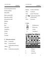
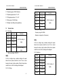
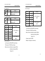
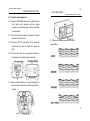
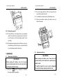
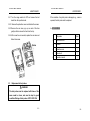
DIGITAL MULTIMETER DIGITAL MULTIMETER CONTENTS CONTENTS CONTENTS 4.9 Measurement of AC voltage ......18 1. SAFETY INFORMATION ......1 4.10 Diode test ......19 1.1 Preliminary ......1 4.11 Circuit continuity test ......20 1.2 Dos and don‘ts ......2 4.12 Resistance measurement ......21 1.3 Symbols ......3 4.13 Measurement of DC current ......22 1.4 Precautions ......4 4.14 Measurement of AC current ......23 2. DESCRIPTION ......5 4.15 Phone line mode detection ......24 2.1 Names of parts ......6 4.16 Judgment and tracking of cable line ......26 2.2 Switches, buttons and input jacks ......7 4.17 Network cable integrity test ......28 2.3 Display ......8 3. SPECIFICATIONS ......10 4.18 Non-contact voltage detection ......31 3.1 General ......10 4.19 Operating precautions of protective ......32 3.2 Technical index ......11 4. OPERATING INSTRUCTIONS ......14 4.1 Function switching ......14 4.2 Range switching 4.3 Maximum value measurement cover 4.20 Automatic power off ......33 5. MAINTENANCE ......33 ......15 5.1 Replacement of batteries ......33 ......15 5.2 Replacement of fuse ......34 Replacement of test probes ......35 ACCESSORIES ......36 4.4 Reading holding ......15 5.3 4.5 Backlight source ......16 6. 4.6 Use of the test key ......16 4.7 Preparation for measurement ......16 4.8 Measurement of DC voltage ......17 DIGITAL MULTIMETER DIGITAL MULTIMETER SAFETY INFORMATION 1. SAFETY INFORMATION SAFETY INFORMATION 1.1.2 When the meter is received, please check whether it has been damaged during transport. Warning BE EXTREMELY CAREFUL WHEN USING THE METER. 1.1.3 After being stored Improper use of this device can result in electric conditions, the shock or destruction of the meter. Take all normal confirmed for damage. and meter delivered should be under harsh checked and 1.1.4 The test probes must be kept in good condition. Check safety precautions and follow the safeguards suggested in this manual. whether the insulation of the test probes has been To exploit full functionality of the meter and ensure damaged and whether any wire has been exposed. safe operation, Protection provided by the instrument 1.1.5 Using the test probes supplied can ensure safety. If will be impaired if used in a manner not specified by required, they must be replaced with those of the same the manufacturer. model or class. The Auto Range Digital Multimeter (hereinafter referred to as ―the meter‖) complies with the safety requirements for 1.2 electronic measuring instruments in IEC-61010-1, falls into 1.2.1 Use the right input jack, function and range. pollution degree 2 and meets the over-voltage standard of 1.2.2 Do not take measurements beyond the protection limits CAT 600V. Dos and don’ts indicated in the specifications. Follow all safety and operation instructions to ensure safe use of the meter. 1.2.3 Do not touch the metal tips of the test probes when connecting the meter to the circuit to be measured. With proper use and care, the meter will give you years of 1.2.4 Keep your fingers behind the probe barriers when satisfactory service. taking a measurement with an effective voltage of 1.1 above 60V DC or 30V AC. Preliminary 1.1.1 To operate the meter, the user must observe the 1.2.5 Do not take any voltage measurement if the value between the measuring terminal and the ground following normal safety rules: exceeds 1000V. 1) General protection against electric shock; and 2) Protection of the meter against misuse -1– -2- DIGITAL MULTIMETER DIGITAL MULTIMETER SAFETY INFORMATION SAFETY INFORMATION 1.2.6 Select the highest range if the value to be measured in Dangerous voltage may be present. the manual range is unknown. Double insulation (protection class II) 1.2.7 Do not connect the meter to any voltage source while CAT III – over-voltage (installation) category III, pollution the meter is in the current, resistance, diode or degree 2 per IEC61010-1, referring to the level of impulse continuity test range. withstand voltage protection provided. 1.2.8 Disconnect the test probes from the circuit under test Compliance with European Union (EU) directives before turning the range selector to change functions. Ground 1.2.9 Be careful that high voltage pulses at the test point Fuse may damage the meter when measurements are being taken on the switching power circuit of a TV set. 1.2.10 Do not measure the resistance, diode or continuity of 1.4 Precautions 1.4.1 Do not adjust or repair the meter by attempting to live circuits. 1.2.11 Do not use the meter near explosive gases, steam or dirt. remove the rear case. Such operation should only be performed by a technician who fully understands the meter and the electric shock risk involved. 1.2.12 Stop using the meter if any abnormalities or faults are noticed. 1.4.2 Remove the test probes from the circuit under test before opening the battery cover of the meter. 1.2.13 Do not use the meter unless its rear case is securely fastened in its original position. 1.4.3 To avoid any electric shock caused by erroneous readings, replace the batteries immediately when the 1.2.14 Do not store or use the meter in areas exposed to direct sunlight, high temperatures or high humidity. ― ‖ symbol appears on the LCD. 1.4.4 To avoid fire hazards, the replacement fuse must meet the specified voltage and current ratings of F 10A/500V 1.3 Symbols and F200mA/1000V (quick acting). Important safety information; refer to the operation 1.4.5 Use wet cloth and mild detergent to clean the meter; manual. do not use abrasives or solvents. 1.4.6 Turn to OFF switch off the power when is not in use. -3- - -4- DIGITAL MULTIMETER DIGITAL MULTIMETER SAFETY INFORMATION 1.4.7 Remove the batteries to avoid damages to the meter if DESCRIPTION 2.1 Names of parts it will idle for a long time. 1.4.8 Using this appliance in an environment with a strong radiated radio-frequency electromagnetic field (approximately 3V/m ),may influence its measuring accuracy.The measuring resul can be strongly deviating from the actual value. 2. DESCRIPTION - The meter is a portable specialized measuring instrument with a large digital LCD, as well as a backlight source for easy reading. single-hand The operation range selector makes designed measurement for easy. Overload protection and low battery indication are provided. It is an ideal multi-functional instrument with scores of practical applications for professional, factory, school, amateur and home use. - The meter can be used to measure DC and AC voltages and currents, and resistances, test circuit continuity and diodes, detect phone line mode, judge break points in cable lines, track the routing of cable lines, and detect network cable integrity and non-contact voltage. - The meter is provided with both automatic/manual ranges. - The meter is provided with the automatic shutdown function. - The meter is provided with the reading hold function. - The meter is provided with the maximum measurement. - The meter is provided with low battery voltage indication. -5- -6- DIGITAL MULTIMETER DIGITAL MULTIMETER DESCRIPTION DESCRIPTION 1)Non-contact voltage detection indicator light 2)LCD (liquid crystal display) 3)Data hold (HOLD) 4)Maximum measurement (MAX) Backlight key For switching on/off the backlight TEST key For measurement 10A jack Input jack for 10A current range mA/μA/V/Ω/ For mA/μA current, voltage, resistance 5)Range switch button (RANGE) jack and diode measurement 6)Function switch button (FUNC) COM jack Common terminal 7)Backlight key 8)Test key 2.3 Display 9)Panel AC (alternating current) 10) Rotary selector DC (direct current) 11)mA/μA/V/Ω/ jack AUTO Auto range 12) COM jack Ω Ohms (Resistance) 13) 10A jack 14) Guard plate 2.2 Switches, buttons and input jacks HOLD key For reading holding MAX key For maximum measurement RANGE key FUNC key For switching between auto and manual ranges LCD diagram For switching among measuring functions -7- V Volts (Voltage) A Amperes (Current) -8- DIGITAL MULTIMETER DIGITAL MULTIMETER DESCRIPTION Hz Hertz (Frequency) μ, m, k, M Symbols of units: micro, milli, kilo and million Continuity buzzer Maximum measurement H Reading being held 3.1.5 Polarity indication: automatic; ‗---‗ for negative polarity. 3.1.6 Over-range indication: ‗0L‘ or ‗---0L‘. 3.1.7 Unit indication: function and energy unit indication. Phone pick-up The RING line is clamped by the red clip The TIP line is clamped by the red clip 3.1.10Detecting network cable integrity, judging open circuit, Cable pair 3-6 short circuit, miswiring, split pair and reverse Cable pair 4-5 connection of the network cable, and shield integrity, Cable pair 7-8 SHORT Short circuit REVERSED Reverse connection MISWIRE Miswiring SPLIT PAIRS Split pair phone line. the routing of the cable line. Cable pair 1-2 Open circuit 3.1.8 Judging the ringing, standby or pick-up mode of the 3.1.9 Judging any breakpoint in the cable line, and tracking Audio signal OPEN General 3.1.4 Maximum value display: 1999 digits. Phone ringing Cable shield 3.1 3.1.3 Display: LCD. Phone standby SHIELD SPECIFICATIONS 3.1.2 Overload protection is available for all ranges. Low battery ①—② ③—⑥ ④—⑤ ⑦—⑧ 3. 3.1.1 Auto range and manual range options are available. Diode measurement MAX SPECIFICATIONS and displaying abnormity symbols. 3.1.11 Non-contact voltage detection. 3.1.12Automatic power off time: 15 min 3.1.13Fuse specification: F10A/500V, F200mA/1000V (quick acting) 3.1.14Battery under-voltage indication: The LCD displays the ‖ -9- ‖ symbol. - 10 - DIGITAL MULTIMETER DIGITAL MULTIMETER SPECIFICATIONS SPECIFICATIONS 3.1.15Operating power: 6F22 9V batteries 3.1.16Operating temperature: 0℃~40℃ 3.1.17Storage temperature: -10℃~50℃ 3.1.18Dimensions: 195×92×55mm 3.1.19Weight: about 400g (including batteries) 3.2 Technical index Range Resolution 200mV 0.1mV 2V 1mV 20V 0.01V 200V 0.1V 750V 1V Accuracy (0.8% of reading + 5 digits) - Max. input voltage: 750V AC 3.2.1 DC Voltage Range Resolution 200mV 0.1mV - Frequency range: 40~400Hz Accuracy - Response: average (rms of sine wave) 2V 1mV (0.5% of reading + 5 20V 0.01V digits) 200V 0.1V 1000V 1V NOTE: At the low voltage range, unsteady readings will appear before the test probes contact the circuit. This is normal (0.8% of reading + 5 because the meter is highly sensitive. When the test probes contact the circuit, the true reading will be displayed. digits) - 3.2.3 Resistance Max. input voltage: 1000V DC NOTE: Range Resolution At the low voltage range, unsteady readings will appear Accuracy 200Ω 0.1Ω before the test probes contact the circuit. This is normal 2KΩ 0.001KΩ because the meter is highly sensitive. When the test probes 20KΩ 0.01KΩ (1.0% of reading + 5 200KΩ 0.1KΩ digits) 2MΩ 0.001MΩ 20MΩ 0.01MΩ contact the circuit, the true reading will be displayed. 3.2.2 AC Voltage - 11 - 12 - DIGITAL MULTIMETER DIGITAL MULTIMETER SPECIFICATIONS 3.2.4 Diode test Range 3.2.7 AC Current Resolution Function 1mV Displaying approximate forward voltage of diode 3.2.5 Short-circuit test Range Range Resolution Accuracy 200μA 0.1μA 2000μA 1μA (1.5% of reading + 5 0.01mA digits) Resolution Function 20mA 0.1Ω Giving an alarm if the resistance 200mA 0.1mA 2A 0.001A (3.0% of reading + 5 20A 0.01A digits) is less than 70Ω 3.2.6 DC Current Range Resolution 200μA 0.1μA 2000μA 1μA (1.2% of reading + 5 20mA 0.01mA digits) Accuracy - Overload protection: A, mA range: fuse 200mA/1000V (quick acting) 10A range: fuse 10A/500V (quick acting) - Max. input current: μA/mA jack (μA range): 2000uA μA/mA jack (mA range): 200mA 200mA 0.1mA 2A 0.001A (2.0% of reading + 5 0.01A digits) 20A SPECIFICATIONS 10A jack: 10A - Frequency range: 40~400Hz - Response: average (rms of sine wave) - Overload protection: μA, mA range: fuse 200mA/1000V (quick acting) 10A range: fuse 10A/500V (quick acting) - Max. input current: μA/mA jack (A range): 2000uA μA/mA jack (mA range): 200mA 10A jack: 10A - 13 - - 14 - DIGITAL MULTIMETER DIGITAL MULTIMETER OPERATING INSTRUCTIONS 4. OPERATING INSTRUCTIONS OPERATING INSTRUCTIONS 4.4 Reading holding 1) To hold the reading during measurement, press the 4.1 ―HOLD‖ key, and the displayed value on the LCD will be Function switching locked. 1)Press the "FUNC" key to switch between AC and DC 2) Press the ―HOLD‖ key again to release the reading measurement at the current and voltage ranges. holding mode. 2)Press the "FUNC" key to switch between the diode and 4.5 continuity ranges. Backlight source 1) If the environment is too dark for reading during 4.2 measurement, hold on to the " Range switching 1) When the meter is turned on, it is at the auto range for measuring current, voltage and resistance. 2) Hold on to the " The range will go one level up with each press and return 3) After the backlight source is turned on, if the " to the auto range. source will shut down automatically 15 seconds later. 4.6 Maximum value measurement Phone (phone line mode detection), Tone (judgment and tracking of cable line), NetCable (network cable integrity when the meter is measuring current and voltage. the measured maximum Use of the test key 1) Press "TEST" to start detection when the meter is at the 1) The maximum value measurement function can be used display " key is not held down for more than 2 seconds, the backlight to the lowest level when the highest level is reached. 3) Hold the ―RANGE‖ key for more than 2 seconds to return 2) To " key again for more than 2 seconds to turn off the backlight source. 2) Press the "RANGE" key to enter the manual range mode. 4.3 " key for more than 2 seconds to turn on the backlight source. value detection) range. during measurement, press the ―MAX‖ key, and the measured 2) After the detection, the detection result indicator will flash. Press the "TEST" key to stop flashing and get ready for maximum value will appear on the LCD. the next detection. 3) Press the ―MAX‖ key again to release the maximum value measurement function. 4.7 Preparation for measurement 1) Turn the range selector and turn on the power. If the - 15 - 16 - DIGITAL MULTIMETER DIGITAL MULTIMETER OPERATING INSTRUCTIONS battery voltage is low (about ≤7.2V), the LCD will display the " 2) The ― " symbol, when the batteries must be replaced. ‖ symbol beside the input line indicates that the input voltage or current should not exceed the indicated value. This is intended to protect the internal circuit from OPERATING INSTRUCTIONS measurement mode, and press the ―RANGE‖ key to select the auto or manual mode. 4.8.4 Connect the test probes to the voltage source or load in parallel for measurement. 4.8.5 Take a reading in the main display area of the LCD. damage. 3) Set the range selector to the desired measurement function and range. In the manual range mode, if the The polarity indication will show the polarity of the terminal connected by the red probe. scale of the measured value is unknown beforehand, the NOTE: highest range should be set. 4) Connect the common test wire and then the live test wire 1) At the low voltage range, unsteady readings will appear during connection. Remove the live test wire first during before the test probes contact the circuit. This is normal disconnection. because the meter is highly sensitive. When the test 4.8 probes contact the circuit, the true reading will be Measurement of DC voltage displayed. WARNING 2) In the manual range mode, if the LCD displays ―OL‖ or There is the risk of electric shock. ―-OL‖ only, it means the measurement has exceeded the Pay special attention to avoid electric shock when measuring high voltages. Do not input any voltage of over DC1000V, which may damage the internal circuit though a higher voltage may be displayed. range and a higher range should be selected. 3) In the manual range mode, if the scale of the measured value is unknown beforehand, the highest range should be set and then lowered down gradually. 4.8.1 Plug the black probe into the COM jack and the red probe into the V jack. 4.8.2 Set the range selector to the V range position. 4.8.3 Press the ―FUNC‖ key to switch to the DC - 17 - - 18 - DIGITAL MULTIMETER DIGITAL MULTIMETER OPERATING INSTRUCTIONS 4.9Measurement of AC voltage OPERATING INSTRUCTIONS it means the measurement has exceeded the range and a higher range should be selected. WARNING There is the risk of electric shock. Pay special attention to avoid electric shock when measuring high voltages. Do not input any voltage of over AC750V rms, which may damage the internal circuit though a higher voltage may be displayed. 3) In the manual range mode, if the scale of the measured value is unknown beforehand, the highest range should be set and then lowered down gradually. 4.10 Diode test 4.10.1 Plug the black probe into the COM jack and the red 4.9.1 Plug the black probe into the COM jack and the red probe into the V jack. the ―FUNC‖ jack. 4.10.2 Set the range selector to the 4.9.2 Set the range selector to the 4.9.3 Press probe into the key V range position. to switch to the AC measurement mode, and press the ―RANGE‖ key to select the auto or manual mode. 4.9.4 Connect the test probes to the voltage source or load 4.10.3 Press the "FUNC" key to switch to the range position. test mode. 4.10.4 Connect the red probe to the anode and the black probe to the cathode of the diode for testing. 4.10.5 Take a reading in the main display area of the LCD. in parallel for measurement. 4.9.5 Take a reading in the main display area of the LCD. NOTE: 1) The meter indicates the approximate forward voltage drop of the diode. NOTE: 1) At the low voltage range, unsteady readings will appear before the test probes contact the circuit. This is normal 2) If the test probes are reversed or open, the LCD will display ‗0L‘. because the meter is highly sensitive. When the test probes contact the circuit, the true reading will be displayed. 2) In the manual range mode, if the LCD displays ‗OL‘ only, - 19 - - 20 - DIGITAL MULTIMETER DIGITAL MULTIMETER OPERATING INSTRUCTIONS 4.11 Circuit continuity test OPERATING INSTRUCTIONS 4.12 Resistance measurement WARNING WARNING There is the risk of electric shock. There is the risk of electric shock. When measuring the continuity of a circuit, make When measuring the impedance of a circuit, make sure the power is disconnected and the capacitor on the circuit is fully discharged. sure the power is disconnected and the capacitor on the circuit is fully discharged. 4.12.1 Plug the black probe into the COM jack and the red 4.11.1 Plug the black probe into the COM jack and the red probe into the jack. probe into the jack. 4.12.2 Set the range selector to the range position. 4.11.2 Set the range selector to the range position. 4.11.3 Press the ―FUNC‖ key to switch to the 4.12.3 Press the ―RANGE‖ key to select the auto or manual circuit continuity test mode. range. 4.12.4 Connect the test probes to the resistor or circuit under test for measurement. 4.11.4 Connect the test probes to the circuit for 4.12.5 Take a reading in the main display area of the LCD. measurement. 4.11.5 If the resistance of the circuit under test is less than 70, the buzzer in the meter will beep. NOTE: 4.11.6 Read the resistance of the circuit in the main display area of the LCD. NOTE: If the test probes are open or the resistance of the circuit under test is over 200, ―0L‖ will be displayed on the LCD. - 21 - 1) In the manual range mode, if the LCD displays ‗OL‘ only, it means the measurement has exceeded the range and a higher range should be selected. 2) In case of open input, the LCD will display the ‗0L‘ over-range mode. 3) If the resistance to be measured is higher than 1MΩ, the meter may take a few seconds to get a steady reading. This is normal for high resistance reading. - 22 - DIGITAL MULTIMETER DIGITAL MULTIMETER OPERATING INSTRUCTIONS 4.13 Measurement of DC current OPERATING INSTRUCTIONS it means the measurement has exceeded the range and a higher range should be selected. WARNING There is the risk of electric shock. 2) In the manual range mode, if the scale of the measured Turn off the power of the circuit under test, and then connect the meter to the circuit in series for measurement. 4.13.1Plug the black probe into the COM jack. When the current to be measured is below 200mA, plug the red value is unknown beforehand, the highest range should be set. 3) ― ‖ means the maximum input current of the mA jack is 200mA and that of the 10A jack is 10A. At the 10A jack, excess current will blow the fuse. probe into the uA/mA jack; when the current to be measured is over 200mA but below 10A, plug the red 4.14 Measurement of AC current probe into the 10A jack. WARNING 4.13.2Set the range selector to the desired current range position. 4.13.3Press the ―FUNC‖ key to switch to the DC measurement mode, and press the ―RANGE‖ key to select the auto or manual mode. There is the risk of electric shock. Turn off the power of the circuit under test, and then connect the meter to the circuit in series for measurement. 4.14.1Plug the black probe into the COM jack. When the 4.13.4Connect the test probes to the circuit under test in series for measurement. 4.13.5Take a reading in the main display area of the LCD. The polarity indication will show the polarity of the terminal connected by the red probe. current to be measured is below 200mA, plug the red probe into the uA/mA jack; when the current to be measured is over 200mA but below 10A, plug the red probe into the 10A jack. 4.14.2Set the range selector to the desired current range position. 4.14.3Press NOTE: the ―FUNC‖ key to switch to the DC measurement mode, and press the ―RANGE‖ key to 1) In the manual range mode, if the LCD displays ‗OL‘ only, - 23 - select the auto or manual mode. - 24 - DIGITAL MULTIMETER DIGITAL MULTIMETER OPERATING INSTRUCTIONS 4.14.4 Connect the test probes to the circuit under test in OPERATING INSTRUCTIONS 4.15.3 The "Phone" symbol stops flashing and the detection series for measurement. result is displayed. If the detection result symbol 4.14.5Take a reading in the main display area of the LCD. flashes, the mode of the phone line is as follows: RED-TIP flashing NOTE: 1) In the manual range mode, if the LCD displays ‗OL‘ only, RED-RING flashing it means the measurement has exceeded the range and a higher range should be selected. flashing The phone line is in the ringing mode. flashing The phone line is in the standby mode. 2) In the manual range mode, if the scale of the measured value is unknown beforehand, the highest range should be set. 3) ― ‖ means the maximum input current of the mA jack is 200mA and that of the 10A jack is 10A. At the 10A jack, The TIP line is clamped by the red clip. The RING line is clamped by the red clip. flashing The phone line is in the pick-up mode. excess current will blow the fuse. 4.15 Phone line mode detection 4.15.1 Plug the attached detection line into the jack in front of the meter and turn the rotary selector to the Phone range. 4.15.2 Clamp the two wires of the phone line with the two clips of the connecting line or plug the modular plug into the phone socket. Press the "TEST" key, and the "Phone" symbol will flash and the phone line mode detection will begin. - 26- 25 - DIGITAL MULTIMETER DIGITAL MULTIMETER OPERATING INSTRUCTIONS OPERATING INSTRUCTIONS cable. If there is any break point on the cable, its position can be judged. NOTE: 1) There should be no AC or DC signal in the cable under test. 2) If the audio signal is badly received, the volume switch of the receiver can be adjusted. NOTE: If the RED-TIP symbol flashes, the standby and pick-up modes of the phone line cannot be judged. In this case, be sure to clamp the RING line with the red clip and the TIP line with the black clip. 4.16 Judgment and tracking of cable line 4.16.1 Plug the attached detection line into the jack in front of the meter and turn the rotary selector to the Tone range. 4.16.2 Connect the outgoing wire of the connecting line to the target cable pair or connect the red line to the target cable and the black line to the ground. 4.16.3 Press the "TEST" key, and the" " symbol will flash to transmit an audio signal. Bring the antenna of the receiver close to the target cable and hold down the Receive key to receive the audio signal transmitted, and then you can judge the routing and continuity of the - 28- 27 - DIGITAL MULTIMETER OPERATING INSTRUCTIONS - 29 - DIGITAL MULTIMETER OPERATING INSTRUCTIONS 4.17 Network cable integrity test 4.17.1 Regular T568A/T568B cables can be judged for open circuit, short circuit, miswiring, split pair, reverse connection and shield integrity, and any abnormality can be specified. 4.17.2 Insert both ends of the cable into the jacks in the front and lower part of the meter. 4.17.3 Press the "TEST" key for testing. If the abnormality remains after the test, the ―Abnormal‖ symbol will 4.17.6 Below is a detailed description of different abnormalities: flash. 4.17.4 The front jack box can be separated to detect any fixed cable as the remote terminal conveniently. 4.17.5Insert a slotted screwdriver or any other flat object into the notch and push up hard to remove the front cable interface. - 30 - DIGITAL MULTIMETER DIGITAL MULTIMETER OPERATING INSTRUCTIONS NOTE: OPERATING INSTRUCTIONS 4.19 Operating precautions of protective cover 1) If the cable under test has no shield, the shield symbol will flash to indicate open circuit, which is normal. WARNING There is the risk of electric shock. 4.18 Non-contact voltage detection After the protective cover is lost, the voltage and 4.18.1 Sockets and power cords can be detected for the current measurement function of the meter should presence of AC voltage. be disabled for fear of electric shock. 4.18.2 Bring the upper part of the meter close to a conductor. 4.19.1There is a protective cover at the tail of the meter. To When a voltage is detected, the meter will give a avoid the risk of electric shock, the cable interface must sound and provide visual indication. be protected by the protective cover when the cable detection function is not used. 4.19.2 The figure below shows how the protective cover is used when the cable detection function is used. Front detection area of the meter WARNING There is the risk of electric shock. A voltage may still be present even if there is no indication. Do not rely on the non-contact voltage detection function to judge whether a voltage is present on a shielded wire. The detection operation may be affected by such factors as socket design, insulation thickness and type of wires. 4.19.3 The figure below shows how the protective cover is used when the cable detection function is not used. - 31 - - 32 - DIGITAL MULTIMETER DIGITAL MULTIMETER MAINTENANCE MAINTENANCE 5.1.2 Turn the range selector to OFF and remove the test wires from the input terminals. 5.1.3 Unfasten the screws and remove the battery cover. 5.1.4 Mount new batteries, replace the battery cover and fasten the screws. 4.20 Automatic power off 4.20.1 If the FUNC key or the range selector is not operated within 15 minutes during measurement, the meter will be shut down and enter the sleeping mode to save electricity. 4.20.2 To disable the automatic power off function, hold on to the HOLD key to start up the meter or press the HOLD key in the sleeping mode to wake it up. 5.2 5. MAINTENANCE 5.1 Replacement of fuse WARNING Replacement of batteries Before opening the battery cover, remove the test WARNING Before opening the battery cover of the meter, remove the test probes from the circuit under test to electric shock. To avoid fire hazards, be sure to use the designated avoid the risk of electric shock. 5.1.1 When the ― probes from the circuit under test to avoid the risk of ‖ symbol is displayed, the batteries fuse (at rated voltage, amperage and blow rate). should be replaced immediately. - 33 - - 34 - DIGITAL MULTIMETER DIGITAL MULTIMETER MAINTENANCE 5.2.1 Turn the range selector to OFF and remove the test leads from the input terminals. ACCESSORIES If the insulation of any test probe is damaged, e.g., a wire is exposed, the test probe must be replaced. 5.2.2 Remove the protective cover and unfasten the screws. 5.2.3 Remove the rear case, pry up one end of the fuse 6. ACCESSORIES gently and then remove the fuse from the clip. 5.2.4 After a new fuse is mounted, replace the rear case and fasten the screws. 5.3 1) Test probes 1 pair 2) Test connect line 1 3) Receiver 1 4) Protective cover 1 5) Remote unit 1 6) Operation manual 1 Replacement of test probes WARNING The test probes must be replaced with those of the same model or class, and must be kept in good condition. Ratings of test probes: CAT III 600V 10A. - 35 - - 36 -