1
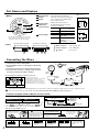
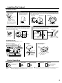
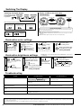
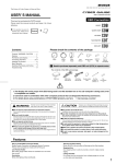
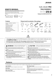
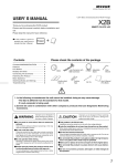
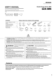
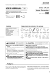
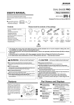
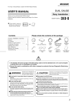
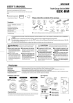
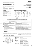
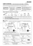
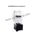
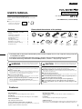
(DPT-H As of July, 2015 No.1)
USER’S MANUAL
Easy Installation
RPM / MOTOR RPM+ DIGITAL
Thank you for purchasing this PIVOT product.
Please read this manual carefully and keep it for future
reference.
● If this produc t is given to
another user, make sure to
include this User’s Manual.
Product
DPT-H
For HYBRID Cars (TOYOTA/HONDA)
+
Contents
Please check the contents of the package
Contents / WARNING / CAUTION ………
Features ……………………………………
Part Names and Displays ………………
Connecting The Wires ……………………
Installing The Product ……………………
Basic Operation ……………………………
Switching The Display ……………………
Illumination color settings ………………
Illumination brightness settings…………
Troubleshooting ……………………………
1
1
2
2
3
3
4
4
4
4
Meter
Screw
Unit
Nut
Gauge Cable
Allen
Wrench
OBD Cable
with Fuse 3A
Double-sided
Tape
Cushion
Tape
IGN Cable
with Fuse 3A
Cut
Connectors
×2
Meter Holder
Zip Ties
(Large) × 2
(Small) × 5
A-Pillar
Stand
User’s
Manual
(This Book)
1. The display will not be proper if the ECU being used is not the standard one or if a sub-computer is being used, even
in compatible car models.
2. Cannot be used in combination with other company’s products that use Diagnostic Monitoring Connectors.
3. For details about using combinations of PIVOT OBD2 products, see here. ⇒ http://pivotjp.com/obd/
WARNING
Improper use or disregard of these warnings
may result in the injury or death of people.
●Do not work in areas where there is excessive exhaust.
Due to vehicle exhaust emission poisoning or fire may result in a damage to
humans.
●Do not crush the cable.
Please be careful that the cable does not get crushed by the seat rail or car
door steel plate, nor cut by any sharp steel plate as this may cause a poor
connection or an electric short leading to fire or other danger.
●Do not operate while driving.
Operating or checking the display during driving may cause an accident;
please use with the utmost consideration for safety.
●Please securely fasten the product to a stable place and be
sure to store bundle away all wires with tape, etc...
It is very dangerous to pull tangled wires by force or allow tangled wires to
interfere with driving.
CAUTION
Improper use or disregard of these warnings may cause
injury to persons, damage the product and other things.
●This product is for DC12V cars;
Installation cannot be carried out on cars with other voltage batteries.
●Just after installation do not exert any strong force on the product.
When double-sided tape is used for an installation be warned that when hot the tape
temporarily losses adhesiveness.
●Do Not Use Chemical Cleansers.
If the unit gets dirty please wipe with a soft cloth to remove any dirt. Do not use chemical
cleansers such as thinner, benzene, or alcohol.
●Do not install the product in any place subject to high temperature or
any place where water may be splashed.
●Make sure to replace all screws and parts to their original place.
●Do not install the product in a place where it will cause distraction.
●Do not, in any manner, process, take apart, or make changes to this
product.
Features
The world's first meter designed for hybrid cars for easy viewing of both engine and motor rpm. (Patent pending)
Easy Installation
Meter Holder included
Simple coupler connection to Diagnostic monitor connector.
The included full cover type holder allows seamless installation to a
number of places.
Dual Display
Boost is shown by the needle, water and voltage are shown digitally.
Black Titanium Bezel
Peak Hold
Save and display each peak reading after engine starts.
High quality black titanium bezel.
Additional Sensor
2-Color Illumination Switch with 3-step Dimmer
If the use of a sub computer makes getting correct readings impossible or if
data cannot be received via OBD, we offer additional separately sold sensors.
Illumination switc h allows sele c tion bet ween t wo c olor s and
brightness adjusted with three-step dimmer.
1
Part Names and Displays
[ Meter ]
1
1 Analog Display
Display RPM and Motor RPM data.※
2 Needle
Shows the current values and peak value.
3 Switch
Use to change modes of digital display
and reset the peak value.
4 Digital Display
Display switches between types.
5 Illumination
Normally illuminated when on display
and Three-step dimming.
(night illumination)
3
2
6 Display Range
ø60
ø65
Unit
70
Digital Display
Red
Analog Display
RPM [ 0 〜 8000rpm]
Motor RPM [0 〜 9000rpm]
Digital Display
Water Temp [ - 35 〜 150 °C ]
Voltage [ 8 〜 18 V ]
Motor RPM [0 〜 32000rpm]
※ Not
(View from Gauge Connection)
15 30
(Switchable)
display Motor RPM on Analog Display
when the Meter displays RPM by needle. See
the Digital Display to check the Motor RPM.
[Unit:mm]
Meter
Dial & Needle : White or Blue
Analog Display
4
[ Unit ]
Size
50
Depth22
(View from Car Connection)
7
8
7 Meter connector
Connect gauge cable
8 Power connector
Connect OBD cable
9
No need to use
10 Spare
9 10
Connecting The Wires
① Turn the power switch to Ready Mode.
② Insert the OBD Connector to the Diagnostic Monitoring
①
Connector.
③ Insert the 4-pin Connector to the backside of the meter.
④ Insert the 5-pin Connector of Gauge Cable and 6-pin
Connector from the Power Cable to the Unit.
4-pin
Connector
③
③
①
⑤
TOYOTA ① ② ③ ④ ⑦
②
Meter
Holder
①By the accelerator pedal
②At the right foot of the driver seat (with lid)
③At foot of driver seat in the center
④At the left foot of the driver seat (with lid)
⑤At the right side of the center console
⑦Behind the panel by the steering (with lid)
⑦
②
Ready
Mode
Diagnostic
Monitoring
Connector
Placement Diagram for Diagnostic Monitoring Connector
④
POWER
Backside
of the
meter
④
(1.5 m)
Unit
(0.5 m)
6-pin
Connector
5-pin
Connector
HONDA ② ④ ⑤
④
If the meter not activate from individual differences in car models or some reasons after the engine starts, you need to change the power
source and connect the power cable to IGN. ⇒See【If connect the power cable to IGN (Not normally required)】below.
If connect the power cable to IGN (Not normally required)
The meter start-up and stop is differ in power connection method.
Normal (not using IGN Cable)
Linked to the power switch
Linked to the ECU
Diagnostic
Monitoring
Connector
OBD Cable
IGN (using IGN Cable)
Red
Unplug the connector of Yellow and Red cable of OBD Cable and
connect Yellow cable of IGN Cable into the connector on Yellow cable,
then connect to IGN cable to IGN of car. (Do not connect to Acc)
Yellow
=Cut Connector
IGN
Yellow
IGN Cable
(12V with Key ON)
Notes about using the OBD Connector
Make sure to grip the
distended portions when
pulling it out or inserting it.
CAUTION
D o n o t p u ll o n t h e w i r e s
when trying to remove the
connector; the wires may
become disconnected.
If you unable to get a grip
on the distended portions.
W i t h s o m e c ar m o d e l s i t
m ay b e d i f f i c u l t t o g e t a
good grip on the connector.
In such case, pull
out the connector
by p u l l i n g o n t h e
end of the zip tie.
How to use the Cut Connectors
1
10 mm
Peel of f of the vinyl
cover at connection.
2
2
10 mm
Peel off of the vinyl cover at
the end of the product’ s wire.
4
3
Wrap around both
wire coils.
5
Close tightly with
cut connector.
Insulate with vinyl
tape.
When crimping, please
use crimpers or use pliers
to bend and then solder
together.
Installing The Product
Installing The Meter
A Installation with the Meter Holder
① Fa s t e n u s i n g t h e
double-sided tape.
② After deciding the position
and angle of the meter face,
fasten the Hexagonal bolt
on both sides to secure.
③ Affix the Cushion Tape to the base of the meter, connect the Gauge Cable to the
Meter, and install the Meter into the Meter Holder. Please add the Cushion Tape
if the Meter not fixed.
Cushion Tape
Meter Holder
Cushion Tape
Double-sided
tape
Clean
to remove
oil and dust
Back side
of Meter
Note : Please be sure about
where you wish to install the
meter, as it is not advisable to
reuse double-sided tape.
Cushion Tape
Hexagonal bolt
Gauge Cable
B Installation to panel or something
Connector
C Installation to A-pillar using A-pillar Stand
Cut the Cushion Tape in half, affix to base of the Meter to be on press
fit condition with adjusting number. And connect the Gauge Cable to
the Meter and insert into the panel.
Make a ø5 hole on the place to install the meter of the A-pillar, and fix the
Meter using A-pillar Stand with Screw and Nut.
A-pillar
Cushion Tape
A-pillar
Panel
Screw
Nut
Gauge
Cable
Cut the Cushion
Tape in half
A-pillar
Stand
Cushion Tape
ø5 Hole
Installing The Unit
As shown in the below diagram , fasten the unit into
positions not usually affected by water.
Fastening
to Flat Space
(Example of Installation)
Under the steering
column cover
On the back side
of the under cover
When Fastenings to
a Cable or Pipe
Unit
Zip tie
(Large)
On the inside of
the driver’s door
Double-sided
tape
Through
holes
Thick cable
or pipe
Clean to
remove
oil and dust.
Do not install into low positions
Basic Operation
1
Ready Mode
POWER
Turn the power switch
to Ready mode.
2
Opening Demo
3
Display Each Mode
Opening ●When in Ready Mode the needle will move to the extreme left several
times for searching position. Then it will move to the maximum value
Demo
4
Engine Stop
5
Meter OFF
The needle stops
in the vicinity of
lowest value.
●Due to analyzation time for the car data transmission it may take up to a few
seconds from engine start before opening demo. (except wiring IGN)
and finally to reading for current measurement item.
3
Switching The Display
Display and Reset the Peak Value
Switching The Digital Display
Press switch to change
the multi-digital display
in operation
Water Temp
Voltage
Real-time Display
Motor RPM
Peak Value Display
for 3 Seconds
for 3 Seconds
Press
Switch
Press
Switch
Water Temperature Reading the Display
0 〜 99 °C
100 〜150 °C
The third place from the
left shows “ ” (Celsius).
Numerical Value Only.
- 35 〜 -1 °C
The first place on the
left shows “ ” (minus).
-
c
(Lighting)
With no operation
5 Seconds
(Blinking)
Reset the Peak Value
Only the peak value on display will be reset. This will return to the Real-time Display
for the currently displayed mode.
Motor RPM Reading the Display (display unit : 100rpm)
0 〜9900rpm
over 10000rpm
● Peak readings are reset when the power is turned OFF.
● For RPM and Water Temperature the high will be shown and for Voltage the low will be
(decimal point
is lightning)
displayed.
● For Motor RPM the high Peak Value will be shown on the Digital Display.
Illumination color settings
1
+
POWER
2
3
Display the current
illumination color setting
READY Mode
(Initial value)
After the meter off,
Engine start during
pressing the switch
Release the switch
after displayed
the current setting
5
[ c-1 = White,
Press
the switch
for 6 seconds
2
Display a peak value after
3 seconds and the current
brightness after 6 seconds
Holding downs the switch
in operation
c-2 = Blue ]
Release the switch
after setting is done
Back to normal display with
no operation for 5 seconds
Setting Completed
Each pressing will change the color
Adjustment in case of anxious about reflected illumination of door mirror
or something
Illumination brightness settings
1
4
Press the
switch to change
the color
3
(Initial value)
4
Press the switch
to change the brightness
Release the switch
after displayed
the current setting
(High)
5
Release
the switch
after setting is done
6
Back to normal display with
no operation for 5 seconds
(Mid)
(Low)
Each pressing will change the brightness
Setting Completed
Troubleshooting
Trouble
Does not work with Engine start.
Possible Causes
Possible Solutions
Poor connection of Gauge cable ,
6-pin Connector or OBD Connector wires.
Please reconfirm whether wiring and connections
are correct or not.
The unit has been installed into an incompatible
car model.
Please reconfirm the Fitting List.
Upon starting up, the unit will not start in the
newly changed display.
Because after changing displays, if the car’ s engine is turned off within 3 seconds, the new setting will
not be stored, make sure to wait at least 3 seconds before turning the engine off.
Before the opening demo starts the needle briefly
moves.
This is due to a special characteristic of the meter and is not a malfunction.
The displayed values are different from the standard
meter.
Due to the ECU information received, the displayed values on this product may differ from those of
standard or other meters.
※Our products have already been recognized as our Industrial Property or are in the process of receiving Industrial Property status.
※We plan in the near future to take all possible legal measures to protect against unfair competition from look-alike products using similar designs, regulating characteristics,
circuitry and circuitry layout.
※We strictly prohibit the unlicensed use of the PIVOT trademark and the unauthorized use of PIVOT User’s Manual.
4
PIVOT CORPORATION 87-3, Shimookada Okada, Matsumoto-shi, Nagano, 390-0313 JAPAN