1
DP8xxx
with
Dual Ethernet Ports
for
Density Series
Systems
USER’S GUIDE
Cubix Corporate Headquarters ● 2800 Lockheed Way, Carson City, Nevada 89706-0719
Tel (775) 888-1000 ● Fax (775) 888-1001 ● Customer Service (800) 829-0550
European Headquarters ● One Hunter Road, Kirkton South, Livingston, EH54 9DH, Scotland
Tel 01506 465065 ● Fax 01506 465430
International + 44 1506 465065 ● Customer Service 0800 591 887
Cubix Web Site: http://www.cubix.com
NOTICE
Cubix Corporation reserves the right to revise this documentation and to change content from
time to time without obligation on the part of Cubix Corporation to provide notification of such
revision or change. Additionally, Cubix Corporation assumes no responsibility for its use and
provides this documentation without warranty of any kind, either implied or expressed. Cubix
Corporation may make improvements or changes in the product(s) and/or program(s) described
in this documentation at any time.
All product names mentioned in this document are trademarks or registered trademarks of their
respective owners.
Mention of third-party products is for informational purposes only and is not to be considered an
endorsement or recommendation. Cubix Corporation assumes no responsibility for the
performance of these products.
Copyright © 1999 by Cubix Corporation
All Rights Reserved
Printed in U.S.A.
Doc. #0879
DP8xxx With Dual Ethernet Ports
User’s Guide
Table of Contents
Chapter 1 - Introduction
Introduction . . . . . . . . . . . . . . . . . . . . . . . . . . . . . . . . . . . . . . . . . . . . . . . . . . . . . . . . . . .1
Overview of the DP8xxx Board . . . . . . . . . . . . . . . . . . . . . . . . . . . . . . . . . . . . . . . . . . . .2
Chapter 2 -Jumper Settings and Memory Installation
Jumper Settings . . . . . . . . . . . . . . . . . . . . . . . . . . . . . . . . . . . . . . . . . . . . . . . . . . . . . .3-5
Chapter 3 - Board Installation
Warnings and Procedures . . . . . . . . . . . . . . . . . . . . . . . . . . . . . . . . . . . . . . . . . . . . . . . .6
Board Installation . . . . . . . . . . . . . . . . . . . . . . . . . . . . . . . . . . . . . . . . . . . . . . . . . . . . . . .7
Chapter 4 - DP8xxx Board Information and Technical Specifications
Termination Card for Processor Slot 1 . . . . . . . . . . . . . . . . . . . . . . . . . . . . . . . . . . . . . . .8
Ethernet Adapters LEDs . . . . . . . . . . . . . . . . . . . . . . . . . . . . . . . . . . . . . . . . . . . . . . . . . .8
Other LEDs . . . . . . . . . . . . . . . . . . . . . . . . . . . . . . . . . . . . . . . . . . . . . . . . . . . . . . . . .8-9
Memory Configuration and Management . . . . . . . . . . . . . . . . . . . . . . . . . . . . . . . . . . . . .9
System Interrupts . . . . . . . . . . . . . . . . . . . . . . . . . . . . . . . . . . . . . . . . . . . . . . . . . . . . . .10
Technical Specifications . . . . . . . . . . . . . . . . . . . . . . . . . . . . . . . . . . . . . . . . . . . . . . . . .11
Appendix A-Customer Service Information . . . . . . . . . . . . . . . . . . . . . . . . . . . . . .12
List of Figures
Figure 1 Density Series System . . . . . . . . . . . . . . . . . . . . . . . . . . . . . . . . . . . . . . . . . .1
Figure 2 DP8xxx Series Board Layout . . . . . . . . . . . . . . . . . . . . . . . . . . . . . . . . . . . . . . .2
Figure 3 Inserting Server Board Into Chassis Group . . . . . . . . . . . . . . . . . . . . . . . . . . . .7
Figure 4 DP8xxx End Bracket . . . . . . . . . . . . . . . . . . . . . . . . . . . . . . . . . . . . . . . . . . . . .8
List of Tables
Table 1 SCSI Jumper Settings for SJP2 . . . . . . . . . . . . . . . . . . . . . . . . . . . . . . . . . . . . .3
Table 2 Ethernet Jumper Settings for JP1 and JP2 . . . . . . . . . . . . . . . . . . . . . . . . . . . . .4
Table 3 VGA Jumper Settings for JP3 . . . . . . . . . . . . . . . . . . . . . . . . . . . . . . . . . . . . . . .4
Table 4 RAID Jumper Settings for JP4 . . . . . . . . . . . . . . . . . . . . . . . . . . . . . . . . . . . . . .5
Table 5 Memory Map . . . . . . . . . . . . . . . . . . . . . . . . . . . . . . . . . . . . . . . . . . . . . . . . . . .9
Table 6 I/O Map . . . . . . . . . . . . . . . . . . . . . . . . . . . . . . . . . . . . . . . . . . . . . . . . . . . . . . .9
Table 7 System Interrupts . . . . . . . . . . . . . . . . . . . . . . . . . . . . . . . . . . . . . . . . . . . . . . .10
Table 8 Density DP8xxx - Technical Specifications . . . . . . . . . . . . . . . . . . . . . . . . . . . . .11
Chapter 1—Introduction
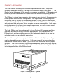
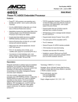
The Cubix Density Series system houses multiple server-class Intel‚ compatible
computers neatly and efficiently in a single rack-mountable drawer (see Figure 1). The
Density Series is designed for the purpose of computer consolidation. Cubix equipment
solves the problems associated with space-contrained backroom computing centers.
The DP8xxx is a single board computer which supports two Pentium III processors in
a dual symetric multiprocessor configuration. This single board computer plugs into
backplanes that are divided into independent groups. ("Group" refers to a segmented
number of slots within the backplane that will accommodate a Density processor board
and peripheral third party cards, which comprise the server-class system.) Under operating systems that can support multi-threaded applications, the Cubix DP8xxx board
executes these applications with increased speed.
The Cubix DP8xxx can be purchased with just one Pentium III processor and later
upgraded, as the need for more processor power arises. This board also has two
Ethernet ports, which provide the customer with high-speed data links to be used in a
redundant mode or as a method of segmenting.
There are three steps to insure proper installation of this board. (1) Jumper settings
must be checked for proper configuration. (2) A power down of the group where the
board will be installed must be done. (3) The board must be inserted into the proper
group slot. This Quick Reference Guide provides details on switch and jumper settings,
the steps necessary for proper installation of the board and information regarding the
technical specifications of the DP8xxx board.
Figure 1 Density Series System
1
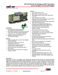
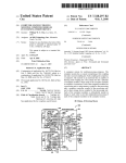
OVERVIEW OF THE DP8xxx BOARD
This processor board uses the Intel 440GX chipset and two Pentium III processors
with current speeds up to 6000Mhz. As new processors become available, Cubix
upgrades their technology providing for the customer the latest in server consolidation.
The DP8xxx board has four DIMM sockets for a maximum of 2GB of memory. The
DP8xxx board uses a 100MHz front side bus and 33MHz-PCI bus timing. This board is
designed for the Density Series chassis which can hold up to four DP8xxx boards.
Figure 2 shows the DP8xxx board layout.
Once installed in a Cubix Density System, each DP Series board becomes an
independent computer. The system multiplexor allows all Density System computers in
a chassis to share a single floppy disk drive and CD-ROM drive. The monitor, mouse
and keyboard may be shared between multiple chassis (up to 8).
The DP Series computers include on-board video, two serial ports, one parallel port,
keyboard and mouse support, memory support and floppy drive support. Also included
are two integrated Ethernet controllers with two RJ-45 connectors for 10/100 Base-TX
operation. The DP8xxx has a Wide Ultra2 SCSI which supports up to three low voltage
differential (LVD) SCSI hard disk drives. This board supports PCI expansion slots only.
Figure 2 DP8xxx Series Board Layout
2
Chapter 2—Jumper Settings and Memory Installation
JUMPER SETTINGS
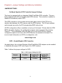
On-Board Symbios SCSI Controller/Jumper Settings
The board is equipped with an integrated Ultra2 Fast/Wide SCSI controller. This controller supports both LVD and single-ended SCSI devices. The controller is enabled or
disabled via hardware jumper SJP2.
The SCSI controller is a bus master device which gains control of the PCI bus to
transfer data between the CPU memory and the SCSI devices. The I/0 base address
and interrupts are set by the PCI plug and play BIOS at boot time.
A SCSI configuration utility is available on boot-up of the board. Shortly after the SCSI
BIOS information displays, the configuration program can be accessed by pressing
Control-C. The configuration utility will allow you to scan the SCSI bus, change
configuration options, and view a list of SCSI devices connected to the board. For
more in depth information on SCSI re-configuration, visit:
www.lsilogic.com
SJP2 – Enable/Disable SCSI Controller
As stated above, the on-board Symbios Ultra2 Fast/Wide SCSI adapter can be enabled
or disabled with jumper SJP2 (see Figure 2 for SJP2 location).
Table 1 defines the jumper settings for SJP2.
Table 1 SCSI Jumper Settings for SJP2
Jumper
SJP2
Function
Jumper On
Pins 1-2
Enabled
SCSI
3
Jumper On
Pins 2-3
Disabled
JP1 and JP2 - On-Board Ethernet Controllers/Jumper Settings
The board is equipped with two integrated Intel 82559 Ethernet controllers that have
two RJ-45 10/100 BASE-TX connectors on the mounting bracket at the rear of the
board. The I/O addresses and interrupts are set by the PCI plug and play BIOS at boot
time. These controllers are enabled or disabled via hardware jumpers JP1 and JP2
(see Figure 2 for jumper locations). JP1 corresponds to the Ethernet controller and
Ethernet port farthest from the processors. JP2 corresponds to the Ethernet controller
and Ethernet port closest to the processors. For unique situations requiring the disabling of the Ethernet controllers, JP1 and JP2 are incorporated onto the DP8xxx board
Table 2 defines the jumper settings for JP1 and JP2.
Table 2 Ethernet Jumper Settings for JP1 and JP2
Jumper
JP1
JP2
Function
Ethernet Controller
Ethernet Controller
Jumper On
Pins 1-2
Enabled
Enabled
Jumper On
Pins 2-3
Disabled
Disabled
JP3 - On-Board Video Graphics Controller/Jumper Settings
The board is equipped with an on-board video graphics controller. This controller is
enabled or disabled via a hardware jumper JP3 (see Figure 2 for JP3 location). For
special applications that may require disabling of the VGA controller, JP3 has been
incorporated onto the Cubix DP8xxx board.
Table 3 defines the jumper settings for JP3.
Table 3 VGA Jumper Settings for JP3
Jumper
JP3
Function
Jumper On
Pins 1-2
Enabled
VGA
Jumper On
Pins 2-3
Disabled
JP4 - RAID Interrupt
The DP8xxx comes from the factory with JP4 in a “normal” setting, unless otherwise
specified (a “normal” setting has the jumper on pins 1 and 2). If an AMI RAID card
using the internal hard drives needs to be installed at a later time, the jumper will have
to be removed, and placed on pins 2 and 3.
4
Table 4 Jumper Settings for JP4
Jumper
Function
JP4
Normal
Jumper On
Pins 1-2
Jumper On
Pins 2-3
Enabled
RAID
Enabled
JP5 – Flash BIOS
If the Flash Bios is to be upgraded, a shunt must be installed on the 2-pin jumper JP5
(see figure 2 for JP5 location). Upgrades typically come on a floppy disk and are
accompanied by upgrade instructions.* When the upgrade is complete, the shunt
should be removed to protect the system from accidental erasure.
*Cubix provides Flash Bios upgrades via the Cubix web site. The web site address is
provided in Appendix A of this manual.
Other Jumper Settings
Jumpers JP6, 7, 8, and 9 (CPU speed) are processor dependent and should not be
changed from factory settings. J2 is a reset jumper incorporated on the board
specifically for testing by Cubix Corporation.
DIMM MEMORY INSTALLATION
Additional memory can be installed on DP8xxx board. There are four DIMM slots
available on this board (see Figure 2 for DIMM slot location). If only one DIMM is
installed, this DIMM should be installed in the DIMM slot farthest away from the
processor. Each additional DIMM should be added in the adjacent slot. The sequence
of DIMM installation relative to DIMM size is not important.
For installation, the card interface tabs must be aligned. Firmly seat the DIMM(s) into
place.
Please note the following information regarding DIMMs.
●
●
●
●
DIMMs must be 168 pin, 3.3 volt 100MHz (PC100) ECC SDRAM (72 bits).
DIMMs do not need to be installed in pairs, and different sizes may be mixed.
DIMMs may be either registered or unbuffered. Registered and unbuffered
DIMMs may NOT be mixed.
DIMMs must have gold contacts (edge connectors).
5
Chapter 3—Board Installation
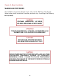
WARNINGS AND PROCEDURES
The installation of processor boards require entry into the CPU bay of the Density
Series system which is restricted to service personnel only. Accordingly, the following
warnings apply.
CAUTION!
CONTAINS HAZARDOUS VOLTAGES,
NO USER SERVICEABLE PARTS INSIDE
ATTENTION!
TENSION DANGEREUSE, L’APPAREIL NE COMPORTE AUUN
ELEMENT QUE L’UTILISATEUR PULSSE REPARER
ACHTUNG!
GEFAHRLICHE STROMSPANNUNGEN!
KEIN BENUTZER ZUGANGLICHE TEILE!
CAUTION!
GROUP POWER MUST BE OFF BEFORE INSTALLING ANY CUBIX
PROCESSORS, PERIPHERAL BOARDS, OR THIRD-PARTY
PERIPHERAL CARDS. FAILURE TO FOLLOW THIS WARNING
MAY RESULT IN DAMAGE TO THE DENSITY SERIES SYSTEM AND
BOARDS BEING INSTALLED.
6
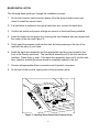
BOARD INSTALLATION
The following steps guide you through the installation process.
1. At the front console, select and turn power off to the group location where you
intend to install the server board.
2. If a hard-drive is installed in the group hard drive slot, remove the hard drive.
3. Confirm the switch and jumper settings are correct on the board being installed.
4. Insert the board into the group slot, ensuring the card interface tabs are aligned with
the center of the slot (see Figure 3).
5. Firmly seat the processor card into the slots by firmly pressing on the top of the
card with the palm of your hand.
6. Install the hard drive assembly into the appropriate hard drive bay located in the
front of the Density enclosure. The hard drive assembly will fit into the hard drive
interface. Press firmly to seat. If the hard drive assembly does not fit into the interface, check to see that the server board is completely seated in the slot.
7. Connect all appropriate ribbon connectors and L-bracket connectors.
8. At the front of the console, apply power to the processor group.
Figure 3 Inserting Server Board into Chassis Group
7
Chapter 4—DP8xxx Board Information and Technical Specifications
TERMINATION CARD FOR PROCESSOR SLOT 1
When only one processor is in place, a termination card is necessary in the other slot.
If for any reason a processor is removed, the Group where in the board is located
must be powered down. The processor can then be removed, and replaced with a
termination card before the DP8xxx is powered up.
ETHERNET ADAPTER LEDs
Upper
LED’s
In each of the RJ-45 connectors and visible in the mounting bracket are
two sets of light emitting diodes (LEDs). Figure 4 displays the DP8xxx
end bracket.
Lower
LED’s
On the Upper set:
●
●
The top LED will emit green when the interface has a valid
connection to an Ethernet hub, and blinks when there is activity.
The bottom LED emits green when the interface is set to 100 Mbit/s.
On the Lower set:
●
●
The top LED will emit green when the interface has a valid
connection to an Ethernet hub, and blinks when there is activity.
The bottom LED emits green when the interface is set to 100 Mbit/s.
Figure 4
DP8xxx End
Bracket
OTHER LEDs
SCSI Activity LED
There is an LED located on the top edge of the DP8xxx board next to the internal SCSI
connector (SJ2, see Figure 2 for location). The LED will be red when the SCSI drive is
busy. This LED is only visible when the cover is off of the Density System.
8
DP8xxx Board Power LED
There is a Board Power LED light located on the DP7xxx board between the COM 2
connector (J5) and the fan connector (J13, see Figure 2 for location). This LED light
will be green when there is power to the board. This LED is only visible when the cover
is off of the Density System.
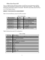
MEMORY CONFIGURATION & MANAGEMENT
Table 5 shows the Memory map for the DP processor.
Table 5 Memory Map
Memory Range
00000-9FFFF
A0000-AFFFF
B0000-B7FFF
B8000-BFFFF
C0000-C7FFF
C8000-DFFFF
E0000-FFFFF
Size
640KB
64KB
32KB
32KB
32KB
96KB
128KB
Use
Conventional Memory
VGA Graphics Buffer
MDA Text Buffer
VGA/CGA Text Buffer
VGA Bios
Available
System & PCI BIOS
Table 6 defines the board’s I/O configuration.
Table 6 I/O Map
ISA Ports
0000-00FF
Description
Various "AT" functions in ISP chip and keyboard controller
01F0-01F7
02F8-02FF
03A0
03A8-03AF
03B4-03B5
0378-037F
03C0-03CF
03D4-03D5
03F0-03F7
03F8-03FF
IDE hard drive interface
COM2
Cubix supervisory interface
IES serial port
VGA
LPT1
VGA
VGA
Floppy / IDE
COM1
9
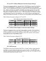
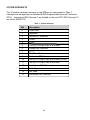
SYSTEM INTERRUPTS
The 16 system hardware interrupts on the DP8xxx are represented in Table 7.
Interrupts are managed by two standard 8259A Programmable Interrupt Controllers
(PICs). Interrupts at IRQ 0 through 7 are located on the main PIC; IRQ 8 through 15
are on the SLAVE PIC.
Table 7 System Interrupts
IRQ
Description
0
Timer clock
1
Keyboard
2
3
4
5
6
7
8
9
10
11
12
13
14
15
Second PIC controller
COM2
COM1
Set By PCI Plug & Play at boot time
Floppy Disk Controller
LPT1
Real Time Clock
Redirected IRQ 2
Set By PCI Plug & Play at boot time (or IES)
Set By PCI Plug & Play at boot time
Available (or PS/2 Mouse)
Math Coprocessor
Not Used
Secondary IDE Controller
10
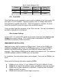
TECHNICAL SPECIFICATIONS
Table 8 represents the technical specifications for the Density DP8xxx board.
Table 8 Density DP8xxx - Technical Specifications
CPU-Central Processing Unit
L2 Cache
System Chip Set
System Memory
Speed
Width
Max Size
Type
Peripheral Bus Support
System BIOS
Super I/O
Serial/Assignment
UART Type
Parallel/Assignment
Dual On-Board LAN Interfaces
VGA Chip Set
SCSI Chip Set
Max Transfer Rate
Other Input/Output
Power Requirements
Warranty
Intel Pentium II 550MHz or
Intel Pentium III 600 MHz
512KB, integrated on processors
440GX PIIX 4E
PC-100 SDRAM
72 Bits ECC
2GB, 4 - 512MB DIMMS
Unbuffered or Registered, DO NOT MIX, 3.3v
PCI
AMI BIOS
SMC 53C669
COM1 (J14), COM2 (J5)
16C550 Compatible 230Kbps Maximum
LPT1 (J2), all Standard Modes
10/100 TX, Intel 82559
S3 Trio 64V2/DX, 2MB Video RAM
Wide Ultra2 SCSI Symbios 53C895 with Low
Voltage Differential or Single-Ended SCSI support
Single-Ended-40MB, LVD-80MB
Video/Keyboard/Mouse/IES - (J3) Internal Header
Volts
Amps Max
Power Max
+5VDC
13.5A
+12VDC
0.415A
73W
-12VDC
0.033A
Parts and Labor Return to Manufacturer 3 yrs.
11
APPENDIX A
CUSTOMER SERVICE INFORMATION
For Customer Service Information: (800) 829-0550
Customer Service available from:
5:00 am to 5:00 pm PST Monday through Friday
Also, from 8:00 am to 4:00 pm PST on Saturday
Closed holidays and holiday weekends
Use the Cubix Web site for trouble-shooting aids and for access to the
latest information on Cubix products.
Customer Service Web site: http://www.cubix.com/support
Customer Service Email address: [email protected]
12