1
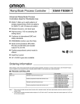
Digital Process Controller Series
E5K
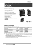
Advanced Process Digital
Controllers with Fuzzy Logic
D
D
D
D
D
D
D
D
D
D
D
D
Field configurable outputs, options.
100 ms sampling (for analog input).
Advanced PID, or fuzzy self-tuning.
Conforms to UL, CSA and CE standards.
Water-resistant front panel meets IP66/NEMA 4X.
Remote set point with optional event input board.
Set point ramp.
Serial communications available.
Front panel programming.
Heat only or heat/cool control.
Auxiliary outputs (SPST) standard; two for E5AK/E5EK,
one for E5CK.
3-year warranty.
R
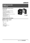
Ordering Information
Stock Note: Shaded models are normally stocked.
Note: Order Control Output Boards and Option Boards separately below.
Description
DIN size
1/4
/ DIN
(96 x 96 mm))
Standard model
Supply voltage
Model
100 to 240 VAC
E5AK-AA2-500
100 to 240 VAC
E5AK-PRR2-500
Standard model
24 VAC/VDC
E5AK-AA2-500 AC/DC24
Position-proportional model (See Note 3)
24 VAC/VDC
E5AK-PRR2-500 AC/DC24
100 to 240 VAC
E5EK-AA2-500
100 to 240 VAC
E5EK-PRR2-500
Standard model
24 VAC/VDC
E5EK-AA2-500 AC/DC24
Position-proportional model (See Note 3)
24 VAC/VDC
E5EK-PRR2-500 AC/DC24
100 to 240 VAC
E5CK-AA1-500
24 VAC/VDC
E5CK-AA1-500 AC/DC24
100 to 240 VAC
E5CK-AA1-302
Position-proportional model (See Note 3)
1/8
/ DIN
(48 x 96 mm))
Standard model
Position-proportional model (See Note 3)
1/16
/ DIN
(48 x 48 mm))
Standard model
Standard model
Non-standard model with built-in quick auto-tune button
(See Nomenclature section for details)
Note: 1. When using the heater burnout alarm function with a standard model, the Linear Output Module cannot be used for the control
outputs (heat). The Digital Controller provides transfer outputs at 4 to 20 mA for the PV and other values and control outputs at
4 to 20 mA for the current outputs.
2. E5EK-PRR2/E5AK-PRR2 controllers are supplied with dedicated relay output.
3. Position-proportional models are intended for motorized values (not 4-20 mA modulating valves). These use two relays (“open”
and “close”) which will turn a motor clockwise or counter-clockwise, thus opening or closing the valve.
4. Part numbers ending in --500 include a Finger Safe cover.
A--120
Digital Process Controller
E5K
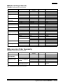
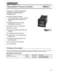
J Optional Output Boards
Stock Note: Shaded models are normally stocked.
Description
Specifications
Compatible
controller
Max. quantity
Model
Relay
SPST, 5 A, 250 VAC
E5AK/E5EK
2
E53-R
SSR (solid state relay)
1 A, 75 to 250 VAC
E5AK/E5EK
2
E53-S
Voltage
g pulse
p
NPN, 12 VDC
E5AK/E5EK
2
E53-Q
NPN, 24 VDC
E5AK/E5EK
2
E53-Q3
PNP, 24 VDC
E5AK/E5EK
2
E53-Q4
4 to 20 mA
E5AK/E5EK
2
E53-C3
0 to 20 mA
E5AK/E5EK
2
E53-C3D
0 to 10 VDC
E5AK/E5EK
2
E53-V34
0 to 5 VDC
E5AK/E5EK
2
E53-V35
Relay/Relay
SPST/SPST, 5 A, 250 VAC
E5CK
1
E53-R4R4
Relay/Pulse
y/
SPST, 5 A/NPN, 24 VDC
E5CK
1
E53-Q4R4
SPST, 5 A/PNP, 24 VDC
E5CK
1
E53-Q4HR4
SPST, 5 A/4 to 20 mA
E5CK
1
E53-C4R4
SPST, 5 A/0 to 20 mA
E5CK
1
E53-C4DR4
Relay/Linear voltage
SPST, 5 A/0 to 10 VDC
E5CK
1
E53-V44R4
Pulse/Pulse
/
NPN/NPN, 24 VDC
E5CK
1
E53-Q4Q4
PNP/PNP, 24 VDC
E5CK
1
E53-Q4HQ4H
RS-232C
E5AK/E5EK
3/1
E53-AK01
RS-232C
E5CK
1
E53-CK01
RS-422
E5AK/E5EK
3/1
E53-AK02
RS-485
E5AK/E5EK
3/1
E53-AK03
Linear current
Linear voltage
g
Relay/Linear
y/
current
Computer
communications
p
Event input
p
Transfer output
p
E5CK
1
E53-CK03
For remote set point
E5AK/E5EK
3/1
E53-AKB
For remote set point
E5CK
1
E53-CKB
4 to 20 mA
E5AK/E5EK
3/1
E53-AKF
4 to 20 mA
E5CK
1
E53-CKF
Note: If the control period is less than 5 seconds, use an SSR (solid state relay) or pulse voltage output.
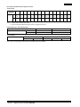
J Accessories (Order Separately)
Stock Note: Shaded models are normally stocked.
Description
Specifications
Current transformer; order
only if using heater
burnout alarm function
50 A load, 5.8 mm hole dia.
E5AK/E5EK
1
E54-CT1
120 A load, 12 mm hole dia.
E5AK/E5EK
1
E54-CT3
Terminal cover (supplied
( pp
with
ith St
Standard
d d models)
d l )
Provides finger
g p
protection
f
from
terminals
t
i l (VDE0106
part 100)
E5AK
1
E53-COV0809
E5CK
1
E53-COV07
E5EK
1
E53-COV08
All
1
Thermo Tools
(See Note)
Software
For setup and monitoring;
requires optional computer
communications board
Compatible
controller
Max. quantity
Model
Note: Contact Omron for current version information.
Digital Process Controller
E5K
A--121
Input Types (selectable with input jumper connector)
Thermocouple
K1
K2
J1
J2
T
°C
--200
to
1,300
0.0
to
500.0
--100
to
850
0.0
to
400.0
°F
--300
to
2,300
0.0
to
900.0
--100
to
1,500
0.0
to
750.0
Input (field
selectable)
(See Notes)
Range
E
L1
L2
U
N
R
S
B
W
PLII
--199.9
to
400.0
0
to
600
--100
to
850
0.0
to
400.0
--199.9
to
400.0
--200
to
1,300
0
to
1,700
0
to
1,700
100
to
1,800
0
to
2,300
0
to
1,300
--199.9
to
700.0
0
to
1,100
--100
to
1,500
0.0
to
750.0
--199.9
to
700.0
--300
to
2,300
0
to
3,000
0
to
3,000
300
to
3,200
0
to
4,100
0
to
2,300
Note: 1. Setting number is factory-set to 2 (K1).
2. Thermocouple W is W/Re5-26 (tungsten rhenium 5, tungsten rhenium 26).
Platinum Resistance Thermometer (RTD’s)
Input (field selectable)
Range
g
JPt100
Pt100
°C
--199.9 to 650.0
--199.9 to 650.0
°F
--199.9 to 999.9
--199.9 to 999.9
Current/Voltage
Current input
Input (field selectable)
4 to 20 mA
0 to 20 mA
Voltage input
1 to 5 V
Note: When a current/voltage input is selected, the decimal point is fully adjustable.
A--122
Digital Process Controller
E5K
0 to 5 V
0 to 10 V
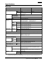
Specifications
J Ratings
Model
E5jK Standard
E5jK
Supply voltage
100--240 VAC, 50/60 Hz
24 VAC/VDC, 50/60 Hz
Operating voltage range
85% to 110% of rated supply voltage
85% to 110% of rated supply voltage
E5AK
16 VA
9 VA, 6 W
E5EK
15 VA
9 VA, 6 W
E5CK
10 VA (at 100 VAC)
14 VA (at 240 VAC)
6 VA, 3.5 W
Power consumption
p
Input
p
Thermocouple
K, J, T, E, L, U, N, R, S, B, W, PLII
Platinum resistance
thermometer (RTD)
JPt100, Pt100
Current input
4 to 20 mA, 0 to 20 mA
Voltage input
1 to 5 V, 0 to 5 V, 0 to 10 V
24V AC/DC
Mean Time Between Failure
15.4 years (135,000 hours)
Control output
(See Note 1)
SPST, 3 A at 250 VAC (resistive load)
Mechanical life expectancy: 10,000,000 operations min.
Electrical life expectancy:
100,000 operations min.
Auxiliary
y output
p
Relay
Voltage
g
( l )
(pulse)
NPN
20 mA at 12/24 VDC (with short-circuit protection)
PNP
20 mA at 24 VDC (with short-circuit protection)
Linear
voltage
Linear
current
cu
e t
0 to 10 VDC
Permissible load impedance: 1 kΩ min.
Resolution: Approximately 2600 steps
4 to 20 mA
Permissible load impedance: 500 Ω max.
Resolution: Approximately 2600 steps
0 to 20 mA
Permissible load impedance: 500 Ω max.
Resolution: Approximately 2600 steps
E5AK
3 A at 250 VAC (resistive load)
E5EK
3 A at 250 VAC (resistive load)
E5CK
1A at 250 VAC (resistive load)
SPST-NO
Control method (See Note 2)
ON/OFF, Advanced PID Control (with auto-tuning) or Self-tuning
Setting method
Digital setting using front panel keys or communications features
Indication method -- 7-seg. digital display and LEDs E5AK: PV = 15 mm, SP = 10.5 mm
E5EK: PV = 14 mm, SP = 9.5 mm
E5CK: PV = 12 mm, SP = 8 mm
100 Ω to 2.5 kΩ
Potentiometer for valve positioning
(for E5AK-PRR and E5EK-PRR only)
Event input
p
Contact
i
input
t
ON
1 kΩ max.
OFF
100 kΩ min.
No-contact
i
t
input
ON
residual voltage: 1.5 V max.
OFF
leakage current: 0.1 mA max.
4 to 20 mA, permissible load impedance: 600 Ω max.,
resolution: Approximately 2600 steps
Transmission output
Remote SP input
(for E5AK and E5EK only)
Current
input
4 to 20 mA (Input impedance: 150 Ω)
Current Transformer input (for E5AK and E5EK
only)
Connect only an Omron Current Transformer (E54-CT1 or E54-CT3)
Other functions
Standard
Manual output, heating/cooling control, SP limiter, loop burnout alarm, SP
ramp, MV limiter, MV change rate limiter, input digital filter, input shift,
run/stop, protect functions
Option
Multiple SP, run/stop selection, transfer output functions, auto/manual
Communications (RS-232C, RS-422, or RS-485), Loop Break Alarm, and
Transfer Output.
Standards
UL
File No.: E68481
CSA
File No.: LR59623
CE
File No.: EN50081-2; EN50082-2; IEC 1010-1
Note: 1. All control outputs are insulated from the input circuit.
2. Fuzzy self-tuning is available only when using the Digital Controller in standard control operation with temperature input.
Digital Process Controller
E5K
A--123
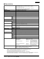
J Characteristics
Indication accuracy (See Note)
Thermocouple:
±0.3% of indication value or ±1°C, whichever is greater, ±1 digit max.
Platinum resistance thermometer:
±0.2% of indication value or ±0.8°C, whichever is greater, ±1 digit max.
Analog input: ±0.2% (of indication value) ±1 digit max.
Hysteresis
0.01% to 99.99% FS (in units of 0.01% FS)
Proportional band (P)
0.1% to 999.9% FS (in units of 0.1% FS)
Integral (reset) time (I)
0 to 3,999 s (in units of 1 s)
Derivative (rate) time (D)
0 to 3,999 s (in units of 1 s)
Control period
1 to 99 s (in units of 1 s)
Manual reset value
0.0% to 100.0% (in units of 0.1%)
Alarm setting range
Sampling period
--1,999 to 9,999 or --199.9 or 999.9 (decimal point position dependent on input type)
Temperature
input
250 ms scan rate
Analog
input
100 ms scan rate
Insulation resistance
200 MΩ min. (at 500 VDC)
Dielectric strength
Vibration resistance
Shock resistance
Ambient temperature
2,000 VAC, 50/60 Hz for 1 min between terminals of different polarities
Malfunction
10 to 55 Hz, 10 m/s2 (approx. 1G) for 10 min each in X, Y, and Z directions
Mechanical
10 to 55 Hz, 20 m/s2 (approx. 2G) for 2 hrs each in X, Y, and Z directions
Malfunction
200 m/s2 min. (approx. 20G), 3 times each in 6 directions
(100 m/s2 (approx. 10G) applied to the relay)
Mechanical
300 m/s2 min. (approx. 30G), 3 times each in 6 directions
Operating
--10°C to 55°C (14°F to 131°F ) with no icing; with 3-year warranty period: --10°C to 50°C
(14°F to 122°F )
Storage
--25°C to 65°C (--13°F to 149°F ) with no icing
Ambient humidity
Operating
35% to 85% RH
Enclosure ratings
g
Front panel
NEMA 4X for indoor use (equivalent to IP66)
Rear case
IEC standard IP20
Terminals
IEC standard IP00
Memory protection
Weight
g
EMC
Non-volatile memory (number of writings: 100,000 operations)
E5AK
Approx. 450 g
E5EK
Approx. 320 g
Mounting
bracket
Approx. 65 g
E5CK
Approx. 170 g
Adapter
Approx. 10 g
Emission Enclosure:
Emission AC Mains:
Immunity ESD:
Immunity RF-interference:
Immunity Conducted Disturbance:
Immunity Burst:
Standards -- Approvals
EN55011 Group 1 class A
EN55011 Group 1 class A
EN61000-4-2: 4 kV contact discharge (level 2)
8 kV air discharge (level 3)
ENV50140:
10 V/m (amplitude modulated,
80 MHz to 1 GHz) (level 3)
10 V/m (pulse modulated, 900
MHz)
ENV50141:
10 V (0.15 to 80 MHz) (level 3)
EN61000-4-4: 2 kV power-line (level 3)
2 kV I/O signal-line (level 4)
UL1092, CSA22.2 No. 14, CSA22.2 No. 1010-1
Conforms to EN50081-2, EN50082-2, EN61010-1 (IEC1010-1)
Conforms to VDE0106/part 100 (Finger Protection)
Note: Indication Accuracy -Of the K1, T, and N thermocouples at a temperature of -100°C or less: ±2°C ±1 digit maximum.
Of the U, L1, and L2 thermocouples at any temperature: ±2°C ±1 digit maximum.
Of the B thermocouple at a temperature of 400°C or less: unrestricted.
Of the R and S thermocouples at a temperature of 200°C or less: ±3°C ±1 digit maximum.
Of the W thermocouple at any temperature: ±0.3% of the indicated value or ±3°C, (whichever is greater) ±1 digit maximum.
Of the PLII thermocouple at any temperature: ±0.3% or ±2°C, whichever is greater ±1 digit maximum.
A--124
Digital Process Controller
E5K
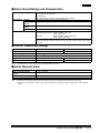
J Option Board Ratings and Characteristics
Event inputs
Contact input:
ON: 1 kΩ max., OFF: 100 kΩ min.
No-contact input:
ON: residual voltage 1.5 V max., OFF: leakage current 0.1 mA max.
Communications
Interface
RS-232C and RS-485; RS-422 for E5AK and E5EK only
Transmission
method
Half-duplex
Synchronization
method
Start-stop synchronization (asynchronous method)
Baud rate
1.2/2.4/4.8/9.6/19.2 kbps
Transfer output
4 to 20 mA:
Permissible load impedance: E5AK and E5EK = 600 Ω max.
E5CK = 500 Ω max.
Resolution:
E5AK and E5EK = approx. 2,600 steps
E5CK = approx. 2,600 steps
RS-232C Peer-to-peer only; maximum cable length = 15 m (49.2 feet)
RS-422 and RS-485 32 controller maximum to host computer; maximum cable length = 500 m
(1640 feet)
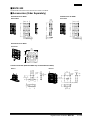
J Current Transformer Ratings
Part number
E54-CT1
E54-CT3
Max. continuous heater current
50 amps
120 amps (See Note 1)
Dielectric strength
1,000 VAC (for 1 min)
Vibration resistance
50 Hz, 98 m/s2 (10G)
Weight
Approx. 11.5 g
Approx. 50 g
Accessories
----
Armature: 2; Plug: 2
Note: 1. Use within the max. heater current rating of controller table shown below.
J Heater Burnout Alarm
Max. heater current
Single-phase 50 A AC
Heater current value display
accuracy
±5% FS ±1 digit max.
Heater burnout alarm setting range
0.1 to 49.9 A (in units of 0.1 A) (See Note 1)
Min. detection ON time
190 ms (See Note 2)
Note: 1. The heater burnout alarm is always OFF if the alarm is set to 0.0 A and always ON if the alarm is set to 50.0 A.
2. No heater burnout detection or heater current value measurement is possible if the control output (heat) is ON for less than
190 ms.
Digital Process Controller
E5K
A--125
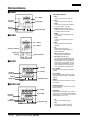
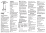
Nomenclature
J E5AK
Operation Indicators
No. 1 display
Operation
Indicators
No. 2 display
A/M Key
Display Key
Up Key/Down Key
•
OUT1
Lit when control output 1 turns ON.
•
OUT2
Lit when control output 2 turns ON.
•
SUB1
Lit when the output function assigned
to auxiliary output 1 turns ON.
•
SUB2 (for E5AK and E5EK only)
Lit when the output function assigned
to auxiliary output 2 turns ON.
•
MANU
Lit when the manual operation mode
is being used.
•
STOP
Lit when control operation has been
stopped.
•
RMT
Lit during remote communications
operation.
•
AT
Flashes during auto-tuning.
Auto-tuning is completed when this
LED stops flashing.
•
RSP (for E5AK and E5EK only)
Lit during remote SP operation.
•
Bar Graph (for E5AK only)
On a standard model (E5AK-AA2), this
bar graph indicates the manipulated
variable (heat) in 10% increments per
single segment. On a position-proportional model (E5AK-PRR2), this bar
graph indicates the valve opening in
10% increments per single segment.
J E5EK
No. 1 display
No. 2 display
Operation Indicators
Display Key
A/M Key
Up Key/Down Key
J E5CK
No. 1 display
No. 2 display
Operation
Indicators
No. 1 Display
Displays the process value or parameter
symbols.
No. 2 Display
Displays the set point, set point during SP
ramp, manipulated variable, or parameter
settings.
A/M Key
Display Key
Up Key/Down Key
A/M Key
Press to select the auto operation or manual operation.
J E5CK-302
Up Key/Down Key
Press to increase or decrease the value on
the No.2 display.
No. 1 display
No. 2 display
Operation
Indicators
AT Key
Display Key
A--126
Display Key
Press quickly (for less than 1 s) to shift the
display to the next parameter. When this key
is pressed for 1 s or more, the menu screen
will be displayed in any case.
•
AT
Press key for automatic tuning.
•
A/M
This feature is located in level one.
(Replaced AT feature in level one).
Up Key/Down Key
Digital Process Controller
E5K
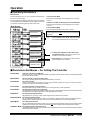
Operation
J Operating Parameters
Mode Selection
Press the Display Key for 1 sec. min. to switch to modes other than
the manual or protect mode.
The figure below (Menu Display) shows all modes in the order that
they are displayed. Some parameters are not displayed, depending
on the protect mode setting and the option boards used.
Menu Display
To Access Protect Mode
Press and hold the A/M Key and the Display Key for more than
1 second.
To Return to the Main PV/SP Display from the Protect Mode
Press and hold the A/M Key and the Display Key for more than
1 second.
To Access Manual Mode
Press and hold the A/M Key for more than 1 second.
1 second min.
Level 0 mode
To switch parameters within a mode, use the Display Key.
Press the display key for less than one second to move between
parameters.
Level 1 mode
Note:
1 second min.
1. In Level 0 mode, Level 1 mode, and Level 2 mode:
The controller will maintain control of the process.
Level 2 mode
Setup mode
Expansion mode
2. In Setup mode, Expansion mode, Option mode,
and Calibration mode: Control of the process is not
maintained. The outputs are inactive.
Option mode
3. Option Mode will be accessible only when an option
board is installed in the controller.
Calibration mode
J Parameters And Menus -- For Setting The Controller
Protect Mode
Limits use of the menu and A/M Keys.
The protect function prevents unwanted modification of parameters and can also be used to prevent switching between
the auto and manual operation.
Manual Mode
Sets the controller to manual operation mode.
You can only manually adjust the manipulated variable (MV) in this mode.
Level 0 Mode
For normal operation.
Change: the set point during operation, and start or stop Controller operation; and, (only in this mode) monitor the
process value, ramp SP, and manipulated variable.
Level 1 Mode
For adjusting primary control parameters.
Execute: AT (auto-tuning); set alarm values; set the control period; and, set PID parameters.
Level 2 Mode
For adjusting secondary control parameters.
Set parameters for: limiting the manipulated variable and set point; switch between the remote and local modes; set the
loop break alarm (LBA), alarm hysteresis, and the digital filter value of inputs.
Setup Mode
For setting the basic specifications.
Set parameters for: input type, scaling, output assignments and direct/reverse operation.
Expansion Mode
For setting expanded functions.
Set: ST (self-tuning), SP setting limiter. Select: advanced PID or ON/OFF control. Specify the standby sequence
resetting method. Initialize parameters; and, set the time for automatic return to the monitoring display.
Option Mode
For setting option functions.
Set: the communications conditions; transfer: output and event input parameters to match the type of Option Board
installed in the Controller. This mode will be accessible only when an option board is installed in the controller.
Calibration Mode For calibrating inputs and transfer output.
Calibrate the selected input type. Transfer output can be calibrated only when the Communications Unit (E53-CKF) has
been installed in the Controller.
Digital Process Controller
E5K
A--127
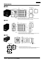
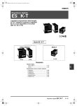
Dimensions
Unit: mm (inch)
J E5AK
13.5
(0.53)
110 min.
100 (3.94)
91 (3.58) x 91 (3.58)
112 (4.41)
96 (3.78) x 96 (3.78)
Panel Cutouts
120 min.
Note: 1. Recommended panel thickness is 1 to 8 mm.
2. Maintain the specified vertical and horizontal mounting space between each Unit.
Units must not be closely mounted vertically or horizontally.
J E5EK
13.5
(0.53)
48 (1.89)
Panel Cutouts
91 (3.58)
112 (4.41)
96
(3.78)
Note:
60 min.
100 (3.94)
120 min.
1. Recommended panel thickness is 1 to 8 mm.
2. Maintain the specified vertical and horizontal mounting space between each Unit.
Units must not be closely mounted vertically or horizontally.
J E5CK
13
(0.51)
100 (3.94)
48 (1.89)
58 (2.28)
53 (2.09) x 53 (2.09)
Panel Cutouts
44.8 (1.76) x 44.8 (1.76)
65 min.
Note:
60 min.
+0.6
1. Recommended panel thickness is 1 to 5 mm.
2. Maintain the specified vertical and horizontal mounting space between each Unit.
Units must not be closely mounted, either vertically or horizontally.
45 0
45 +0.6
0
A--128
Digital Process Controller
E5K
J E5CK-302
The E5CK-302 model has the same dimension and cutouts as the E5CK.
J Accessories (Order Separately)
Terminal Cover for E5EK
Terminal Cover for E5AK
E53-COV0809
43.2 (1.70)
3
3
3
1.5
3
1.5
89 (3.50)
89 (3.50)
43.2 (1.70)
E53-COV08
89 (3.50)
22.05
(0.87)
Terminal Cover for E5CK
E53-COV07
44.3
(1.74)
44.3
(1.74)
Current Transformer (E5AK and E5EK only for Heater Burnout Alarm)
E54-CT1
E54-CT3
21 (0.83)
15 (0.59)
5.8 dia.
(0.23)
2.36 dia.
2.8
(0.11)
30
(1.18)
7.5 (0.30)
3
25
(0.98) (0.12)
12 dia.
(0.47)
40 (1.57)
x 40 (1.57)
40 (1.57)
Two, M3 (depth: 4)
10
(0.39)
15
30 (1.18)
30
(1.18)
Digital Process Controller
E5K
A--129
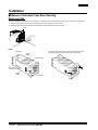
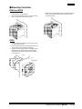
Installation
J Remove Controller From Rear Housing
E5AK and E5EK
To pull out the internal mechanism from the housing, use a Phillips screwdriver matching the screw on the lower part of the front panel.
1. Turn the screw counterclockwise while pressing the hook on the upper part of the front panel.
2. Carefully pull out the internal mechanism while holding the left and right sides of the front panel.
Hook
E5CK
Terminals
First, while pressing the hooks on the left and right sides of the
front panel, pull the internal mechanism from the housing.
Output
Board
Housing (case)
Input Type
Jumper Connector
Option
Board
A--130
Digital Process Controller
Front Panel
E5K
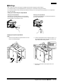
J Settings
Note: Always turn off the power supply to the Digital Controller before changing any switch settings.
On a standard model, set up the Output Modules for control outputs 1 and 2 before mounting the Controller.
On a position-proportional model, the Relay Output Module is already set. Do not change that set-up parameter. Do not replace with
other Output Modules.
Setting Up and Removing the Output Module
Setting Up the Output Module
Removing the Output Module
When setting up the Output Modules, pull out the internal
mechanism from the housing and insert the Output Modules
into the sockets for control outputs 1 and 2.
To replace the Output Module, use a flat-blade screwdriver to
push up the Output Module.
Setting Up the Option/Output Board
E5AK
1. Remove the Power Board and Option Boards in the order
shown in the following diagram.
Power
board
2. Insert the Option Boards into the sockets for options 1 to 3.
The following diagram shows the relationship between the
Option Boards and mounting positions.
Option
board
3. Mount the option boards and the power board in the
order shown.
Digital Process Controller
E5K
A--131
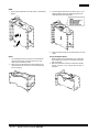
E5EK
1. Remove the Power Board in the order shown in the following
diagram.
2. Insert the Option Board into the socket for option 1. The
following diagram shows the relationship between the
Option Board and mounting position.
Power
board
3. Mount the option boards and the power board in the order
shown.
E5CK
Set up the Option Board
1. Two rectangular holes are provided on the Power Board
(right side of Controller). Fit the two protrusions of the
output board into these two holes.
2. With the output board fitted into the Power Board, fit the
output board into the connector on the control board (left
side of Controller).
1. Place the bottom of the Controller facing up, fit the board
horizontally into the connector on the power board (right
side of controller).
2. With the Power Board connected, fit the board vertically
into the connector on the control board (left side of
Controller).
1
1
2
2
A--132
Digital Process Controller
E5K
J Mounting Controller
E5AK and E5EK
1. Insert the controller into the panel’s mounting hole at the
position shown in the figure below.
2. Fit the mounting bracket (accessory) into the mounting
slots on the top and bottom of the rear case.
3. Tighten the mounting bracket screws on the upper and lower
parts in small increments alternately and equally until the
ratchet start to slide.
E5CK
1. Insert the E5CK Controller into the cutout on the panel,
as shown in the figure here.
2. Push the adapter along the Controller body from the terminals up to the panel, and fasten temporarily.
3. Tighten the two mounting screws on the adapter. When
tightening screws, tighten the two screws alternately
keeping the torque to approximately 0.29 to 0.39 N S m,
or 3 to 4 kgf S cm.
Adapter
Panel
Watertight gasket
Digital Process Controller
E5K
A--133
J Mounting Terminal Cover
E5AK and E5EK
E5CK
1. Fasten the terminals covers as follows by using the plastic
pins. Plastic pins are provided with the terminal covers.
1. The E5CK-AA1-500 Controller is provided with a Terminal
Cover (E53-COV07). Fasten the Terminal Cover as follows by using the plastic pin.
E5CK
E53--COV07
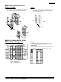
J Wiring Terminals for E5AK
Wiring
E5AK Terminal Arrangement
In the following wiring diagrams, the left side of the terminal
numbers indicate the inside of the Controller.
AC100--240V~
50/60 Hz
OPTION
2
OPTION
1
OPTION
3
SENSOR
INPUT
TRSF:
EV1 to 4:
PTMR:
RSP:
A--134
Transfer output
Event input
Potentiometer
Remote SP input
Digital Process Controller
E5K
Power Supply
Input power to terminal numbers 9 and 10. Power specifications
are as follows: 100 to 240 VAC, 50/60 Hz, approx. 16 VA
Wiring Terminals for E5EK
Power supply
E5EK Terminal Arrangement
Input power to terminal numbers 9 and 10. Power specifications
are as follows: 100 to 240 VAC, 50/60 Hz, approx. 15 VA
AC100--240V~
50/60 Hz
OPTION
1
SENSOR
INPUT
TRSF:
EV1/2:
PTMR:
RSP:
Transfer output
Event input
Potentiometer
Remote SP input
J Wiring Terminals for E5CK
E5CK Terminal Arrangement
Wiring Precautions
•
OUT1
•
•
100--240VAC
5
11
12
10
OUT2
4
9
3
8
2
7
SUB1
1
13
OPTION
14
6
To protect the Controller and its lines from external noise, use
the wire ducts to separate input leads and power lines.
Use solderless terminals when wiring the Controller.
Tighten the terminal screws using a torque no greater than
0.78 N S m, or 8 kgf S cm max. DO NOT tighten the terminal
screws too tightly.
Power Supply
INPUT
Input 100 to 240 VAC to terminal numbers 4 and 5.
5
11
12
10
4
9
3
8
2
1
7
13
14
6
Digital Process Controller
E5K
A--135
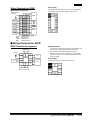
J Input Wiring
E5AK
Connect the sensor input to terminal numbers 11 to 14 and 33 as follows according to the input type.
E5EK
Connect the sensor input to terminal numbers 11 to 14 and 23 as follows according to the input type.
E5CK
Connect the sensor input to terminal numbers 6 to 8 as indicated here, according to the input type.
5
11
12
10
4
9
3
8
2
7
1
13
14
-
8
8
7
7
-
8
7
V
+
Input type
6
6
Thermocouple
6
Platinum resistance
thermometer (RTD)
8
-
+
7
mA
6
Voltage input
6
+
Current input
Internal jumper
setting
TC ⋅ PT
V
I
Match the inputs with the internal jumper settings for each input type. For thermocouple or platinum resistance thermometer inputs, set
the internal jumper to a common position (TC/PT) as the temperature input.
A--136
Digital Process Controller
E5K
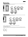
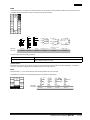
J Control Output
E5AK Control Output
Terminal numbers 7 and 8 are for control output 1 (OUT1), and terminal numbers 5 and 6 are for control output 2 (OUT2). The following
diagrams show the available Output Modules and their internal circuits.
E5EK Control Output
Terminal numbers 7 and 8 are for control output 1 (OUT1), and terminal numbers 5 and 6 are for control output 2 (OUT2). The following
diagrams show the available Output Modules and their internal circuits.
With E53-Vjj Output Modules, approx. 2 V is output for one second after the power is interrupted.
E5AK-PRR2/E5EK-PRR2 Controllers
The E5AK-PRR2 and E5EK-PRR2 Controllers are supplied with relay output. This relay output is not compatible with any other module.
When replacing the Output Module, use the E53-R. The following diagrams show the relationship between terminals and open/close relay
settings.
8
7
Open
6
5
Close
Digital Process Controller
E5K
A--137
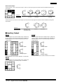
E5CK Control Output
Terminal numbers 11 and 12 are for control output 1 (OUT1). The five output types and internal circuits are available according to the
Output Board.
5
11
12
10
3
8
2
7
13
14
+
11
6
12
-
Output type
Relay
NPN
Part number
E53-R4R4
E53-Q4R4
E53-Q4Q4
L
V
L
GND
12
+
11
11
L
12
+
11
9
4
1
+
+
v
11
12
-
PNP
L
12
-
0 to 10 V
E53-Q4HR4
E53-Q4HQ4H
mA
-
4 to 20 mA/0 to 20 mA
E53-V44R4
E53-C4R4
E53-C4DR4
Terminal numbers 9 and 10 are for control output 2 (OUT2). The three output types and internal circuits are available according to the
Output Board.
+
10
+v
+
10
10
L
9
9
L
GND
-
Output type
Relay
NPN
Part number
E53-R4R4 /E53-V44R4
E53-Q4R4 /E53-C4R4
E53-Q4HR4/E53-C4DR4
E53-Q4Q4
9
-
PNP
E53-Q4HQ4H
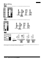
J Auxiliary Output
E5AK
E5EK
Terminal numbers 3 and 4 are for auxiliary output 1 (SUB1) and
terminal numbers 1 and 2 are for auxiliary output 2 (SUB2). The
following diagrams show the internal equalizing circuits for the
auxiliary outputs:
Terminal numbers 3 and 4 are for auxiliary output 1 (SUB1) and
terminal numbers 1 and 2 are for auxiliary output 2 (SUB2). The
following diagrams show the internal equalizing circuits for the
auxiliary outputs:
10
9
8
7
6
5
4
3
2
1
30 31 32
29
28
27
26
25
24
23
22
21 33
20
19
18
17
16
15
14
13
12
11
4
3
Auxiliary output 1
2
1
Auxiliary output 2
Output specifications are as follows: SPST-NO, 3 A at 250 VAC
E5CK
Terminal numbers 2 and 3 are for auxiliary output 1 (SUB1). The
internal equalizing circuit for auxiliary output 1 is as follows:
5
11
12
10
4
9
3
8
3
2
1
7
13
A--138
14
2
6
Digital Process Controller
E5K
10 21 22
9
8
7
6
5
4
3
2
1 23
20
19
18
17
16
15
14
13
12
11
4
3
Auxiliary output 1
2
1
Auxiliary output 2
Output specifications are as follows: SPST-NO, 3 A at 250 VAC
J CT Input/Potentiometer (for E5AK and E5EK only)
E5AK CT Input/Potentiometer
E5EK CT Input/Potentiometer
When using the HBA function on the E5AK-AA2 Controller,
connect Current Transformer input (CT) to terminal numbers 15
to 17. When monitoring the valve opening on the E5AK-PRR2
Controller, connect the potentiometer (PTMR) to terminal
numbers 15 to 17. Connect each of these inputs as follows:
When using the HBA function on the E5EK-AA2 Controller,
connect Current Transformer input (CT) to terminal numbers 15
to 17. When monitoring the valve opening on the E5EK-PRR2
Controller, connect the potentiometer (PTMR) to terminal
numbers 15 to 17. Connect each of these inputs as follows:
10
9
8
7
6
5
4
3
2
1
30 31 32
29
28
27
26
25
24
23
22
21 33
20
19
18
17
16
15
14
13
12
11
17
CT
16
15
CT input
O
17
W
16
C
15
Potentiometer
For details on CT inputs, refer to Appendix, About Current
Transformer in your User’s Manual. For details on the
potentiometer, refer to the Instruction Manual for the valve
connected to the Controller. The variable resistance range is
100 Ω to 2.5 kΩ.
10 21 22
9
8
7
6
5
4
3
2
1 23
20
19
18
17
16
15
14
13
12
11
17
CT
16
15
CT input
O
17
W
16
C
15
Potentiometer
For details on CT inputs, refer to Appendix, About Current
Transformer in your User’s Manual. The potentiometer cannot be
used simultaneously with remote SP input. For details on the
potentiometer, refer to the Instruction Manual for the valve
connected to the Controller. The variable resistance range is 100
Ω to 2.5 kΩ.
J Remote Set Point Input (for E5AK and E5EK only)
E5AK Remote SP Input
E5EK Remote SP Input
Connect the input (RSP) to be used as the remote SP to terminal
numbers 21 and 22. Only 4 to 20 mA inputs can be connected.
Connect the input as follows:
Connect the input (RSP) to be used as the remote SP to terminal
numbers 15 and 16. However, note that the potentiometer cannot
be used simultaneously with remote SP input. Only 4 to 20 mA
inputs can be connected. Connect the input as follows:
10
9
8
7
6
5
4
3
2
1
30 31 32
29
28
27
26
25
24
23
22
21 33
20
19
18
17
16
15
14
13
12
11
22
+
4 to 20 mA
21
--
10 21 22
9
8
7
6
5
4
3
2
1 23
20
19
18
17
16
15
14
13
12
11
16
+
4 to 20 mA
15
--
Digital Process Controller
E5K
A--139
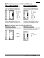
J Option Board Wiring
E5AK
Connect event inputs 1 and 2 (EV1/2) to terminal numbers 18 to 20, and event events 3 and 4 (EV3/4) to terminal numbers 24 to 26.
However, note that terminal numbers 18 to 20 cannot be used on Controllers with a communications function. Connect the event inputs as
follows:
10
9
8
7
6
5
4
3
2
1
30 31 32
29
28
27
26
25
24
23
22
21 33
20
19
18
17
16
15
14
13
12
11
Terminals 18 and 24 (COM) are connected internally.
SD
20
32
RD
19
18
31
SG
19
20
18
SDA
SDB
RDA
RDB
32
31
19
20
A
+
B
EV1
+
A
B
EV2
EV3
26
EV4
25
+
19
COM 18
--
+
+
20
COM 24
30
L
4 to 20 mA
29
--
--
SG
Option type
RS-232C
RS-422
RS-485
Part number
E53-AK01
E53-AK02
E53-AK03
Event input 1 and 2
(no contact)
Event input 3 and 4
(no contact)
Transfer output
Use event inputs under the following conditions:
Contact input
ON: 1 kΩ max.
OFF: 100 kΩ min.
No-contact input
ON: Residual voltage 1.5 V max.,
OFF: Leakage current 0.1 mA max.
Communications
Terminal numbers 18 to 20, 31 and 32 can be used only on Controllers with Communications Units (E53-AK01/02/03). For details on wiring, refer to Chapter 6, Using the Communications Function in your User’s Manual.
A--140
Digital Process Controller
E5K
E5EK
Connect event inputs 1 and 2 (EV1/2) to terminal numbers 18 to 20. However, note that terminal numbers 18 to 20 cannot be used on
Controllers with a communications function. Connect the event inputs as follows:
10 21 22
9
8
7
6
5
4
3
2
1 23
20
19
18
17
16
15
14
13
12
11
22
SD
20
21
RD
19
19
SG
18
20
18
SDA
A
22
SDB
RDA
RDB
EV2 19
+
21
20
+
COM 18
B
20
EV1
EV1 20
A
19
+
+
B
21
+
EV2
--
COM 18
L
4 to 20 mA
19
22
--
--
SG
Option type
RS-232C
RS-422
RS-485
Event input 1 and 2
Part number
E53-AK01
E53-AK02
E53-AK03
E53-AKB
Event input 1 and 2
(no contact)
E53-AKB
Transfer output
E53-AKF
Use event inputs under the following conditions:
Contact input
ON: 1 kΩ max., OFF: 100 kΩ min.
No-contact input
ON: Residual voltage 1.5 V max.,
OFF: Leakage current 0.1 mA max.
Communications
Terminal numbers 18 to 20, 31 and 32 can be used only on Controllers with Communications Units (E53-AK01/02/03). For details on
wiring, refer to Chapter 6, Using the Communications Function in your User’s Manual.
E5CK
Terminal numbers 1, 13, and 14 are valid only when the Option Board is set in the Controller
The following four connections are possible depending on the model of the Option Board.
5
11
12
4
10
13
9
3
8
2
7
1
13
14
6
14
1
+SD
-RD
SG
+
A+
13
13
14
14
14
1
1
1
13
4 to 20 mA
B --
Option type
RS-232C
RS-485
Event input
Part number
E53-CK01
E53-CK03
E53-CKB
--
Transfer output
E53-CKF
Digital Process Controller
E5K
A--141
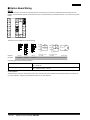
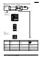
J Connection Example of Digital Controller And SSR
SSR
Digital Controller
Load
+
+
Voltage output
terminal (for driving SSR)
Heater
INPUT
--
LOAD
Power supply
for load
-Connectable
Power SSR
E5AK/E5EK
Digital Controller with
Voltage Output
(12 VDC, 40 mA max.)
E5CK
Digital Controller with
Voltage Output
(12 VDC, 20 mA max.)
Model
G3PA/G3PB
G3NA
G3NE
SSRs
connected
in parallel
E5AK/E5EK: 8 pcs.
E5CK: 4 pcs.
E5AK/E5EK: 5 pcs.
E5CK: 2 pcs.
E5AK/E5EK: 2 pcs.
E5CK: 1 piece
Rated
input
voltage
5 to 24 VDC
5 to 24 VDC
12 VDC
Features
Thin, SSR with built-in heat sink;
1-phase and 3-phase models
Standard model with screw terminals
Compact, low-cost model with tab
terminals
Appearance
A--142
Digital Process Controller
E5K
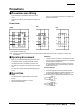
Precautions
J Precautions when Wiring
•
•
•
Use wire ducts to separate input leads and power lines in
order to protect the Controller and its lines from external
noise.
Solderless terminals are recommended when wiring the Controller.
Tighten the terminal screws using a torque no greater than
0.78 N S m, or 8 kgf S cm max. Take care not to tighten the
terminal screws too tightly.
Power Blocks
The E5AK/E5EK has independent power supplies for each of the terminal blocks shown below.
E5EK
E5AK
E5CK
*
10
9
8
7
6
5
4
3
2
1
*
30 31 32
29
28
27
26
25
24
23
22
21 33
20
19
18
17
16
15
14
13
12
11
*
10 21 22
9
8
7
6
5
4
3
2
1 23
*
*
20
19
18
17
16
15
14
13
12
11
5 11 12 10
4
9
3
8
2
7
*
1 13 14 6
* Uses same internal power supply
Note: Terminals 21 and 22 of the E5EK belong to the B block when a transfer output is set to option 1 and to the C block for other
Option Boards.
J Operating Environment
•
•
•
•
Keep within the rated ambient operating temperature, ambient operating humidity, and storage temperature ranges.
Use the Unit according to the vibration resistance, shock
resistance, and enclosure ratings.
Do not use the Unit in places with corrosive gas or excessive
dust.
Do not use the Unit near machines generating high-frequency noise.
J Correct Use
Mounting
•
•
•
The dimensions of the Digital Controller conform to DIN
43700.
Recommended panel thickness is 1 to 8 mm.
Mount the Unit horizontally.
Connection
•
•
To reduce inductive noise influence, the lead wires connecting the input type to the Digital Controller must be separated
from the power lines and load lines.
Use the specified compensating conductors for thermocouples. Use lead wires having a small resistance for platinum
resistance thermometers.
Connection Example
•
•
Wire the terminals of the Unit using solderless terminals.
The tightening torque applied to the terminal screws of the
Unit must be approximately 0.78 N S m or 8 kgf S cm.
Use the following type of solderless terminals for M3.5 screws.
7.2 mm max.
7.2 mm max.
Digital Process Controller
E5K
A--143
J Operation
• For models with alarm functions: The alarm outputs of a model with an alarm function may not turn ON properly when the
model malfunctions. The use of alarm equipment with the
model is recommended.
• The parameters and internal switch are set before shipping so
that the Unit will function normally. Change the settings of the
parameters and internal switch according to the application, if
necessary.
• Several seconds are required until the relay is turned ON after
power has been supplied to the Digital Controller. You must
take this time delay into consideration when designing sequenced circuits which incorporate a Digital Controller.
A--144
Digital Process Controller
E5K
• Do not use excessive force when pulling out the internal
mechanism from the housing. Protect the internal connector or
electronic parts of the Unit from shock. Protect against static
discharge when changing the settings of the internal switch.
Changing the settings on a grounded conductive mat is recommended.
• When connecting the Control Output Unit to the Temperature
Controller or Digital Controller, make sure that the Control
Output Unit is a suitable type. The use of an improper type of
Control Output Unit may cause the system to malfunction.
• The heater burnout alarm will not be available if the Linear
Output Unit is used.
Digital Process Controller
E5K
A--145
&HUWDLQ7HUPVDQG&RQGLWLRQVRI6DOH
2IIHU $FFHSWDQFH 7KHVH WHUPV DQG FRQGLWLRQV WKHVH 7HUPV DUH GHHPHG
SDUWRIDOOFDWDORJVPDQXDOVRURWKHUGRFXPHQWVZKHWKHUHOHFWURQLFRULQZULW
LQJ UHODWLQJ WR WKH VDOH RI JRRGV RU VHUYLFHV FROOHFWLYHO\ WKH *RRGV E\
2PURQ(OHFWURQLFV//&DQGLWVVXEVLGLDU\FRPSDQLHV6HOOHU6HOOHUKHUHE\
REMHFWVWRDQ\WHUPVRUFRQGLWLRQVSURSRVHGLQ%X\HU
VSXUFKDVHRUGHURURWKHU
GRFXPHQWVZKLFKDUHLQFRQVLVWHQWZLWKRULQDGGLWLRQWRWKHVH7HUPV3OHDVH
FRQWDFW \RXU 2PURQ UHSUHVHQWDWLYH WR FRQILUP DQ\ DGGLWLRQDO WHUPV IRU VDOHV
IURP\RXU2PURQFRPSDQ\
3ULFHV $OO SULFHV VWDWHG DUH FXUUHQW VXEMHFW WR FKDQJH ZLWKRXW QRWLFH E\
6HOOHU%X\HUDJUHHVWRSD\WKHSULFHLQHIIHFWDWWLPHRIVKLSPHQW
'LVFRXQWV &DVK GLVFRXQWV LI DQ\ ZLOO DSSO\ RQO\ RQ WKH QHW DPRXQW RI
LQYRLFHV VHQW WR %X\HU DIWHU GHGXFWLQJ WUDQVSRUWDWLRQ FKDUJHV WD[HV DQG
GXWLHVDQGZLOOEHDOORZHGRQO\LILWKHLQYRLFHLVSDLGDFFRUGLQJWR6HOOHU
V
SD\PHQWWHUPVDQGLL%X\HUKDVQRSDVWGXHDPRXQWVRZLQJWR6HOOHU
2UGHUV6HOOHUZLOODFFHSWQRRUGHUOHVVWKDQQHWELOOLQJ
*RYHUQPHQWDO $SSURYDOV %X\HU VKDOO EH UHVSRQVLEOH IRU DQG VKDOO EHDU DOO
FRVWVLQYROYHGLQREWDLQLQJDQ\JRYHUQPHQWDSSURYDOVUHTXLUHGIRUWKHLPSRU
WDWLRQRUVDOHRIWKH*RRGV
7D[HV$OOWD[HVGXWLHVDQGRWKHUJRYHUQPHQWDOFKDUJHVRWKHUWKDQJHQHUDO
UHDO SURSHUW\ DQG LQFRPH WD[HV LQFOXGLQJ DQ\ LQWHUHVW RU SHQDOWLHV WKHUHRQ
LPSRVHGGLUHFWO\ RULQGLUHFWO\RQ 6HOOHU RUUHTXLUHGWR EHFROOHFWHGGLUHFWO\RU
LQGLUHFWO\E\6HOOHUIRUWKHPDQXIDFWXUHSURGXFWLRQVDOHGHOLYHU\LPSRUWDWLRQ
FRQVXPSWLRQ RU XVH RI WKH *RRGV VROG KHUHXQGHU LQFOXGLQJ FXVWRPV GXWLHV
DQG VDOHV H[FLVH XVH WXUQRYHU DQG OLFHQVH WD[HV VKDOO EH FKDUJHG WR DQG
UHPLWWHGE\%X\HUWR6HOOHU
)LQDQFLDO,IWKHILQDQFLDOSRVLWLRQRI%X\HUDWDQ\WLPHEHFRPHVXQVDWLVIDFWRU\
WR 6HOOHU 6HOOHU UHVHUYHV WKH ULJKW WR VWRS VKLSPHQWV RU UHTXLUH VDWLVIDFWRU\
VHFXULW\RUSD\PHQWLQDGYDQFH,I%X\HUIDLOVWRPDNHSD\PHQWRURWKHUZLVH
FRPSO\ZLWKWKHVH7HUPVRUDQ\UHODWHGDJUHHPHQW6HOOHUPD\ZLWKRXWOLDELOLW\
DQGLQDGGLWLRQWRRWKHUUHPHGLHVFDQFHODQ\XQVKLSSHGSRUWLRQRI*RRGVVROG
KHUHXQGHUDQGVWRSDQ\*RRGVLQWUDQVLWXQWLO%X\HUSD\VDOODPRXQWVLQFOXG
LQJDPRXQWVSD\DEOHKHUHXQGHUZKHWKHURUQRWWKHQGXHZKLFKDUHRZLQJWRLW
E\%X\HU%X\HUVKDOOLQDQ\HYHQWUHPDLQOLDEOHIRUDOOXQSDLGDFFRXQWV
&DQFHOODWLRQ (WF 2UGHUV DUH QRW VXEMHFW WR UHVFKHGXOLQJ RU FDQFHOODWLRQ
XQOHVV%X\HU LQGHPQLILHV6HOOHUIXOO\DJDLQVWDOOFRVWV RUH[SHQVHVDULVLQJLQ
FRQQHFWLRQWKHUHZLWK
)RUFH 0DMHXUH 6HOOHU VKDOO QRW EH OLDEOH IRU DQ\ GHOD\ RU IDLOXUH LQ GHOLYHU\
UHVXOWLQJIURPFDXVHVEH\RQGLWVFRQWUROLQFOXGLQJHDUWKTXDNHVILUHVIORRGV
VWULNHV RU RWKHU ODERU GLVSXWHV VKRUWDJH RI ODERU RU PDWHULDOV DFFLGHQWV WR
PDFKLQHU\ DFWV RI VDERWDJH ULRWV GHOD\ LQ RU ODFN RI WUDQVSRUWDWLRQ RU WKH
UHTXLUHPHQWVRIDQ\JRYHUQPHQWDXWKRULW\
6KLSSLQJ'HOLYHU\8QOHVVRWKHUZLVHH[SUHVVO\DJUHHGLQZULWLQJE\6HOOHU
D 6KLSPHQWVVKDOOEHE\DFDUULHUVHOHFWHGE\6HOOHU
E 6XFKFDUULHUVKDOODFWDVWKHDJHQWRI%X\HUDQGGHOLYHU\WRVXFKFDUULHU
VKDOOFRQVWLWXWHGHOLYHU\WR%X\HU
F $OOVDOHVDQGVKLSPHQWVRI*RRGVVKDOOEH)2%VKLSSLQJSRLQWXQOHVVRWK
HUZLVHVWDWHGLQZULWLQJE\6HOOHUDWZKLFKSRLQWWLWOHWRDQGDOOULVNRIORVVRI
WKH*RRGVVKDOOSDVVIURP6HOOHUWR%X\HUSURYLGHGWKDW6HOOHUVKDOOUHWDLQD
VHFXULW\LQWHUHVWLQWKH*RRGVXQWLOWKHIXOOSXUFKDVHSULFHLVSDLGE\%X\HU
G 'HOLYHU\DQGVKLSSLQJGDWHVDUHHVWLPDWHVRQO\
H 6HOOHUZLOOSDFNDJH*RRGVDVLWGHHPVSURSHUIRUSURWHFWLRQDJDLQVWQRUPDO
KDQGOLQJDQGH[WUDFKDUJHVDSSO\WRVSHFLDOFRQGLWLRQV
&ODLPV $Q\ FODLP E\ %X\HU DJDLQVW 6HOOHU IRU VKRUWDJH RU GDPDJH WR WKH
*RRGVRFFXUULQJEHIRUHGHOLYHU\WRWKHFDUULHUPXVWEHSUHVHQWHGLQZULWLQJWR
6HOOHUZLWKLQGD\VRIUHFHLSWRIVKLSPHQWDQGLQFOXGHWKHRULJLQDOWUDQVSRUWD
WLRQELOOVLJQHGE\WKHFDUULHUQRWLQJWKDWWKHFDUULHUUHFHLYHGWKH*RRGVIURP
6HOOHULQWKHFRQGLWLRQFODLPHG
:DUUDQWLHV D ([FOXVLYH :DUUDQW\ 6HOOHU
V H[FOXVLYH ZDUUDQW\ LV WKDW WKH
*RRGVZLOOEHIUHHIURPGHIHFWVLQPDWHULDOVDQGZRUNPDQVKLSIRUDSHULRGRI
WZHOYHPRQWKVIURPWKHGDWHRIVDOHE\6HOOHURUVXFKRWKHUSHULRGH[SUHVVHG
LQZULWLQJE\6HOOHU6HOOHUGLVFODLPVDOORWKHUZDUUDQWLHVH[SUHVVRULPSOLHG
E/LPLWDWLRQV6(//(50$.(612:$55$17<255(35(6(17$7,21
(;35(66 25 ,03/,(' $%287 121,1)5,1*(0(17 0(5&+$17$%,/
,7< 25 ),71(66 )25 $ 3$57,&8/$5 385326( 2) 7+( *22'6
%8<(5$&.12:/('*(67+$7,7$/21(+$6'(7(50,1('7+$77+(
*22'6 :,// 68,7$%/< 0((7 7+( 5(48,5(0(176 2) 7+(,5
,17(1'('86(6HOOHUIXUWKHUGLVFODLPVDOOZDUUDQWLHVDQGUHVSRQVLELOLW\RI
DQ\W\SHIRUFODLPVRUH[SHQVHVEDVHGRQLQIULQJHPHQWE\WKH*RRGVRURWKHU
ZLVHRIDQ\LQWHOOHFWXDOSURSHUW\ULJKWF%X\HU5HPHG\6HOOHU
VVROHREOLJD
WLRQ KHUHXQGHU VKDOO EH WR UHSODFH LQ WKH IRUP RULJLQDOO\ VKLSSHG ZLWK %X\HU
UHVSRQVLEOH IRU ODERU FKDUJHV IRU UHPRYDO RU UHSODFHPHQW WKHUHRI WKH QRQ
FRPSO\LQJ *RRG RU DW 6HOOHU
V HOHFWLRQ WR UHSD\ RU FUHGLW %X\HU DQ DPRXQW
HTXDOWRWKHSXUFKDVHSULFHRIWKH*RRGSURYLGHGWKDWLQQRHYHQWVKDOO6HOOHU
EHUHVSRQVLEOHIRUZDUUDQW\UHSDLULQGHPQLW\RUDQ\RWKHUFODLPVRUH[SHQVHV
UHJDUGLQJ WKH *RRGV XQOHVV 6HOOHU
V DQDO\VLV FRQILUPV WKDW WKH *RRGV ZHUH
SURSHUO\KDQGOHGVWRUHGLQVWDOOHGDQGPDLQWDLQHGDQGQRWVXEMHFWWRFRQWDPL
QDWLRQDEXVHPLVXVHRULQDSSURSULDWHPRGLILFDWLRQ5HWXUQRIDQ\JRRGVE\
%X\HUPXVWEHDSSURYHGLQZULWLQJE\6HOOHUEHIRUHVKLSPHQW6HOOHUVKDOOQRW
EHOLDEOHIRUWKHVXLWDELOLW\RUXQVXLWDELOLW\RUWKHUHVXOWVIURPWKHXVHRI*RRGV
LQ FRPELQDWLRQ ZLWK DQ\ HOHFWULFDO RU HOHFWURQLF FRPSRQHQWV FLUFXLWV V\VWHP
DVVHPEOLHV RU DQ\ RWKHU PDWHULDOV RU VXEVWDQFHV RU HQYLURQPHQWV $Q\
DGYLFHUHFRPPHQGDWLRQVRULQIRUPDWLRQJLYHQRUDOO\RULQZULWLQJDUHQRWWREH
FRQVWUXHGDVDQDPHQGPHQWRUDGGLWLRQWRWKHDERYHZDUUDQW\
'DPDJH/LPLWV(WF6(//(56+$//127%(/,$%/()2563(&,$/,1',
5(&7 25 &216(48(17,$/ '$0$*(6 /266 2) 352),76 25 352
'8&7,2125&200(5&,$//266,1$1<:$<&211(&7(':,7+7+(
*22'6:+(7+(568&+&/$,0,6%$6(',1&2175$&7:$55$17<
1(*/,*(1&( 25 675,&7 /,$%,/,7< )XUWKHU LQ QR HYHQW VKDOO OLDELOLW\ RI
6HOOHUH[FHHGWKHLQGLYLGXDOSULFHRIWKH*RRGRQZKLFKOLDELOLW\LVDVVHUWHG
,QGHPQLWLHV%X\HUVKDOOLQGHPQLI\DQGKROGKDUPOHVV6HOOHULWVDIILOLDWHVDQG
LWV HPSOR\HHV IURP DQG DJDLQVW DOO OLDELOLWLHV ORVVHV FODLPV FRVWV DQG
H[SHQVHVLQFOXGLQJDWWRUQH\
VIHHVDQGH[SHQVHVUHODWHGWRDQ\FODLPLQYHV
WLJDWLRQOLWLJDWLRQRUSURFHHGLQJZKHWKHURUQRW6HOOHULVDSDUW\ZKLFKDULVHV
RULVDOOHJHGWRDULVHIURP%X\HU
VDFWVRURPLVVLRQVXQGHUWKHVH7HUPVRULQ
DQ\ZD\ZLWKUHVSHFWWRWKH*RRGV:LWKRXWOLPLWLQJWKHIRUHJRLQJ%X\HUDW
LWVRZQH[SHQVHVKDOOLQGHPQLI\DQGKROGKDUPOHVV6HOOHUDQGGHIHQGRUVHWWOH
DQ\DFWLRQEURXJKWDJDLQVW6HOOHUWRWKHH[WHQWWKDWLWLVEDVHGRQDFODLPWKDW
DQ\*RRGPDGHWR%X\HUVSHFLILFDWLRQVLQIULQJHGLQWHOOHFWXDOSURSHUW\ULJKWVRI
DQRWKHUSDUW\
3URSHUW\&RQILGHQWLDOLW\7KHLQWHOOHFWXDOSURSHUW\HPERGLHGLQWKH*RRGVLV
WKHH[FOXVLYHSURSHUW\RI6HOOHUDQGLWVDIILOLDWHVDQG%X\HUVKDOOQRWDWWHPSWWR
GXSOLFDWHLWLQDQ\ZD\ZLWKRXWWKHZULWWHQSHUPLVVLRQRI6HOOHU1RWZLWKVWDQG
LQJDQ\FKDUJHVWR%X\HUIRUHQJLQHHULQJRUWRROLQJDOOHQJLQHHULQJDQGWRROLQJ
VKDOO UHPDLQ WKH H[FOXVLYH SURSHUW\ RI 6HOOHU $OO LQIRUPDWLRQ DQG PDWHULDOV
VXSSOLHGE\6HOOHUWR%X\HUUHODWLQJWRWKH*RRGVDUHFRQILGHQWLDODQGSURSUL
HWDU\ DQG %X\HU VKDOO OLPLW GLVWULEXWLRQ WKHUHRI WR LWV WUXVWHG HPSOR\HHV DQG
VWULFWO\SUHYHQWGLVFORVXUHWRDQ\WKLUGSDUW\
0LVFHOODQHRXVD:DLYHU1RIDLOXUHRUGHOD\E\6HOOHULQH[HUFLVLQJDQ\ULJKW
DQGQRFRXUVHRIGHDOLQJEHWZHHQ%X\HUDQG6HOOHUVKDOORSHUDWHDVDZDLYHU
RIULJKWVE\6HOOHUE$VVLJQPHQW%X\HUPD\QRWDVVLJQLWVULJKWVKHUHXQGHU
ZLWKRXW6HOOHU
VZULWWHQFRQVHQWF$PHQGPHQW7KHVH7HUPVFRQVWLWXWHWKH
HQWLUHDJUHHPHQWEHWZHHQ%X\HUDQG6HOOHUUHODWLQJWRWKH*RRGVDQGQRSUR
YLVLRQPD\EHFKDQJHGRUZDLYHGXQOHVVLQZULWLQJVLJQHGE\WKHSDUWLHV
G6HYHUDELOLW\,IDQ\SURYLVLRQKHUHRILVUHQGHUHGLQHIIHFWLYHRULQYDOLGVXFK
SURYLVLRQVKDOOQRWLQYDOLGDWHDQ\RWKHUSURYLVLRQH6HWRII%X\HUVKDOOKDYH
QR ULJKW WR VHW RII DQ\ DPRXQWV DJDLQVW WKH DPRXQW RZLQJ LQ UHVSHFW RI WKLV
LQYRLFHI$VXVHGKHUHLQLQFOXGLQJPHDQVLQFOXGLQJZLWKRXWOLPLWDWLRQ
&HUWDLQ3UHFDXWLRQVRQ6SHFLILFDWLRQVDQG8VH
6XLWDELOLW\RI8VH6HOOHUVKDOOQRWEHUHVSRQVLEOHIRUFRQIRUPLW\ZLWKDQ\VWDQ
GDUGVFRGHVRUUHJXODWLRQVZKLFKDSSO\WRWKHFRPELQDWLRQRIWKH*RRGLQWKH
%X\HU
VDSSOLFDWLRQRUXVHRIWKH*RRG$W%X\HU
VUHTXHVW6HOOHUZLOOSURYLGH
DSSOLFDEOHWKLUGSDUW\FHUWLILFDWLRQGRFXPHQWVLGHQWLI\LQJUDWLQJVDQGOLPLWDWLRQV
RIXVHZKLFKDSSO\WRWKH*RRG7KLVLQIRUPDWLRQE\LWVHOILVQRWVXIILFLHQWIRUD
FRPSOHWH GHWHUPLQDWLRQ RI WKH VXLWDELOLW\ RI WKH *RRGLQ FRPELQDWLRQZLWK WKH
HQGSURGXFWPDFKLQHV\VWHPRURWKHUDSSOLFDWLRQRUXVH7KHIROORZLQJDUH
VRPH H[DPSOHV RI DSSOLFDWLRQV IRU ZKLFK SDUWLFXODU DWWHQWLRQ PXVW EH JLYHQ
7KLVLVQRWLQWHQGHGWREHDQH[KDXVWLYHOLVWRIDOOSRVVLEOHXVHVRIWKLV*RRG
QRULVLWLQWHQGHGWRLPSO\WKDWWKHXVHVOLVWHGPD\EHVXLWDEOHIRUWKLV*RRG
L 2XWGRRUXVHXVHVLQYROYLQJSRWHQWLDOFKHPLFDOFRQWDPLQDWLRQRUHOHFWULFDO
LQWHUIHUHQFHRUFRQGLWLRQVRUXVHVQRWGHVFULEHGLQWKLVGRFXPHQW
LL (QHUJ\FRQWUROV\VWHPVFRPEXVWLRQV\VWHPVUDLOURDGV\VWHPVDYLDWLRQ
V\VWHPVPHGLFDOHTXLSPHQWDPXVHPHQWPDFKLQHVYHKLFOHVVDIHW\
HTXLSPHQWDQGLQVWDOODWLRQVVXEMHFWWRVHSDUDWHLQGXVWU\RUJRYHUQPHQW
UHJXODWLRQV
LLL 6\VWHPVPDFKLQHVDQGHTXLSPHQWWKDWFRXOGSUHVHQWDULVNWROLIHRU
SURSHUW\3OHDVHNQRZDQGREVHUYHDOOSURKLELWLRQVRIXVHDSSOLFDEOHWR
WKLV*RRG
1(9(586(7+(352'8&7)25$1$33/,&$7,21,192/9,1*6(5,286
5,6.72/,)(253523(57<:,7+287(1685,1*7+$77+(6<67(0
$6$:+2/(+$6%((1'(6,*1('72$''5(667+(5,6.6$1'7+$7
7+( 6(//(5
6 352'8&7 ,6 3523(5/< 5$7(' $1' ,167$//(' )25
7+(,17(1'('86(:,7+,17+(29(5$//(48,30(17256<67(0
3URJUDPPDEOH 3URGXFWV 6HOOHU VKDOO QRW EH UHVSRQVLEOH IRU WKH XVHU
V SUR
JUDPPLQJRIDSURJUDPPDEOH*RRGRUDQ\FRQVHTXHQFHWKHUHRI
3HUIRUPDQFH 'DWD 3HUIRUPDQFH GDWD JLYHQ LQ WKLV FDWDORJ LV SURYLGHG DV D
JXLGHIRUWKHXVHULQGHWHUPLQLQJVXLWDELOLW\DQGGRHVQRWFRQVWLWXWHDZDUUDQW\
,WPD\UHSUHVHQWWKHUHVXOWRI6HOOHU
VWHVWFRQGLWLRQVDQGWKHXVHUPXVWFRUUH
ODWHLWWRDFWXDODSSOLFDWLRQUHTXLUHPHQWV$FWXDOSHUIRUPDQFHLVVXEMHFWWRWKH
6HOOHU
V:DUUDQW\DQG/LPLWDWLRQVRI/LDELOLW\
&KDQJH LQ 6SHFLILFDWLRQV 3URGXFW VSHFLILFDWLRQV DQG DFFHVVRULHV PD\ EH
FKDQJHGDWDQ\WLPHEDVHGRQLPSURYHPHQWVDQGRWKHUUHDVRQV,WLVRXUSUDF
WLFHWRFKDQJHSDUWQXPEHUVZKHQSXEOLVKHGUDWLQJVRUIHDWXUHVDUHFKDQJHG
RUZKHQVLJQLILFDQWFRQVWUXFWLRQFKDQJHVDUHPDGH+RZHYHUVRPHVSHFLILFD
WLRQVRIWKH*RRGPD\EHFKDQJHGZLWKRXWDQ\QRWLFH:KHQLQGRXEWVSHFLDO
SDUW QXPEHUV PD\ EH DVVLJQHG WR IL[ RU HVWDEOLVK NH\ VSHFLILFDWLRQV IRU \RXU
DSSOLFDWLRQ 3OHDVH FRQVXOW ZLWK \RXU 6HOOHU
V UHSUHVHQWDWLYH DW DQ\ WLPH WR
FRQILUPDFWXDOVSHFLILFDWLRQVRISXUFKDVHG*RRG
(UURUV DQG 2PLVVLRQV 7KH LQIRUPDWLRQ LQ WKLV FDWDORJ KDV EHHQ FDUHIXOO\
FKHFNHGDQGLVEHOLHYHGWREHDFFXUDWHKRZHYHUQRUHVSRQVLELOLW\LVDVVXPHG
IRUFOHULFDOW\SRJUDSKLFDORUSURRIUHDGLQJHUURUVRURPLVVLRQV
&RPSOHWH¦7HUPVDQG&RQGLWLRQVRI6DOH§IRUSURGXFWSXUFKDVHDQGXVHDUHRQ2PURQ©VZHEVLWH
DWZZZRPURQFRPRHL¤XQGHUWKH¦$ERXW8V§WDELQWKH/HJDO0DWWHUVVHFWLRQ
$//',0(16,2166+2:1$5(,10,//,0(7(56
7RFRQYHUWPLOOLPHWHUVLQWRLQFKHVPXOWLSO\E\7RFRQYHUWJUDPVLQWRRXQFHVPXOWLSO\E\
20521(/(&7521,&6//&
20521&$1$'$,1&
2QH&RPPHUFH'ULYH
6FKDXPEXUJ,/
)RU86WHFKQLFDOVXSSRUWRURWKHULQTXLULHV
0LOQHU$YHQXH
7RURQWR2QWDULR0%9
2052121/,1(
*OREDOKWWSZZZRPURQFRP
86$KWWSZZZRPURQFRPRHL
&DQDGDKWWSZZZRPURQFD
Cat. No. H301-E3-1
6/04
Specifications subject to change without notice
Printed in USA