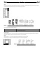
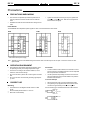
1
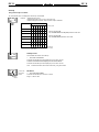
Digital Process Controller Series
E5K
Advanced Process Digital
Controllers
Field configurable output and option
boards
100 ms sampling (for analog input)
Advanced PID, or fuzzy self-tuning
Conforms to UL, CSA and CE standards
IP66/NEMA4X front panel
Remote set point (for E5EK and E5AK
only)
Set point ramp
Serial communications (RS-232C, and
RS-485; RS-422 for E5AK and E5EK
only) and transfer output (4 to 20 mA)
Front panel programming
Heat/cool or standard operation
Auto/manual and ON/OFF selections
Ordering Information
Order Control Output Boards and Option Boards separately below. Example: for a Relay Control Output, order the E53-R4R4 Output
Board in addition to the E5CK-AA1-500 Process Controller. For E5AK or E5EK, order an E53-R output module.
Note: You can mount only one Output Board and one Option Board to E5EK or E5CK.
Item
Description
Part number
Standard models
Base Unit with terminal cover
E5AK-AA2-500
E5EK-AA2-500
E5CK-AA1-500
E5CK-AA1-302
Position--proportional
Base Unit with terminal cover
24 AC/DC models
Base Unit with terminal cover
E5AK-PRR2-500
E5EK-PRR2-500
E5AK-AA2-500 AC/DC 24V
E5AK-PRR2-500 AC/DC 24V
E5EK-AA2-500 AC/DC 24V
E5EK-PRR2-500 AC/DC 24V
E5CK-AA1-500 AC/DC 24V
Note: 1. When using the heater burnout alarm function with a standard model, the Linear Output Module cannot be used for the control
outputs (heat). The Digital Controller provides transfer outputs at 4 to 20 mA for the PV and other values and control outputs at
4 to 20 mA for the current outputs.
2. Order Output and Option Boards separately.
3. E5EK-PRR2/E5AK-PRR2 controllers are supplied with relay output. The relay output is not compatible with any other module.
E5K
E5K
Ordering Information Table -- continued from previous page
Item
Description
Part number
Output Module (for
( E5AK and E5EK only)
y)
Relay
E53-R
SSR
E53-S
Pulse (NPN) 12 VDC
E53-Q
Pulse (NPN) 24 VDC
E53-Q3
Pulse (PNP) 24 VDC
E53-Q4
Linear (4 to 20 mA)
E53-C3
Linear (0 to 20 mA)
E53-C3D
Linear (0 to 10 V)
E53-V34
Linear (0 to 5 V)
E53-V35
Note: 1. The Digital Controller uses a dedicated, high-resolution Output Module. The E53-C Current Output Module for the E5 X cannot be used with the Digital Controller.
2. If the control period is less than 5 seconds, use solid state relay or pulse voltage.
Item
Description
Part number
Output Board (for
( E5CK only)
y)
Relay/Relay (See note.)
E53-R4R4
Pulse (NPN)/Relay
E53-Q4R4
Pulse (PNP)/Relay
E53-Q4HR4
Pulse (NPN)/Pulse (NPN)
E53-Q4Q4
Pulse (PNP)/Pulse (PNP)
E53-Q4HQ4H
Linear (4 to 20 mA)/Relay
E53-C4R4
Linear (0 to 20 mA)/Relay
E53-C4DR4
Linear (0 to 10 V)/Relay
E53-V44R4
Note: If the control period is less than 5 seconds, use solid state relay or pulse voltage.
Item
Description
Part number
Option Board (for
( E5AK and E5EK only)
y)
Communication (RS-232C)
E53-AK01
Communication (RS-422)
E53-AK02
Communication (RS-485)
E53-AK03
Event input
E53-AKB
Transfer output (4 to 20 mA)
E53-AKF
Note: 1. The E5AK allows a maximum of three Option Boards to be mounted. Refer to pages 25--26 for mounting combinations.
2. The E5EK and E5CK allows only one Option Board to be mounted.
Item
Description
Part number
Option Board (for
( E5CK only)
y)
Communication (RS-232C)
E53-CK01
Communication (RS-485)
E53-CK03
Event input
E53-CKB
Transfer output (4 to 20 mA)
E53-CKF
ACCESSORIES (ORDER SEPARATELY)
Item
Hole Diameter
Part number
Current Transformer ((for E5AK and E5EK
only)
l )
5.8 mm
E54-CT1
12.0 mm
E54-CT3
Note: CT is required when the heater burnout alarm function is used.
Item
Connectable Models
Part number
Terminal Cover
E5AK
E53-COV0809
E5EK
E53-COV08
E5CK
E53-COV07
E5K
E5K
INPUT TYPES (SELECTABLE WITH INPUT JUMPER CONNECTOR)
Platinum Resistance Thermometer (RTD’s)
Input (field selectable)
Range
g
JPt100
Pt100
°C
--199.9 to 650.0
--199.9 to 650.0
°F
--199.9 to 999.9
--199.9 to 999.9
0
1
Input setting number
Thermocouple
Input (field
selectable)
(see note)
Range
K1
K2
J1
J2
T
E
L1
L2
U
N
R
S
B
W
PL
°C
--200
to
1,300
0.0
to
500.0
--100
to
850
0.0
to
400.0
--199.9
to
400.0
0
to
600
--100
to
850
0.0
to
400.0
--199.9
to
400.0
--200
to
1,300
0
to
1,700
0
to
1,700
100
to
1,800
0
to
2,300
0
to
1,300
°F
--300
to
2,300
0.0
to
900.0
--100
to
1,500
0.0
to
750.0
--199.9
to
700.0
0
to
1,100
--100
to
1,500
0.0
to
750.0
--199.9
to
700.0
--300
to
2,300
0
to
3,000
0
to
3,000
300
to
3,200
0
to
4,100
0
to
2,300
2
3
4
5
6
7
8
9
10
11
12
13
14
15
16
Input setting
number
Note: 1. Setting number is factory-set to 2 (K1).
2. Thermocouple W is W/Re5-26 (tungsten rhenium 5, tungsten rhenium 26).
Current/Voltage
Input (field
(
selectable))
Input setting number
Current input
Voltage input
4 to 20 mA
0 to 20 mA
1 to 5 V2
0 to 5 V
0 to 10 V
17
18
19
20
21
Note: When a current/voltage input is selected, the decimal point is fully adjustable.
E5K
E5K
Specifications
RATINGS
Model number
E5 K Standard
E5 K
Supply voltage
100--240VAC, 50/60 Hz
24V AC/DC,
50/60Hz
Operating voltage range
Power consumption
Input
85% to 110% of rated supply voltage
85% to 110% of rated supply voltage
E5AK
16 VA
9VA, 6W
E5EK
15 VA
9VA, 6W
E5CK
10 VA (at 100 VAC)
14 VA (at 240 VAC)
6VA, 3.5W
Thermocouple
K, J, T, E, L, U, N, R, S, B, W, PL
Platinum resistance
thermometer (RTD)
JPt100, Pt100
Current input
4 to 20 mA, 0 to 20 mA
Voltage input
1 to 5 V, 0 to 5 V, 0 to 10 V
Mean Time Between Failure
Control output (See Note 1.)
Auxiliary
y output
24V AC/DC
15.4 years (135,000 hours
Relay
SPST, 250 VAC, 3 A (resistive load)
Mechanical life expectancy: 10,000,000 operations min.
Electrical life expectancy:
100,000 operations min.
Voltage
g
(P l )
(Pulse)
NPN
20 mA at 12/24 VDC (with short-circuit protection)
PNP
20 mA at 24 VDC (with short-circuit protection)
Linear voltage
0 to 10
VDC
Permissible load impedance: 1 kΩ min.
Resolution: Approximately 2600 steps
Linear current
4 to 20
mA
Permissible load impedance: 500 Ω max.
Resolution: Approximately 2600 steps
0 to 20
mA
Permissible load impedance: 500 Ω max.
Resolution: Approximately 2600 steps
E5AK
3 A at 250 VAC (resistive load)
E5EK
3 A at 250 VAC (resistive load)
E5CK
1A at 250 VAC (resistive load)
SPST-NO
Control method (See Note 2.)
ON/OFF, Advanced PID Control (with auto-tuning) or Self-tuning
Setting method
Digital setting using front panel keys or communications features
Indication method -- 7-seg. digital display and LEDs
E5AK: PV = 15 mm, SP = 10.5 mm
E5EK: PV = 14 mm, SP = 9.5 mm
E5CK: PV = 12 mm, SP = 8 mm
Potentiometer (Valve Positioning)
(for E5AK and E5EK only)
100 Ω to 2.5 kΩ
Event input
Contact input
No-contact
i
input
t
ON
1 kΩ max.
OFF
100 kΩ min.
ON
residual voltage: 1.5 V max.
OFF
leakage current: 0.1 mA max.
4 to 20 mA, permissible load impedance: 600 Ω max.,
resolution: Approximately 2600 steps
Transmission output
Remote SP input (for E5AK and E5EK only)
Current
input
4 to 20 mA (Input impedance: 150 Ω)
Current Transformer input (for E5AK and E5EK only)
Connect only an Omron Current Transformer (E54-CT1 or E54-CT3)
Other functions
Standard
Manual output, heating/cooling control, SP limiter, loop burnout alarm, SP
ramp, MV limiter, MV change rate limiter, input digital filter, input shift,
run/stop, protect functions
Option
Multiple SP, run/stop selection, transfer output functions, auto/manual
Communications (RS-232C, RS-422, or RS-485), Loop Break Alarm, and
Transfer Output.
Standards
UL
File No.: E68481
CSA
File No.: LR59623
CE
File No.: EN50081-2; EN50082-2; IEC 1010-1
Note: 1. All control outputs are insulated from the input circuit.
2. Fuzzy self-tuning is available only when using the Digital Controller in standard control operation with temperature input.
E5K
E5K
CHARACTERISTICS
Indication accuracy (See Note.)
Thermocouple:
(±0.3% of indication value or ±1°C, whichever is greater) ±1 digit max.
Platinum resistance thermometer:
(±0.2% of indication value or ±0.8°C, whichever is greater) ±1 digit max.
Analog input: ±0.2% (of indication value) ±1 digit max.
Hysteresis
0.01% to 99.99% FS (in units of 0.01% FS)
Proportional band (P)
0.1% to 999.9% FS (in units of 0.1% FS)
Integral (reset) time (I)
0 to 3,999 s (in units of 1 s)
Derivative (rate) time (D)
0 to 3,999 s (in units of 1 s)
Control period
1 to 99 s (in units of 1 s)
Manual reset value
0.0% to 100.0% (in units of 0.1%)
Alarm setting range
--1,999 to 9,999 or --199.9 or 999.9 (decimal point position dependent on input type)
Sampling period
Temperature
input
250 ms scan rate
Analog input
100 ms scan rate
Insulation resistance
200 MΩ min. (at 500 VDC)
Dielectric strength
Vibration resistance
Shock resistance
Ambient temperature
2,000 VAC, 50/60 Hz for 1 min between terminals of different polarities
Malfunction
10 to 55 Hz, 10 m/s2 (approx. 1G) for 10 min each in X, Y, and Z directions
Mechanical
10 to 55 Hz, 20 m/s2 (approx. 2G) for 2 hrs each in X, Y, and Z directions
Malfunction
200 m/s2 min. (approx. 20G), 3 times each in 6 directions
(100 m/s2 (approx. 10G) applied to the relay)
Mechanical
300 m/s2 min. (approx. 30G), 3 times each in 6 directions
Operating
--10°C to 55°C (14°F to 131°F ) with no icing; with 3-year warranty period: --10°C to 50°C
(14°F to 122°F )
Storage
--25°C to 65°C (--13°F to 149°F ) with no icing
Ambient humidity
Operating
35% to 85% RH
Enclosure ratings
g
Front panel
NEMA 4X for indoor use (equivalent to IP66)
Rear case
IEC standard IP20
Terminals
IEC standard IP00
Memory protection
Weight
g
EMC
Non-volatile memory (number of writings: 100,000 operations)
E5AK
Approx. 450 g
E5EK
Approx. 320 g
Mounting
bracket
Approx. 65 g
E5CK
Approx. 170 g
Adapter
Approx. 10 g
Emission Enclosure:
Emission AC Mains:
Immunity ESD:
Immunity RF-interference:
Immunity Conducted Disturbance:
Immunity Burst:
Standards -- Approvals
EN55011 Group 1 class A
EN55011 Group 1 class A
EN61000-4-2: 4 kV contact discharge (level 2)
8 kV air discharge (level 3)
ENV50140:
10 V/m (amplitude modulated,
80 MHz to 1 GHz) (level 3)
10 V/m (pulse modulated, 900
MHz)
ENV50141:
10 V (0.15 to 80 MHz) (level 3)
EN61000-4-4: 2 kV power-line (level 3)
2 kV I/O signal-line (level 4)
UL1092, CSA22.2 No. 14, CSA22.2 No. 1010-1
Conforms to EN50081-2, EN50082-2, EN61010-1 (IEC1010-1)
Conforms to VDE0106/part 100 (Finger Protection)
Note: Indication Accuracy -Of the K1, T, and N thermocouples at a temperature of -100°C or less: ±2°C ±1 digit maximum.
Of the U, L1, and L2 thermocouples at any temperature: ±2°C ±1 digit maximum.
Of the B thermocouple at a temperature of 400°C or less: unrestricted.
Of the R and S thermocouples at a temperature of 200°C or less: ±3°C ±1 digit maximum.
Of the W thermocouple at any temperature: ±0.3% of the indicated value or ±3°C, (whichever is greater) ±1 digit maximum.
Of the PL thermocouple at any temperature: ±0.3% or ±2°C, whichever is greater ±1 digit maximum.
E5K
E5K
OPTION BOARD RATINGS AND CHARACTERISTICS
Event inputs
Contact input:
ON: 1 kΩ max., OFF: 100 kΩ min.
No-contact input:
ON: residual voltage 1.5 V max., OFF: leakage current 0.1 mA max.
Communications
Interface
RS-232C and RS-485; RS-422 for E5AK and E5EK only
Transmission
method
Half-duplex
Synchronization
method
Start-stop synchronization (asynchronous method)
Baud rate
1.2/2.4/4.8/9.6/19.2 kbps
Transfer output
4 to 20 mA:
Permissible load impedance: E5AK and E5EK = 600 Ω max.
E5CK = 500 Ω max.
Resolution:
E5AK and E5EK = approx. 2,600 steps
E5CK = approx. 2,600 steps
RS-232C Peer-to-peer only; maximum cable length = 15 m (49.2 feet)
RS-422 and RS-485 32 controller maximum to host computer; maximum cable length = 500 m
(1640 feet)
CURRENT TRANSFORMER RATINGS
Max. continuous heater current
50 Amps
Dielectric strength
1,000 VAC (for 1 min)
Vibration resistance
50 Hz, 98 m/s2 (10G)
Weight
E54-CT1: approx. 11.5 g; E54-CT3: approx. 50 g
Accessories (E54-CT3 only)
Armature: 2; Plug: 2
HEATER BURNOUT ALARM
Max. heater current
Single-phase 50 A VAC (See Note 1.)
Heater current value display accuracy
±5% FS±1 digit max.
Heater burnout alarm setting range
0.1 to 49.9 A (in units of 0.1 A) (See Note 2.)
Min. detection ON time
190 ms (See Note 3.)
Note: 1. Use the K2CU-F
A- GS (with gate input terminals) for the detection of three-phase heater burnout.
2. The heater burnout alarm is always OFF if the alarm is set to 0.0 A and always ON if the alarm is set to 50.0 A.
3. No heater burnout detection or heater current value measurement is possible if the control output (heat) is ON for less than
190 ms.
E5K
E5K
Nomenclature
E5AK
Operation Indicators
No. 1 display
Operation
Indicators
No. 2 display
• OUT1
Lit when control output 1 turns ON.
• OUT2
Lit when control output 2 turns ON.
• SUB1
A/M Key
Display Key
Lit when the output function assigned
to auxiliary output 1 turns ON.
Up Key/Down Key
• SUB2 (for E5AK and E5EK only)
Lit when the output function assigned
to auxiliary output 2 turns ON.
• MANU
E5EK
Lit when the manual operation mode
is being used.
• STOP
Lit when control operation has been
stopped.
No. 1 display
No. 2 display
Operation Indicators
Lit during remote communications
operation.
• AT
Flashes during auto-tuning.
Auto-tuning is completed when this
LED stops flashing.
Display Key
A/M Key
• RMT
Up Key/Down Key
• RSP (for E5AK and E5EK only)
Lit during remote SP operation.
• Bar Graph (for E5AK only)
E5CK
No. 1 display
Operation
Indicators
A/M Key
Display Key
No. 2 display
On a standard model (E5AK-AA2), this
bar graph indicates the manipulated
variable (heat) in 10% increments per
single segment. On a position-proportional model (E5AK-PRR2), this bar
graph indicates the valve opening in
10% increments per single segment.
No. 1 Display
Displays the process value or parameter
symbols.
No. 2 Display
Displays the set point, set point during SP
ramp, manipulated variable, or parameter
settings.
Up Key/Down Key
A/M Key
Press to select the auto operation or manual operation.
E5CK-302
Up Key/Down Key
Press to increase or decrease the value on
the No.2 display.
No. 1 display
Operation
Indicators
AT Key
Display Key
No. 2 display
Display Key
Press quickly (for less than 1 s) to shift the
display to the next parameter. When this key
is pressed for 1 s or more, the menu screen
will be displayed in any case.
• AT
Up Key/Down Key
Press key for automatic tuning.
• A/M
This feature is located in level one.
(Replaced AT feature in level one).
E5K
E5K
Operation
OPERATING PARAMETERS
Mode Selection
Press the Display Key for 1 sec. min. to switch to modes other than
the manual or protect mode.
The figure below (Menu Display) shows all modes in the order that
they are displayed. Some parameters are not displayed, depending
on the protect mode setting and the option boards used.
Menu Display
To Access Protect Mode
Press and hold the A/M Key and the Display Key for more than
1 second.
To Return to the Main PV/SP Display from the Protect Mode
Press and hold the A/M Key and the Display Key for more than
1 second.
To Access Manual Mode
Press and hold the A/M Key for more than 1 second.
1 second min.
Level 0 mode
To switch parameters within a mode, use the Display Key.
Press the display key for less than one second to move between
parameters.
Level 1 mode
Note:
1 second min.
1. In Level 0 mode, Level 1 mode, and Level 2 mode:
The controller will maintain control of the process.
Level 2 mode
Setup mode
Expansion mode
2. In Setup mode, Expansion mode, Option mode,
and Calibration mode: Control of the process is not
maintained. The outputs are inactive.
Option mode
3. Option Mode will be accessible only when an option
board is installed in the controller.
Calibration mode
PARAMETERS AND MENUS -- FOR SETTING THE CONTROLLER
Protect Mode
Limits use of the menu and A/M Keys.
The protect function prevents unwanted modification of parameters and can also be used to prevent switching between
the auto and manual operation.
Manual Mode
Sets the controller to manual operation mode.
You can only manually adjust the manipulated variable (MV) in this mode.
Level 0 Mode
For normal operation.
Change: the set point during operation, and start or stop Controller operation; and, (only in this mode) monitor the
process value, ramp SP, and manipulated variable.
Level 1 Mode
For adjusting primary control parameters.
Execute: AT (auto-tuning); set alarm values; set the control period; and, set PID parameters.
Level 2 Mode
For adjusting secondary control parameters.
Set parameters for: limiting the manipulated variable and set point; switch between the remote and local modes; set the
loop break alarm (LBA), alarm hysteresis, and the digital filter value of inputs.
Setup Mode
For setting the basic specifications.
Set parameters for: input type, scaling, output assignments and direct/reverse operation.
Expansion Mode
For setting expanded functions.
Set: ST (self-tuning), SP setting limiter. Select: advanced PID or ON/OFF control. Specify the standby sequence
resetting method. Initialize parameters; and, set the time for automatic return to the monitoring display.
Option Mode
For setting option functions.
Set: the communications conditions; transfer: output and event input parameters to match the type of Option Board
installed in the Controller. This mode will be accessible only when an option board is installed in the controller.
Calibration Mode For calibrating inputs and transfer output.
Calibrate the selected input type. Transfer output can be calibrated only when the Communications Unit (E53-CKF) has
been installed in the Controller.
E5K
E5K
PARAMETERS DEFINITIONS
Refer to your User’s Manual for each parameter and the calibration mode in detail.
Level 0 Mode for E5AK and E5EK
PV/SV
The process value is displayed on the No.1 display and the set point is displayed
on the No.2 display. When the multi-SP function is in use, the value of the current
set point (SP0 or SPD is displayed).
Set Point During SP Ramp
Monitors the set point when the SP ramp function is used.
For E5KPRR2
Manipulated Variable (MV) Monitor for Heat
Monitors the manipulated variable (MV) for the heating output.
Valve Opening Monitor
Displays the valve position in percentage format.
Open = 100%
Closed = 0%
Manipulated Variable (MV) Monitor for Cool
When the Controller is in heating and cooling control operation, use this
display to monitor the manipulated variable of the cooling output.
Run/Stop
Places the controller in RUN mode or in STOP mode.
Level 0 Mode for E5CK
PV/SV
The process value is displayed on the No.1 display and the set point is displayed on the No.2 display.
When the multi-SP function is in use, the value of the current set point (SP0 or SP1 is displayed).
Set Point During SP Ramp
Monitors the set point when the SP ramp function is used.
Manipulated Variable (MV) Monitor for Heat
Monitors the manipulated variable (MV) for the heating output.
Manipulated Variable (MV) Monitor for Cool
When the Controller is in heating and cooling control operation, use this display to monitor the manipulated
variable of the cooling output.
Run/Stop
Places the controller in RUN mode or in STOP mode.
E5K
E5K
Security
Using the Security Level Table:
Any mode marked with an X is displayed in the Security Level indicated.
Example:
Selecting Security Level 2:
Displays these modes: Level 0, Level 1 and Level 2 only.
Does NOT display these modes: Setup, Expansion, Option, Calibration
Mode
Set value
0
1 2
3
Calibration
x
Option
x
x
Expansion
x
x
Setup
x
x
Level 2
x
x
x
Level 1
x
x
x
x
x
x
x
x
Level 0
4
5
6
⇐ Security Level
When the set value is 5:
Only the PV/SP monitor and set point parameter can be used.
When the set value is 6:
Only the PV/SP monitor parameter can be used.
x
x
⇑ Lowest
Security Level
(first column)
⇑ Highest Security
Level (last column)
A/M Key Protect
This invalidates the function of the A/M Key.
•
To Access Protect Mode
Press and hold the A/M Key and the Display Key for more than 1 second.
To Return to the Main PV/SP Display from the Protect Mode
Press and hold the A/M Key and the Display Key for more than 1 second.
Note:
MANU
indicator
Process value
Manipulated
variable
For E5CK-302 models, this is done the same way, using the AT button.
MV Manual
•
To Access Manual Mode
Press and hold the A/M Key for more than 1 second.
Range = --105% to 105%
E5K
E5K
Level 1 Mode
AT Execute/Cancel
Starts the Auto-tune function or cancels an active auto-tune. When an active auto-tune is cancelled, the original
PID constants will be used again.
AT-1 = Limited MV change during Autotuning (±40% max.)
AT-2 = Full MV change during Autotuning (±100% max.)
Note:
E5AK and E5EK can have up to 4 set points or 4 alarms
Set Point 0
Set Point 1
Alarm Value 1
Default set point when used with multi-SP function. This set point is active when the Event input is OFF.
Note:
E5AK and E5EK can have up to 4 set points or 4 alarms
Used only with multi-SP function. This set point is active when the Event input is ON.
This parameter is available only if an Event Input Option Board is installed.
Available only when Control Output 2 is not used as a control output. This setting determines what the Alarm 1 set
point will be.
Alarm Value 2
Available only when the alarm output function of the Controller is selected. This setting determines what the Alarm
2 set point will be. This alarm can be programmed to work on Control Output 2 or the SUB-1 output (user-selectable). Factory Default = Control Output 2.
Note: Alarm Value 3 is available only when SUB-1 or Control Output No. 1 is selected as AL-3.
Proportional Band
Range = 0.1% to 999.9%
Integral Time
Range = 0 to 3999 seconds
Derivative Time
Range = 0 to 3999 seconds
See Note at right.
Note:
For Valve Positioning Models E5 K--PRR2, all
subsequent parameters (those after Derivative Time)
listed in Level 1 Mode are not available. See Level 1
Valve Positioning model (provided on the following
page).
Cooling Coefficient
Used when the Controller is in heat/cool control. This setting describes the ratio between the heating proportional
band and the cooling proportional band.
Dead Band
Manual Reset Value
Used when the Controller is in heating and cooling control. This setting determines the amount of overlap or dead
band present in a heat/cool configuration. Range = -19.99 → 99.99.
Negative values = overlap band. Positive values = Dead band.
Available ONLY when the integral time parameter of the Controller in standard control is set to 0.
The Controller must be in Standard or Advanced PID control and self-tune must be set to off.
Hysteresis (Heat)
Available when the Controller is in ON/OFF control.
If PID control selected, this value will not appear on the menu.
Range = 0.01 to 99.99 FS. Default = 0.10.
Hysteresis (Cool)
Available when the Controller is in ON/OFF control in heating and cooling control.
Range = 0.01 to 99.99 FS. Default = 0.10.
Control Period (Heat)
Available only when the Controller has a relay or voltage output, or is in advanced PID control.
Range = 1 to 99 s. Default = 20 s.
Control Period (Cool)
Available when the Controller has a relay or voltage output, or is in advanced PID control in heating and cooling
control.
Range = 1 to 99 s. Default = 20 s.
Note:
This level 1 Mode ends here for the E5CK models only. For all other E5 K models in this data sheet,
continue with the next page.
E5K
E5K
Level 1 Valve Positioning Model (for E5AK and E5EK only)
Position Proportional Dead Band
Heater Current Monitor
For valve positioning units only.
Used to adjust the dead band for a valve; displayed in percentage format.
Range = 0.1--10
Default = 2.0
Available when the heater burnout alarm is assigned.
Heater Burnout Detection
Available when the heater burnout alarm is assigned.
Activates the Heater Burnout Alarm when the heater current falls
below the set value.
Range = 0.0--50.0A
Default = 0.0
E5K
E5K
Level 2 Mode
Remote/Local
Used for the communications function. Only accessible when communication option boards are installed.
Determines whether the user will program the unit by the key pads on the face plate (local), by a computer, or PLC (remote).
Default = local.
SP Ramp Time Unit
Determines what unit of time to use on a set point ramp: minutes or hours. Self-tune must be set to OFF
Default = minutes.
SP Ramp Set Value
Determines the maximum allowable degrees of change per Time Unit.
Example: SP Ramp Time Unit = minute
SP0 = 100F
SP Ramp Set Value = 10
SP1 = 150F
It will take 5 minutes to ramp up to 150F from 100F.
Default = 0.
LBA Detection Time
Available only when the LBA (loop break alarm) function of the Controller is selected.
This parameter is automatically set by Auto--tuning. Determines how long it will take the controller to detect a loop break.
Range = 0 -- 9999 sec.
Default = 0
Manipulated Variable (MV) at Stop
Determines what percentage of Manipulated Variable (MV) will be when control has been stopped.
Default = 0%
Range = -5 to 105% for standard control; -105 to 105% for heat/cool control.
MV at PV Error
MV Upper Limit
Determines what percentage of Manipulated Variable (MV) will be when an input error has been detected.
Default = 0%
Range = -5 to 105% for standard control; -105 to 105% for heat/cool control.
Stops the MV from going higher than the set value. Default = 105%
MV Lower Limit
Stops the MV from going lower than the set value.
Default (heat only) = --5%
Default (heat/cool) = --105%
Default (cool only) = --105%
MV Change Rate Limit
Limits how fast the MV can change in % of FS per second.
Default = 0%
Range = 0 -- 100%
Input Digital Filter
Sets the time constant for the digital filter.
Range = 0 to 9999 sec.
Default = 0
Alarm 1 Hysteresis
Available only when the Controller has an alarm output.
Range = 0 to 9999 sec.
Default = 0.2
Alarm 2 Hysteresis
Available only when the Controller has an alarm output.
Range = 0 to 9999 sec.
Default = 0.2
Alarm 3 Hysteresis (Note: An example of this display is not shown here.)
Available only when the Controller has an alarm output.
Range = 0 to 9999 sec.
Default = 0.2
Input Shift Upper Limit
Available if the input type connected to the Controller is a thermocouple or platinum RTD.
Range = --199.9 to 999.9 °C/°F; default = 0 to 0 °C/°F
Input Shift Lower Limit
Available if the input type connected to the Controller is a thermocouple or platinum resistance
thermometer.
Range = --199.9 to 999.9 °C/°F; default = 0 to 0 °C/°F
E5K
E5K
Setup Mode
Input Type
Sets the input type connected to terminals 6 through 8.
Note: Set input jumper to current, voltage, or temperature setting before changing input type.
Default = 2 (K1 type thermocouple)
Scaling Upper Limit
Used if the input type connected to the Controller is an analog input (voltage or current input).
Range = 1 to 9999
Default = 100
Scaling Lower Limit
Used if the input type connected to the Controller is an analog input (voltage or current input).
Range = --1999 to --1
Default = 0
Decimal Point
Used only if the input type connected to the Controller is an analog input (voltage or current input).
Range = 0 to 3
Default = 0
°C/°F Selection
Used if the input type connected to the Controller is a temperature input (thermocouple or platinum resistance
thermometer).
Default = °C
Parameter Initialize
Returns the controller to Factory Default Settings.
Control Output 1 Assignment
Assigns the Controller to have one of the following output functions: heating control, cooling control, alarm 1,
alarm 2, alarm 3, and LBA (loop break alarm).
Default = heat
Control Output 2 Assignment
Auxiliary Output 1 Assignment
Assigns the Controller to have one of the following output functions: heating control, cooling control, alarm 1,
alarm 2, alarm 3, and LBA (loop break alarm).
Default = Alarm 1
Enables the Controller to have one of the following outputs: alarm 1, alarm 2, alarm 3, LBA (loop break alarm)
Default = Alarm 2
Note: The following parameters are available only when the controller has an alarm output. (See the table on the
Expansion Mode table.
Alarm 1 Type
Provides a choice of 11 different alarm operations.
Default = 2 (See Alarm Summary Table for Alarm types available.)
Alarm 1 Open in Alarm
Synchronizes the alarm LED with the operation of the alarm. If the alarm is operating as a normally closed relay
(open in alarm condition), this parameter should be set to ’Open in Alarm’. If the alarm is operating as a normally
open relay (close in alarm condition), this parameter should be set to ‘Close in Alarm’.
Alarm 2 Type
Provides a choice of 11 different alarm operations.
Default = 2 (See Alarm Summary Table for Alarm types available.)
Alarm 3 Type Note: An example of this display is not shown here.
OPEN W/Alarm
Alarm 2 Open in Alarm
Direct/Reverse Operation
Synchronizes the alarm LED with the operation of the alarm. If the alarm is operating as a normally closed relay
(open in alarm condition), this parameter should be set to ’Open in Alarm’. If the alarm is operating as a normally
open relay (close in alarm condition), this parameter should be set to ‘Close in Alarm’.
Choose between direct (cooling) or reverse (heating) control action.
Default = reverse (heating).
Direct (cooling) = MV increases with decreasing PV.
Reverse (heating) = MV increases with increasing PV.
E5K
E5K
Selecting a Control Method
When selecting a control method, refer to the following table for correct parameter setting.
Control method
Control output 1 assignment
Control output 2 assignment
Operation
Heat
Control output (heat)
---
Reverse
Cool
Control output (heat)
---
Direct
Heat/Cool
Control output (heat)
Control output (cool)
Reverse
Heat/Cool
Control output (cool)
Control output (heat)
Direct
CLOSE IN ALARM/OPEN IN ALARM
If the alarm is operating as a normally closed relay (open in alarm condition), this parameter should be set to ‘Open in Alarm’. If the alarm
is operating as a normally open relay (close in alarm condition), this parameter should be set to ‘Close in Alarm’.
Condition
Alarm
Output LED
Close in alarm (N.O.)
(
)
ON
Lit
OFF
Not lit
ON
Lit
OFF
Not lit
Open in alarm (N.C.)
(
)
Factory setting is “close in alarm” [ ].
E5K
E5K
Expansion Mode
SP Setting Upper Limit
Stops the set point from going higher than the SP setting upper limit.
Default = 1300
This setting has no effect on the input scaling values.
SP Setting Lower Limit
Stops the set point from going any lower than the SP setting lower limit
Default = -200
This setting has no effect on the input scaling values.
PID/ON/OFF
Selects the type of control method for the controller to use.
Default = PID
Adaptive Tuning (Self Tuning)
Only available if the Controller in standard control or advanced PID control has a temperature input.
Default = OFF. If ON is selected, the controller will use fuzzy logic to self tune the PID values for optimum control.
PID values will not be seen when ST (Self Tune) is on.
ST Stable Range
Only available if the Controller is in standard control or advanced PID control with the Self Tune (ST) set to ON.
α
Only available if the Controller is in advanced PID control with the ST set to OFF.
This setting allows tailoring of the PID algorithm to emphasize control or fast response.
Default = 0.65
Fast Response = 0.0 → 0.65
Stability Emphasis = 0.65→ 1
AT Calculated Gain
Alarm Standby Sequence Reset Method
Allows the controller to focus the auto-tune on increased response or more stability.
Range = 0.1 (fast response) to 10 (increase stability).
Available if the Controller is in advanced PID control with the ST set to OFF.
Default = 1.0
Used with alarm settings to have a stand-by sequence applied to the alarm.
Default = 0
Automatic Return of Display Mode
Automatically returns the display of the controller to Level 0 PV/SP display after the set amount of time has
elapsed if no buttons on the face plate have been used.
Applies only in Levels 0 through 2. Default = 0. Range = 0 to 99 sec.
AT Hysteresis
LBA Detection Width
Only available if the Controller is in advanced PID control with the ST set to OFF.
Default = 0.2% FS; Range = 0.1 to 9.9% FS
Only available only when the LBA (Loop Break Alarm) function of the Controller is selected.
Range 0.0 → 999.9% FS
Default = 0.2
E5K
E5K
Option Mode -- ONLY Visible if an Option Board is Installed
E5K
Multi-SP Function
Specifies the number of set points that will be used. Must be set to one to use SP Ramp feature.
Available for the event input function. Default = 0
Event Input Assignment 1
Available for the event input function. If multi-SP is set to 0, this parameter assigns event input
function as: Run/Stop, Auto/Manual, or Protect Function. Default = Stop.
E5AK and E5EK only
Event Input Assignment 2
Available for the event input function.
Event Input Assignment 3
Available for the event input function.
Event Input Assignment 4
Available for the event input function.
COMMUNICATIONS FUNCTION
Communications selections are ONLY available if a communications board is installed.
Communication Stop Bit
Displayed when the communications function is in use.
Range = 1 to 2
Default = 2
Communication Data Length
Displayed when the communications function is in use.
Range = 7 to 8
Default = 7
!
Communication Parity
Displayed when the communications function is in use.
Range = None, Even, Odd
Default = Even
Communication Baud Rate
(continued on next page)
Displayed when the communications function is in use.
Range = 1.2, 2.4, 4.8, 9.6, 19.2 k baud
Default = 9.6
Communication Unit No.
Displayed when the communications function is in use.
Range = 0 — 99
Default = 0
E5K
E5K
Option Mode -- ONLY Visible if an Option Board is Installed, continued
Transfer output selections are ONLY available if a transfer
board is installed.
TRANSFER OUTPUT SECTION
Transfer Output Type
Set when the transfer output function is in use.
Determines which function the transfer output will re-transmit as a 4-20mA signal: SP, PV, SP
Ramp, MV
Transfer Output Upper Limit
Set when the transfer output function is in use.
Stops the transfer output from going higher than the Set Value.
Transfer Output Lower Limit
Set when the transfer output function is in use.
Stops the transfer output from going lower than the Set Value.
REMOTE SET POINT FUNCTION
Remote set point function is available on all E5AK/E5EK
models, with or without an option board installed.
HBA Latch
"
"
Makes the heater burnout alarm remain activated when triggered. It must be reset
manually.
Motor Calibration
Determines how long it takes a fully closed proportional valve to fully open.
Travel time
"
"
The amount of time it takes to determine the motor calibration parameter.
Range = 1--999 sec.
Default = 30 sec.
PV Dead Band
Determines the size of the dead band around the process variable in which the valve
will take no control action.
Range = 0--9999
Default = 0
Remote SP Enable
Enables the controller to use a remote setpoint.
Default = off
Remote SP Upper Limit (Available when the remote SP is enable)
Stops the RSP from going any higher than the set value.
Default = 1300
Remote SP Lower Limit (Available when the remote SP is enable)
Stops the RSP from going any lower than the set valve.
Default = --200
SP tracking (Available when the remote SP is enable)
Allows a smooth transition between a RSP and a local SP when enabled. When on,
the LSP will become the RSP that was being used immediately before switching.
E5K
E5K
ALARM MODE SELECTORS
Alarm outputs are available if they are allocated as outputs. Factory setting is “2: Upper-limit alarm (deviation).”
Setting
number
1
Alarm types
Alarm output
When X is positive
Upper- and lower-limit alarm (deviation)
X
ON
OFF
2
Upper-limit alarm (deviation)
When X is negative
X
Always ON
SP
X
ON
ON
OFF
OFF
SP
3
Lower-limit alarm (deviation)
X
ON
X
SP
X
ON
OFF
OFF
SP
4
Upper- and lower-limit range alarm (deviation)
X
ON
OFF
5
6
Upper- and lower-limit alarm with standby sequence (deviation)
Upper-limit alarm with standby sequence
(deviation)
SP
X
Always OFF
X
Always OFF
SP
X
ON
OFF
SP
X
ON
ON
OFF
OFF
SP
7
Lower-limit alarm with standby sequence
(deviation)
X
ON
Absolute-value upper-limit alarm
OFF
X
ON
ON
OFF
Absolute-value lower-limit alarm
ON
OFF
Absolute-value upper-limit alarm with standby
sequence
X
ON
ON
OFF
Absolute-value lower-limit alarm with standby
sequence
X
0
X
ON
0
OFF
0
11
X
OFF
0
10
SP
X
0
X
ON
X
OFF
0
9
SP
ON
OFF
SP
8
X
ON
OFF
OFF
0
X
0
Note: 1. A deviation is defined as deviation from SP.
2. An absolute alarm is defined as a fixed value X with reference to 0.
3. Standby sequence is defined as having the alarm outputs inactive until SP is reached on the initial power up of the Controller.
After SP has been reached, alarms will function normally.
Deviation Alarm
Absolute Alarm
If the alarm mode selector is set to a number between 1 to 7,
alarm values are set to the width deviated from the set point as
shown in the following illustration.
If the alarm mode selector is set to 8 or 9, alarm values are set to
the absolute value based on 0°C/°F as shown in the following
illustration.
Alarm value = 10°C/°F
110°C/°F
Set point (SP)
100°C/°F
Alarm value = 328°C/°F
328°C/°F
Set point (SP)
325°C/°F
E5K
E5K
HOW TO USE THE ERROR DISPLAY
When an error has occurred, the No.1 display alternately indicates error codes together with the current display item.
This section describes how to check error codes on the display, and the actions that must be taken to remedy the problem.
Input Error
Meaning
Input is in error.
Action
Check the wiring of inputs, disconnections, and shorts, and check the input type and the input type jumper connector.
Operation at Error For control output functions, output the manipulated variable matched to the setting of the “MV at PV error” parameter
(level 2 mode). Alarm output functions are activated when the upper limit is exceeded.
Memory Error
Meaning
Internal memory operation is in error
Action
First, turn the power OFF then back ON again. If the display remains the same, the E5AK/E5EK Controller must be
repaired. If the display is restored to normal, the probable cause may be external noise affecting the control system. Check
for external noise.
Operation at Error Control output functions turn OFF (2 mA max. at 4 to 20 mA output, and output equivalent to 0% in case of other outputs).
Alarm output functions turn OFF.
A/D Converter Error
Meaning
Internal circuits are in error.
Action
First, turn the power OFF then back ON again. If the display remains the same, the E5AK/E5EK Controller must be
repaired. If the display is restored to normal, the probable cause may be external noise affecting the control system. Check
for external noise.
Operation at Error Control output functions turn OFF (2 mA max. at 4 to 20 mA output, and output equivalent to 0% in case of other outputs).
Alarm output functions turn OFF.
Calibration Data Error
This error is output only during temperature input and is displayed for two seconds when the power is turned ON.
Meaning
Calibration data is in error.
Action
Must repair.
Operation at Error Both control output functions and alarm output functions are active. However, note that the readout accuracy is not
assured.
Display Range Over
Meaning
Though not an error, this is displayed when the process value exceeds the display range when the control range (setting
range ±10%) is larger than the display range (--1999 to 9999).
• When less than “--1999”
• When greater than “9999”
Operation
Control continues, allowing normal operation.
E5K
E5K
FUZZY SELF-TUNING
Fuzzy self-tuning is a function that enables the E5 K to calculate
the most suitable PID constants for the control output.
Features
•
•
The E5 K determines by itself when to perform fuzzy selftuning.
During fuzzy self-tuning, the E5 K does not output any signal that disturbs the temperature or output value.
Fuzzy Self-tuning Function
The fuzzy self-tuning function has three modes.
•
•
•
In SRT (step response tuning) mode, the PID constants are
tuned using a step response method at the time the set point
is changed.
In DT (disturbance tuning) mode, the PID constants are
amended so that the controlled temperature will be within the
target range set in advance when there is external disturbance.
In HT (hunting tuning) mode, when hunting occurs, the PID
constants are amended to suppress the hunting.
Note:
You must turn ON the power supply to the LOAD
either before or simultaneously with the start of
Temperature Controller operation.
Dead time will be measured from the time the
Temperature Controller starts operating. If a load,
such as a heater, is turned on after the Temperature
Controller is turned on, dead time longer than the
actual value will be measured, and inappropriate PID
constants will be obtained.
If an extremely large amount of dead time is
measured, the control amount will be set to 0% for a
short period of time before being returned to 100%,
and the constants will then be retuned. Retuning is
performed only for large amounts of dead time, so
be sure to follow the precaution given above when
starting operation.
Startup Conditions of SRT
Stable Temperature Status
SRT will start if conditions 1 to 5 are satisfied when the set point
is changed, or the E5 K is turned on.
If the temperature is within the stable range for a specified period,
the temperature is considered stable.
1. The new set point is different from the set point used at the
time SRT was last executed.
2. The difference between the new set point and the last set
point is larger than the value obtained from the calculation:
present proportional band value (P) x approximately 1.27+4.
Temperature
Slope (R)
P x 1.27
Note: When the E5 K is turned on, the difference between the
process value and set point is regarded as Deviation.
3. The temperature is stable before changing the set point, or
the temperature is balanced while the E5 K is turned on
before any output is obtained.
4. The set point is changed in the direction that the controlled
amount increases (i.e., the control amount is in the upper
direction at the time of reverse operation and in the lower
direction at the time of normal operation).
5. No SRT has been executed with the current set point.
Stable range
SP
Completion of SRT
In the following cases, SRT will not be executed accurately.
Therefore the E5 K must be tuned in DT or HT mode.
1. The maximum temperature slope (R) is not obtained before
the process value reaches the value obtained from the calculation: present proportional band value (P) x approximately
1.27 (i.e., the maximum temperature slope (R) is not obtained before the SRT is finished). If the proportional band,
obtained before SRT is finished, is larger than the previous
proportional band, however, the PID constants will be renewed, so their values will be more accurate.
2. The set point is changed during SRT, and the SRT completion conditions are satisfied; and, no PID constant will be
renewed.
Time
Balanced Status
If the process value is within the stable range for 60 s when there
is no output, the the temperature is considered balanced.
E5K
E5K
Startup Conditions of DT
Startup Conditions of HT
1. DT will start if the temperature that has been stable varies
due to external disturbance and the deflection of the temperature exceeds the stable range, and then the temperature
becomes stable, provided that the number of maximum temperature values is less than four.
2. DT will start if the set point is changed under the condition
that SRT does not start and the temperature becomes stable,
provided that the number of maximum temperature values is
less than four.
If there are four or more maximum temperature values, HT
will start.
HT will be ON when there is hunting with four or more maximum
temperature values (extreme values) while SRT is not being
executed.
Extreme value 2
Extreme value 2
Extreme value 4
Temperature
SP
Extreme
value 1
Extreme
value 3
Set point change
Temperature
Time
SP
Extreme value 1
Balanced Status
If the process value is within the stable range for 60 s when there
is no output, it is deemed that the the temperature is balanced.
Note: In specific applications where temperature varies periodically due to disturbance, internal parameters need to be
adjusted. For details, refer to your User‘s Manual.
E5K
E5K
Dimensions
Unit: mm (inch)
E5AK
13.5
(0.53)
110 min.
91 (3.58) x 91 (3.58)
112 (4.41)
96 (3.78) x 96 (3.78)
Panel Cutouts
100 (3.94)
120 min.
Note: 1. Recommended panel thickness is 1 to 8 mm.
2. Maintain the specified vertical and horizontal mounting space between each Unit.
Units must not be closely mounted vertically or horizontally.
E5EK
13.5
(0.53)
Panel Cutouts
60 min.
100 (3.94)
91 (3.58)
112 (4.41)
48 (1.89)
Note:
120 min.
1. Recommended panel thickness is 1 to 8 mm.
2. Maintain the specified vertical and horizontal mounting space between each Unit.
Units must not be closely mounted vertically or horizontally.
E5CK
13
(0.51)
100 (3.94)
48 (1.89)
58 (2.28)
53 (2.09) x 53 (2.09)
Panel Cutouts
44.8 (1.76) x 44.8 (1.76)
65 min.
Note:
60 min.
+0.6
45 0
+0.6
45 0
1. Recommended panel thickness is 1 to 5 mm.
2. Maintain the specified vertical and horizontal mounting space between each Unit.
Units must not be closely mounted, either vertically or horizontally.
E5K
E5K
E5CK-302
The E5CK-302 model has the same dimension and cutouts as the E5CK.
ACCESSORIES (ORDER SEPARATELY)
Terminal Cover for E5EK
Terminal Cover for E5AK
E53-COV0809
43.2 (1.70)
3
3
3
1.5
3
1.5
89 (3.50)
89 (3.50)
43.2 (1.70)
E53-COV08
89 (3.50)
22.05
(0.87)
Terminal Cover for E5CK
E53-COV07
44.3
(1.74)
44.3
(1.74)
Current Transformer (E5AK and E5EK only)
E54-CT1
E54-CT3
21 (0.83)
15 (0.59)
5.8 dia.
(0.23)
2.36 dia.
2.8
(0.11)
30
(1.18)
7.5 (0.30)
3
25
(0.98) (0.12)
12 dia.
(0.47)
40 (1.57)
x 40 (1.57)
40 (1.57)
Two, M3 (depth: 4)
10
(0.39)
15
30 (1.18)
30
(1.18)
E5K
E5K
Installation
REMOVE CONTROLLER FROM REAR HOUSING
E5AK and E5EK
To pull out the internal mechanism from the housing, use a Phillips screwdriver matching the screw on the lower part of the front panel.
1. Turn the screw counterclockwise while pressing the hook on the upper part of the front panel.
2. Carefully pull out the internal mechanism while holding the left and right sides of the front panel.
Hook
E5CK
Terminals
First, while pressing the hooks on the left and right sides of the
front panel, pull the internal mechanism from the housing.
Output
Board
Housing (case)
Input Type
Jumper Connector
Option
Board
Front Panel
E5K
E5K
SETTINGS
Note: Always turn off the power supply to the Digital Controller before changing any switch settings.
On a standard model, set up the Output Modules for control outputs 1 and 2 before mounting the Controller.
On a position-proportional model, the Relay Output Module is already set. Do not change that set-up parameter. Do not replace with
other Output Modules.
Setting Up and Removing the Output Module
Setting Up the Output Module
Removing the Output Module
When setting up the Output Modules, pull out the internal
mechanism from the housing and insert the Output Modules
into the sockets for control outputs 1 and 2.
To replace the Output Module, use a flat-blade screwdriver to
push up the Output Module.
Setting Up the Option/Output Board
E5AK
1. Remove the Power Board and Option Boards in the order
shown in the following diagram.
Power
Board
2. Insert the Option Boards into the sockets for options 1 to 3.
The following diagram shows the relationship between the
Option Boards and mounting positions.
Option
Board
3. Mount the option boards and the power board in the
order shown.
E5K
E5K
E5EK
1. Remove the Power Board in the order shown in the following
diagram.
2. Insert the Option Board into the socket for option 1. The
following diagram shows the relationship between the
Option Board and mounting position.
Power
Board
3. Mount the option boards and the power board in the order
shown.
E5CK
Set up the Option Board
1. Two rectangular holes are provided on the Power Board
(right side of Controller). Fit the two protrusions of the
output board into these two holes.
2. With the output board fitted into the Power Board, fit the
output board into the connector on the control board (left
side of Controller).
1. Place the bottom of the Controller facing up, fit the board
horizontally into the connector on the power board (right
side of controller).
2. With the Power Board connected, fit the board vertically
into the connector on the control board (left side of
Controller).
1
1
2
2
E5K
E5K
MOUNTING CONTROLLER
E5AK and E5EK
1. Insert the controller into the panel’s mounting hole at the
position shown in the figure below.
2. Fit the mounting bracket (accessory) into the mounting
slots on the top and bottom of the rear case.
E5CK
1. Insert the E5CK Controller into the cutout on the panel,
as shown in the figure here.
2. Push the adapter along the Controller body from the terminals up to the panel, and fasten temporarily.
3. Tighten the two mounting screws on the adapter. When
tightening screws, tighten the two screws alternately
keeping the torque to approximately 0.29 to 0.39 N m,
or 3 to 4 kgf cm.
Adapter
Panel
Watertight gasket
3. Tighten the mounting bracket screws on the upper and lower
parts in small increments alternately and equally until the
ratchet start to slide.
E5K
E5K
MOUNTING TERMINAL COVER
E5AK and E5EK
E5CK
1. Fasten the terminals covers as follows by using the plastic
pins. Plastic pins are provided with the terminal covers.
1. The E5CK-AA1-500 Controller is provided with a Terminal
Cover (E53-COV07). Fasten the Terminal Cover as follows by using the plastic pin.
E5CK
E53--COV07
WIRING TERMINALS FOR E5AK
E5AK Terminal Arrangement
Wiring
In the following wiring diagrams, the left side of the terminal
numbers indicate the inside of the Controller.
AC100--240V
50/60 Hz
OPTION
2
OPTION
1
Power Supply
Input power to terminal numbers 9 and 10. Power specifications
are as follows: 100 to 240 VAC, 50/60 Hz, approx. 16 VA
OPTION
3
SENSOR
INPUT
TRSF:
EV1 to 4:
PTMR:
RSP:
Transfer output
Event input
Potentiometer
Remote SP input
E5K
E5K
WIRING TERMINALS FOR E5EK
E5EK Terminal Arrangement
Power supply
AC100--240V
50/60 Hz
Input power to terminal numbers 9 and 10. Power specifications
are as follows: 100 to 240 VAC, 50/60 Hz, approx. 15 VA
OPTION
1
SENSOR
INPUT
TRSF:
EV1/2:
PTMR:
RSP:
Transfer output
Event input
Potentiometer
Remote SP input
WIRING TERMINALS FOR E5CK
E5CK Terminal Arrangement
Wiring Precautions
•
OUT1
•
•
100--240VAC
5
11
12
10
OUT2
4
9
3
8
SUB1
7
2
1
13
OPTION
14
6
To protect the Controller and its lines from external noise, use
the wire ducts to separate input leads and power lines.
Use solderless terminals when wiring the Controller.
Tighten the terminal screws using a torque no greater than
0.78 N m, or 8 kgf cm max. DO NOT tighten the terminal
screws too tightly.
Power Supply
INPUT
Input 100 to 240 VAC to terminal numbers 4 and 5.
5
11
12
10
4
9
3
8
2
7
1
13
14
6
E5K
E5K
SENSOR INPUT WIRING
E5AK
Connect the sensor input to terminal numbers 11 to 14 and 33 as follows according to the input type.
E5EK
Connect the sensor input to terminal numbers 11 to 14 and 23 as follows according to the input type.
E5CK
Connect the sensor input to terminal numbers 6 to 8 as indicated here, according to the input type.
5
11
12
10
4
9
3
8
2
7
1
13
14
8
8
-
8
7
7
7
V
+
Input type
6
6
6
Thermocouple
+
Platinum resistance
thermometer (RTD)
8
7
mA
6
Voltage input
6
+
Current input
Internal jumper
setting
TC ⋅ PT
V
I
Match the inputs with the internal jumper settings for each input type. For thermocouple or platinum resistance thermometer inputs, set
the internal jumper to a common position (TC/PT) as the temperature input.
E5K
E5K
CONTROL OUTPUT
E5AK Control Output
Terminal numbers 7 and 8 are for control output 1 (OUT1), and terminal numbers 5 and 6 are for control output 2 (OUT2). The following
diagrams show the available Output Modules and their internal circuits.
E5EK Control Output
Terminal numbers 7 and 8 are for control output 1 (OUT1), and terminal numbers 5 and 6 are for control output 2 (OUT2). The following
diagrams show the available Output Modules and their internal circuits.
With E53-V
Output Modules, approx. 2 V is output for one second after the power is interrupted.
E5AK-PRR2/E5EK-PRR2 Controllers
The E5AK-PRR2 and E5EK-PRR2 Controllers are supplied with relay output. This relay output is not compatible with any other module.
When replacing the Output Module, use the E53-R. The following diagrams show the relationship between terminals and open/close relay
settings.
8
7
Open
6
5
Close
E5K
E5K
E5CK Control Output
Terminal numbers 11 and 12 are for control output 1 (OUT1). The five output types and internal circuits are available according to the
Output Board.
5
11
12
4
+
+
v
11
13
14
6
Output type
Relay
NPN
12
Part number
E53-R4R4
E53-Q4R4
E53-Q4Q4
+
11
11
12
-
PNP
L
12
-
0 to 10 V
E53-Q4HR4
E53-Q4HQ4H
mA
L
V
L
GND
12
-
7
+
11
L
12
8
2
+
11
9
3
1
10
-
4 to 20mA/0 to 20mA
E53-V44R4
E53-C4R4
E53-C4DR4
Terminal numbers 9 and 10 are for control output 2 (OUT2). The three output types and internal circuits are available according to the
Output Board.
+
10
+v
+
10
10
L
9
9
L
GND
-
Output type
Relay
NPN
Part number
E53-R4R4 /E53-V44R4
E53-Q4R4 /E53-C4R4
E53-Q4HR4/E53-C4DR4
E53-Q4Q4
9
-
PNP
E53-Q4HQ4H
AUXILIARY OUTPUT
E5AK
E5EK
Terminal numbers 3 and 4 are for auxiliary output 1 (SUB1) and
terminal numbers 1 and 2 are for auxiliary output 2 (SUB2). The
following diagrams show the internal equalizing circuits for the
auxiliary outputs:
Terminal numbers 3 and 4 are for auxiliary output 1 (SUB1) and
terminal numbers 1 and 2 are for auxiliary output 2 (SUB2). The
following diagrams show the internal equalizing circuits for the
auxiliary outputs:
10
9
8
7
6
5
4
3
2
1
30 31 32
29
28
27
26
25
24
23
22
21 33
20
19
18
17
16
15
14
13
12
11
4
3
Auxiliary output 1
2
1
Auxiliary output 2
Output specifications are as follows: SPST-NO, 3 A at 250 VAC
E5CK
Terminal numbers 2 and 3 are for auxiliary output 1 (SUB1). The
internal equalizing circuit for auxiliary output 1 is as follows:
5
11
12
10
4
9
3
8
3
2
1
7
13
14
6
2
10 21 22
9
8
7
6
5
4
3
2
1 23
20
19
18
17
16
15
14
13
12
11
4
3
Auxiliary output 1
2
1
Auxiliary output 2
Output specifications are as follows: SPST-NO, 3A at 250 VAC
E5K
E5K
CT INPUT/POTENTIOMETER (FOR E5AK AND E5EK ONLY)
E5AK CT Input/Potentiometer
E5EK CT Input/Potentiometer
When using the HBA function on the E5AK-AA2 Controller,
connect CT input (CT) to terminal numbers 15 to 17. When
monitoring the valve opening on the E5AK-PRR2 Controller,
connect the potentiometer (PTMR) to terminal numbers 15 to 17.
Connect each of these inputs as follows:
When using the HBA function on the E5EK-AA2 Controller,
connect CT input (CT) to terminal numbers 15 to 17. When
monitoring the valve opening on the E5EK-PRR2 Controller,
connect the potentiometer (PTMR) to terminal numbers 15 to 17.
Connect each of these inputs as follows:
10
9
8
7
6
5
4
3
2
1
30 31 32
29
28
27
26
25
24
23
22
21 33
20
19
18
17
16
15
14
13
12
11
17
CT
16
15
CT input
O
17
W
16
C
15
Potentiometer
For details on CT inputs, refer to Appendix, About Current
Transformer in your User’s Manual. For details on the
potentiometer, refer to the Instruction Manual for the valve
connected to the Controller. The variable resistance range is 100
Ω to 2.5 kΩ.
10 21 22
9
8
7
6
5
4
3
2
1 23
20
19
18
17
16
15
14
13
12
11
17
CT
16
15
CT input
O
17
W
16
C
15
Potentiometer
For details on CT inputs, refer to Appendix, About Current
Transformer in your User’s Manual. The potentiometer cannot be
used simultaneously with remote SP input. For details on the
potentiometer, refer to the Instruction Manual for the valve
connected to the Controller. The variable resistance range is 100
Ω to 2.5 kΩ.
REMOTE SP INPUT (FOR E5AK AND E5EK ONLY)
E5AK Remote SP Input
E5EK Remote SP Input
Connect the input (RSP) to be used as the remote SP to terminal
numbers 21 and 22. Only 4 to 20 mA inputs can be connected.
Connect the input as follows:
Connect the input (RSP) to be used as the remote SP to terminal
numbers 15 and 16. However, note that the potentiometer cannot
be used simultaneously with remote SP input. Only 4 to 20 mA
inputs can be connected. Connect the input as follows:
10
9
8
7
6
5
4
3
2
1
30 31 32
29
28
27
26
25
24
23
22
21 33
20
19
18
17
16
15
14
13
12
11
22
+
4 to 20 mA
21
--
10 21 22
9
8
7
6
5
4
3
2
1 23
20
19
18
17
16
15
14
13
12
11
16
+
4 to 20 mA
15
--
E5K
E5K
OPTION BOARD WIRING
E5AK
Connect event inputs 1 and 2 (EV1/2) to terminal numbers 18 to 20, and event events 3 and 4 (EV3/4) to terminal numbers 24 to 26.
However, note that terminal numbers 18 to 20 cannot be used on Controllers with a communications function. Connect the event inputs as
follows:
10
9
8
7
6
5
4
3
2
1
30 31 32
29
28
27
26
25
24
23
22
21 33
20
19
18
17
16
15
14
13
12
11
Terminals 18 and 24 (COM) are connected internally.
13
SD
32
RD
14
1
31
SG
19
20
18
SDA
SDB
RDA
RDB
32
31
19
20
A
+
B
EV1
+
A
B
EV2
+
20
EV3
26
EV4
25
+
19
COM 18
--
COM 24
30
+
L
4 to 20mA
29
--
--
SG
Option type
RS-232C
RS-422
RS-485
Part number
E53-AK01
E53-AK02
E53-AK03
Event input 1 and 2
(no contact)
Event input 3 and 4
(no contact)
Transfer output
Use event inputs under the following conditions:
Contact input
ON: 1 kΩ max.
OFF: 100 kΩ min.
No-contact input
ON: Residual voltage 1.5 V max.,
OFF: Leakage current 0.1 mA max.
Communications
Terminal numbers 18 to 20, 31 and 32 can be used only on Controllers with Communications Units (E53-AK01/02/03). For details on wiring, refer to Chapter 6, Using the Communications Function in your User’s Manual.
E5K
E5K
E5EK
Connect event inputs 1 and 2 (EV1/2) to terminal numbers 18 to 20. However, note that terminal numbers 18 to 20 cannot be used on
Controllers with a communications function. Connect the event inputs as follows:
10 21 22
9
8
7
6
5
4
3
2
1 23
20
19
18
17
16
15
14
13
12
11
22
SD
20
21
RD
19
19
SG
18
20
18
RS-232C
Option type
E53-AK01
Part number
SDA
22
SDB
21
RDA
19
RDB
20
A
+
+
B
EV1
EV1 20
EV2 19
A
COM 18
B
+
21
20
+
+
EV2
--
COM 18
L
4 to 20mA
19
22
--
--
SG
RS-422
RS-485
E53-AK02
E53-AK03
Event input 1 and 2
(no contact)
Event input 1 and 2
Transfer output
Use event inputs under the following conditions:
Contact input
ON: 1 kΩ max., OFF: 100 kΩ min.
No-contact input
ON: Residual voltage 1.5 V max.,
OFF: Leakage current 0.1 mA max.
Communications
Terminal numbers 18 to 20, 31 and 32 can be used only on Controllers with Communications Units (E53-AK01/02/03). For details on
wiring, refer to Chapter 6, Using the Communications Function in your User’s Manual.
E5CK
Terminal numbers 1, 13, and 14 are valid only when the Option Board is set in the Controller
The following four connections are possible depending on the model of the Option Board.
5
11
12
4
10
13
9
3
8
2
7
1
13
14
6
+ SD
14
1
--RD
SG
+
A+
13
13
13
14
14
14
1
1
1
4 to 20mA
B --
Option type
RS-232C
RS-485
Event input
Part number
E53-CK01
E53-CK03
E53-CKB
--
Transfer output
E53-CKF
E5K
E5K
CONNECTION EXAMPLE OF DIGITAL CONTROLLER AND SSR
SSR
Digital Controller
Load
+
+
Voltage output
terminal (for driving SSR)
Heater
INPUT
--
LOAD
Power supply
for load
-Connectable
Power SSR
E5AK/E5EK
Digital Controller with
Voltage Output
(12 VDC, 40 mA max.)
E5CK
Digital Controller with
Voltage Output
(12 VDC, 20 mA max.)
See the Process and Temperature Controller Catalog GCTC11
for further information on External SSR.
E5K
E5K
Precautions
PRECAUTIONS WHEN WIRING
•
•
•
Use wire ducts to separate input leads and power lines in
order to protect the Controller and its lines from external
noise.
Solderless terminals are recommended when wiring the Controller.
Tighten the terminal screws using a torque no greater than
0.78 N m, or 8 kgf cm max. Take care not to tighten the
terminal screws too tightly.
Power Blocks
The E5AK/E5EK has independent power supplies for each of the terminal blocks shown below.
E5EK
E5AK
E5CK
*
10
9
8
7
6
5
4
3
2
1
*
30 31 32
29
28
27
26
25
24
23
22
21 33
20
19
18
17
16
15
14
13
12
11
*
10 21 22
9
8
7
6
5
4
3
2
1 23
*
*
20
19
18
17
16
15
14
13
12
11
5 11 12 10
4
9
3
8
2
7
*
1 13 14 6
* Uses same internal power supply
Note: Terminals 21 and 22 of the E5EK belong to the B block when a transfer output is set to option 1 and to the C block for other
Option Boards.
OPERATING ENVIRONMENT
•
•
•
•
Keep within the rated ambient operating temperature, ambient operating humidity, and storage temperature ranges.
Use the Unit according to the vibration resistance, shock
resistance, and enclosure ratings.
Do not use the Unit in places with corrosive gas or excessive
dust.
Do not use the Unit near machines generating high-frequency noise.
CORRECT USE
Mounting
•
•
•
The dimensions of the Digital Controller conform to DIN
43700.
Recommended panel thickness is 1 to 8 mm.
Mount the Unit horizontally.
Connection
•
•
To reduce inductive noise influence, the lead wires connecting the input type to the Digital Controller must be separated
from the power lines and load lines.
Use the specified compensating conductors for thermocouples. Use lead wires having a small resistance for platinum
resistance thermometers.
Connection Example
•
•
Wire the terminals of the Unit using solderless terminals.
The tightening torque applied to the terminal screws of the
Unit must be approximately 0.78 N m or 8 kgf cm.
Use the following type of solderless terminals for M3.5 screws.
7.2 mm max.
7.2 mm max.
E5K
E5K
OPERATION
• For models with alarm functions: The alarm outputs of a model with an alarm function may not turn ON properly when the
model malfunctions. The use of alarm equipment with the
model is recommended.
• The parameters and internal switch are set before shipping so
that the Unit will function normally. Change the settings of the
parameters and internal switch according to the application, if
necessary.
• Several seconds are required until the relay is turned ON after
power has been supplied to the Digital Controller. you must
take this time delay into consideration when designing sequenced circuits which incorporate a Digital Controller.
• Do not use excessive force when pulling out the internal
mechanism from the housing. Protect the internal connector or
electronic parts of the Unit from shock. Protect against static
discharge when changing the settings of the internal switch.
Changing the settings on a grounded conductive mat is recommended.
• When connecting the Control Output Unit to the Temperature
Controller or Digital Controller, make sure that the Control
Output Unit is a suitable type. The use of an improper type of
Control Output Unit may cause the system to malfunction.
• The heater burnout alarm will not be available if the Linear
Output Unit is used.
OMRON ELECTRONICS, INC.
OMRON CANADA, INC.
One East Commerce Drive
Schaumburg, IL 60173
885 Milner Avenue
Scarborough, Ontario M1B 5V8
1-800-55-OMRON
416-286-6465
Cat. No. GCTC12
1/99
Specifications subject to change without notice.
Printed in U.S.A.