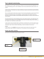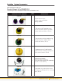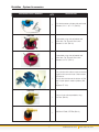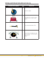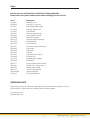
1
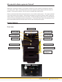
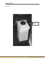
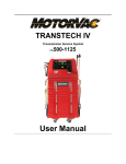
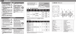
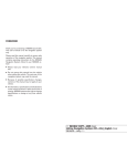
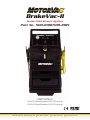
BrakeVac-II
Brake Fluid Service System
Part No. 500-8100/500-8105
USER MANUAL
500-8100 (Serial Numbers 8100-1200 and up)
500-8105 (Serial Numbers 8105-0700 and up)
1324 Blundell Rd. Mississauga ON
Tel. 905.615.8620
Fax. 905.615.9745
www.motorvac.com
Introduction
Congratulations you now own the cleanest, most efficient and user-friendly brake fluid service machine available
today. Your new electric pressure brake bleeder is designed specifically for modern hydraulic brake and clutch
systems. It is advised that only professional technicians perform brake system service.
The MotorVac BRAKEVAC-II equipment has been designed for use on all hydraulic brake and clutch systems
especially Anti-Lock Braking Systems. The simplicity of our pressure bleeder makes it very user friendly and eliminates the need for hands-on training.
The large capacity reservoir allows for a single service on any vehicle. The fluid should be drained and kept in a
sealed container between vehicle services as the onboard storage is not air-tight.
The MotorVac BRAKEVAC-II System allows years of clean, safe, one-man operation brake services.
Thank you for choosing MotorVac.
Sincerely,
The MotorVac Team.
[email protected]
www.motorvac.com
Table of Contents
Page
Why should the Brake system be Flushed? .………….....…………………………................................... 1
System Features ………………………………………………............…….………................................… 1-2
Safety Information & Precautions ………………………………………………............…….…….......…… 3
Brake Flush Service Procedure ………………………………………………............…….………..........… 3-4
Adjusting the pressure regulator ………………………………………………............…….…….........…… 4
Automatic low fluid level warning system and shut off …………………………............…….…….....…… 4
Emptying the tank after each use …………………..............…………………………….....…….………… 4
Tips for hydraulic brake bleeding ………………………………………………............…….…........……… 5
Suction hose filter assembly………………………………………………............…….……................…… 5
BrakeVac - System Accessories ………………………………………………............…….………........… 6-8
Parts ………………………………………………............…….………................….................................
[email protected]
9
www.motorvac.com
Why should the Brake system be Flushed?
Brake fluid is hygroscopic meaning it can absorb moisture from the air resulting in a dangerous reduction
of its boiling point. Water contaminated brake fluid under repeated working pressure boils and creates air
bubbles. Under severe conditions, this can result in complete brake system failure.
Water contaminated brake fluid causes electrolysis to occur inside the brake system. The oxygen contained
in the water droplets cause oxidation. Electrolysis and oxidation corrodes the hydraulic master cylinder and
wheel cylinders, and steel brake lines from the inside. Pressure bleeding has been proven the most effective
method in flushing and bleeding hydraulic brake systems. Flushing the brake system and replacing the dirty
and contaminated brake fluid with fresh brake fluid can often avoid expensive repairs.
System Features
Front view
Pressure switch
Vacuum switch
Pressure gauge
Pressure Regulator
Drain Tank Switch
Clean fluid tank
Circuit Breaker
Fluid level ‘window’
Clear vacuum hose
Black new fluid hose
12 volt DC power cord
Storage drawers
for adapters
1
[email protected]
www.motorvac.com
System Features
Back view
A
B
C
G
H
D
E
F
J
I
Waste (used)
fluid capture
tank
2
[email protected]
www.motorvac.com
Safety Information & Precautions
The following safety instructions should be observed at all times when opening the MotorVac BRAKEVAC-II.
•
Perform a visual inspection before each use. If the unit shows defects or damage, do not use! Have
your equipment repaired by an authorized MotorVac Service Center.
•
The MotorVac BRAKEVAC-II is to be used only in accordance with the operator’s manual.
•
The MotorVac BRAKEVAC-II is to be used only for the maintenance and repair of hydraulic brake fluid
and clutch systems.
•
Fill the MotorVac BRAKEVAC-II with BRAKE FLUID ONLY! Do not mix the different DOT standards
together. Never use the unit with any fluid other than BRAKE FLUID!
•
WARNING! USE OF FLUIDS OTHER THAN BRAKE FLUID CAN DAMAGE THE SEALS IN THE
PUMPS! USE OF OTHER FLUID CAN VOID THE WARRANTY!
•
Follow all instructions from the Brake Fluid Manufacturer. Read all cautions on the container. Use proper
precautions when coming into contact with brake fluid.
•
Keep your MotorVac BRAKEVAC-II clean. Wipe your bleeder with a clean rag and non-flammable
solvent. Wipe all residual fluids from the bleeder before use.
•
Do not put oil, gasoline, or solvent soaked rags on the bleeder, as this will create a fire hazard.
•
Use only manufacturer’s recommended adapters and accessories. Always follow the vehicle
manufacturer’s service and maintenance instructions.
Brake Flush Service Procedure
1. Remove the fill cap from the MotorVac BRAKEVAC-II clean fluid tank and fill with new brake fluid. You
can observe the fluid level by looking at the level indicator window at the front of the unit. Replace the fill
cap.
2. Attach the power cord to a good 12 volt DC power source.
3. Install the proper master cylinder reservoir adapter and connect the black pressure hose coupling to the
adapter.
4. Turn the pressure switch to the ON position and check for leaks.
5. Adjust the pressure regulator until the desired pressure is reached. (45 lb. maximum). Do not over
pressurize the reservoir as it may become damaged. To set pressure, relieve any residual pressure from
the service hose by inserting the ‘fill’ adapter into the coupler at the hose end. Open the regulator valve
‘counter-clockwise’ before starting the pump. If control knob is locked, pull outward slightly until knob
clicks off the locking tab. After starting the pump adjust the regulator in ‘clockwise’ until the correct
pressure reading is obtained. Control knob can be locked by pushing knob ‘in’ towards control panel.
6. Attach the transparent (vacuum) hose to the bleeder adapter and connect to the vehicle’s first wheel
bleeder valve in the sequence. Turn on the “Vacuum” switch. Open the bleeder valve and observe the
fluid flow. When the fluid is clean, close the bleeder valve.
7. Bleed the brake system according to manufacturer’s recommended sequence by moving the vacuum
3
[email protected]
www.motorvac.com
Brake Flush Service Procedure (Cont’d)
hose from bleeder to bleeder in the proper sequence.
8. When finished, turn the “Pressure” switch and the “Vacuum” switch to the OFF position. The pressure
will automatically relieve from the new fluid hose. When the pressure on the gauge reaches 0 psi
disconnect the new fluid hose from the master cylinder adapter. Adjust the fluid level using adapters in
either vacuum or pressure hoses as required.
9. Remove master cylinder adapter.
10. Reinstall the original master cylinder cover.
11. Empty the waste capture tank into a recycle container.
12. Empty the new fluid back to a sealed new brake fluid container to keep it dry and ready for the next
vehicle service
Note: If the Pressure Bleeder does not operate when the switch is in the ON position, check the circuit
breaker mounted in the front of the unit. Replace if necessary or contact your MotorVac BRAKEVAC-II
service center.
Adjusting the pressure regulator
The pump has a preset pressure of 45 PSI/ or 3 bar by the manufacturer. In some cases the recommended
procedure may call for a lower pressure. Release the locking knob by pulling outward then turn the knob
counter-clockwise to open the regulator to the lowest pressure setting. Then turn on the ‘Pressure’ pump
and turn the regulator knob in clockwise (when starting from 0 PSI on the pressure gauge) until the proper
pressure is reached.
Automatic low fluid level warning system and shut off
The MotorVac BRAKEVAC-II will shut off the clean fluid pump automatically when the fluid level in the tank
reaches 0.8 liters. This ensures that no air will be injected into the brake system. The low level warning
light will illuminate alerting you to the low level condition. Remove the fill cap and add fluid and replace cap.
Continue bleeding where you left off.
Emptying the tank after each use
Use the Pressure hose and attach an adapter that will allow brake fluid to be drained into a container. Place
the adapter in a fashion that will allow the brake fluid to drain into a clean capture tank or bottle.
Turn on the “Pressure” switch to drain the brake fluid. Brake fluid will start to flow immediately when the
“Pressure” switch is turned to the ON position. The tank level switch will turn off the flow when the brake fluid
tank is almost empty. To drain the remainder of the brake fluid from the tank and hose, press and hold the
“Drain Tank” switch until the brake fluid tank and hose is completely empty. Release the “Drain Tank” switch
and turn off the “Pressure” switch.
After filling the tank with new fluid, attach any adapter to the black hose coupler and direct the fluid flow to a
capture container. Turn on the “Pressure” switch to bleed all the air out of the black hose prior to beginning a
new service.
The unit is now ready for the next service.
4
[email protected]
www.motorvac.com
Tips for hydraulic brake bleeding
After installing the correct master cylinder reservoir adapter and connecting the MotorVac BRAKEVAC-II you
can begin the bleeding process. Open one bleeder at a time until the brake fluid flows clean and free of air
bubbles.
To better observe the brake fluid flow and insure cleanliness of the shop we recommend using the MotorVac
‘vacuum’ recovery. This will allow you to observe the fluid color, keep the fluid off the shop floor and allow for
easy fluid disposal.
After a complete hydraulic brake system overhaul we recommend that all bleeders be opened simultaneously
so the air can escape by the path of least resistance. This process eliminates backpressure and the
possibility of the new fluid mixing with contaminated brake fluid remaining in the system. When the fluid
flows clean and free from bubbles, close the bleeder nipples and tighten them one after the other and double
check tightness.
We recommend during this pressure bleeding process to slowly press the brake or clutch pedal a few times
to insure complete purging of air and fluid between the primary and secondary master cylinder chamber.
Fixed calipers can be equipped with multiple bleeder valves, which can require a larger volume of brake fluid.
Each bleeder valve must be bled one after another.
In brake systems with load sensitive brake force regulators, the hydraulic flow to the wheel cylinders may be
restricted when the axles are hanging during lifting. In this case, the axles must be put under load. Consult
manufacture’s repair manual for proper brake bleeding or brake fluid replacement procedures.
Caution:
In brake systems with a hydraulic brake booster, the brake system operates with brake fluid and the
hydraulic booster system operates on hydraulic fluid. The two fluids must not be interchanged!
Suction hose filter assembly
Filter screen must be cleaned routinely to avoid loss of suction.
Elbow part number
030-4814
Filter part number
050-1009
Unscrew cap to
clean filter screen
5
[email protected]
www.motorvac.com
BrakeVac - System Accessories
Basic Adaptor Kit: 200-3118
Standard Adapter kit for BRAKEVAC-II
The following is a list of the adaptors included with your BrakeVac-II unit.
QTY
MOTORVAC PART & NUMBER
DESCRIPTION
066-6000
1
Chrysler with twin caps,
2 piece, 3 tabs, expandable
O-rings. (BA-01)
1
3 Tab twist on with Expandable o-ring.
Fits Ford, Hyundai, Chrysler, Kia, Mazda,
Pontiac, Nissan and Subaru. (BA-03)
066-6002
066-6003
1
Three tab twist on with expandable o-ring.
Fits GM, Chevrolet, Cadillac, Mazda,
Pontiac and Daewoo. (BA-04)
066-6004
1
Threaded screw cap. Fits all European
makes as well as domestics with Bosch or
Teves master Cylinders. (BA-05)
066-6005
1
Universal round adapter
With chain tension hold down.
Fits round master cylinders with a diameter
of .800” to 3.150”. (BA-07)
066-6006
1
6
Expandable O-ring with hold down chain.
Fits Honda with diameter of 2.91” and some
Isuzu. (BA-08)
[email protected]
www.motorvac.com
BrakeVac - System Accessories
MOTORVAC PART & NUMBER
QTY
DESCRIPTION
1
Fits Honda master cylinders with and Inside
diameter of 2.11” to 2.17”. (BA-09)
066-6007
066-6008
1
Expandable o-ring with adjustable hold
down tabs. Fits Toyota & Lexus with
diameter of 1.69” (BA-10)
066-6009
1
Expandable o-ring with adjustable hold
down tabs. Fits Toyota & Lexus with
diameter of 2.75”. (BA-11)
066-6010
1
Twin cylinders with rubber cones connected
together with common hose. Chain tension
hold downs.
Fits into the inlet holes at the bottom of GM
and Chrysler plastic master cylinders. (BA14)
(replaces ST-100)
066-6012
1
Twist on 2 tab with expandable o-ring.
Fits Ford. (BA-02)
066-6013
1
7
NISSAN ALTIMA, XTERRA (BA-13)
[email protected]
www.motorvac.com
OPTIONAL ADAPTORS (NOT INCLUDED IN KIT 200-3118.)
QTY
MOTORVAC PART & NUMBER
DESCRIPTION
066-1100
1
Honda Civic adapter
066-6011
1
Plate adapter with 2 hold down chains for
rectangular cast iron master cylinders.
(BA-12)
066-6014
1
Clutch master/slave adapter. (ST-67)
066-0020
1
8
Small universal round adapter with chain
tension hold-down. Specially designed for
clutch reservoirs.
(BA-06)
[email protected]
www.motorvac.com
Parts
Service parts for the BrakeVac-II, Brake Fluid Flushing Machine.
Please refer to the part numbers below when ordering parts for this unit.
Part #
010-0027
040-0604
040-0507
010-6008
011-0051
020-8207
020-0038
020-0090
200-8119
050-1308
020-1205
020-1201
020-0063
020-0073
020-0083
020-1402
010-6060
010-7050
050-1009
200-8111
080-8101
080-8102
200-8112
ZIM13-00828 200-8125
Description
Wheel (8 x 1.75)
Cap Nut (1/2” push on)
Axle Bushing (Black Nylon)
Axle, rear wheels (1/2”)
Hose Bracket
Harness, external power
Circuit breaker (15 amp)
Relay (ear mounted)
Pressure regulator assembly
Pressure gauge
On/off switches
Drain tank switch (momentary)
Light-amber
Light-green
Light-red
Low level switch (in tank)
Fluid tank cap
Waste fluid tank (I gallon)
Screen filter
Output pressure hose assembly
Coupler only - Output side ¼”
Adapter brake bleeder
Suction hose assembly
Operators Manual
Pump Kit BrakeVac II
ORDERING PARTS
Parts for the unit may be ordered by calling MotorVac Customer Service at (800) 841-8810 or
(905) 615-8620. Please have your model and serial numbers available.
www.motorvac.com
[email protected]
9
[email protected]
www.motorvac.com
10
[email protected]
www.motorvac.com
ZIM13-00828 Rev2
1324 Blundell Rd. Mississauga ON
Tel. 905.615.8620
Fax. 905.615.9745
www.motorvac.com