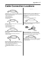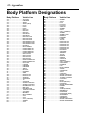
1
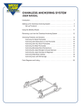
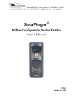
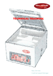
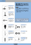
D IAGNOSTIC
AND
REPROGRAMMING
TOOL
USER’S MANUAL
VERSION 3.0
IMPORTANT NOTICE
SAFETY
All Danger, Warning and important notes must be followed for your safety. These safety messages will be
in the following formats:
• Danger means you may risk possible loss of life;
• Warning means you may risk bodily harm;
• Important means you risk damage to the vehicle or the tool;
• Notes are added to provide clarity and helpful tips.
These safety messages cover situations SPX is aware of. SPX cannot know, evaluate and advise you as
to all of the possible hazards. You must be certain that your personal safety is not jeopardized by any
conditions or service procedures encountered.
COPYRIGHT
No part of this manual may be reproduced, stored in a retrieval system or transmitted, in any form or by
any means, electronic, mechanical, photocopying, recording, or otherwise, without the prior written
permission of SPX.
DISCLAIMER
All information, illustrations, and specifications contained in this technical instruction manual are based on
the latest information available at the time of publication. The right is reserved to make changes at any
time without obligation to notify any person or organization of such revisions or changes. Further, SPX
shall not be liable for errors contained herein or for incidental or consequential damages (including lost
profits) in connection with the furnishing, performance or use of this material.
Getting Started • 1
Contents
Precautions
Welcome .................................................. 2
D.A.R.T. Basics ....................................................... 2
Read Me First: Registration and Software Update .. 4
How to Update a Controller .................... 8
Required Documentation ........................................ 8
About Cable Setup .................................................. 8
How do I Update a Controller .................................. 8
About Diagnostic Trouble Codes .........11
How to Connect the Cable ..................................... 11
How to Read Diagnostic Trouble Codes ................ 11
How to Program the Sentry Key .......... 12
How to Connect the Cable .................................... 12
How to Program Keys ........................................... 12
How to Erase Keys ................................................ 12
About Customer Preferences .............. 13
How to Connect the Cable .................................... 13
How to Set Customer Preferences ........................ 13
Miscellaneous Tests ............................. 14
About Pinion Factor ............................................... 14
About Clutch Volume Index ................................... 14
About Vehicle Identification ................. 15
How to Identify a Vehicle .......................................
How to Read an Engine Identification Number .....
How to Read a Transmission Identification Number
How to Save an Identification Number to Memory
15
15
15
15
About Modem Setup ............................. 16
About Dial-Up Number .......................................... 16
About Modem Initiation String ............................... 16
About Call Waiting Service .................................... 17
Appendix
D.A.R.T. Menu View ...............................
Cable Connection Locations ................
Body Platform Designations ................
Index .......................................................
18
21
22
23
Danger
• When an engine is operating, keep the
service area WELL VENTILATED or
attach a building exhaust removal
system to the engine exhaust system.
Engines produce carbon monoxide, an
odorless, poisonous gas that causes
slower reaction time and can lead to
serious injury or death.
Warning
• Set the parking brake and block the
wheels before testing or repairing the
vehicle. It is especially important to
block the wheels on front-wheel drive
vehicles because the parking brake
does not hold the drive wheels.
• Be sure there is adequate clearance
between any moving components when
testing. Moving components and belts
can “catch” loose clothing, parts of your
body or the test equipment and cause
serious damage or personal injury.
• Wear an ANSI approved eye shield when
testing or repairing vehicles. Objects can
be propelled by whirling engine components and liquids escaping under
pressure can cause serious injury.
• Automotive batteries contain sulfuric
acid and produce explosive gases that
can result in serious injury. To prevent
ignition of gases, keep lighted cigarettes, sparks, flames, and other ignition
sources away from the battery at all
times. If you are using the battery as a
power source, connect the RED (+)
battery clip to the positive vehicle
battery terminal and connect the BLACK
(-) battery clip to a good ground away
from the battery.
Important:
• Do not leave the tool for prolonged periods in the
direct sunlight, the display may darken due to excess
heat.
Reprog Scan Tool:
❚➤REPROGRAM VEHICLE
2- GENERIC OBD II
↓
3- TROUBLE CODES
2 • Getting Started
Welcome
The Diagnostic and Reprogramming Tool (D.A.R.T.) is
designed to reprogram vehicle controller software programs
or change function settings on a Chrysler vehicle easier and
faster. This tool is designed to access the following areas:
• Reprogramming–when Chrysler releases software
updates for vehicle controllers, or when additional
functions and capabilities are added to the D.A.R.T.
programming, you have the ability to update a vehicle or
tool program with the software you download from the
OTC Bulletin Board System
• Reset Customer Preferences–comfort and convenience features on Chrysler vehicles can be changed to
meet the customer’s desires. Turn warning chimes on or
off, enable or disable automatic door locks, set the
headlights to come on with the windshield wipers, and
more.
• Locksmith Function–many new Chrysler vehicles are
equipped with a Sentry Key Immobilizer System (SKIS).
This system uses a vehicle immobilizer to prevent
vehicle theft. D.A.R.T. can program the SKIS driver’s key
to the vehicle or erase the key from the vehicle system if
it is lost or stolen.
• Diagnostic Trouble Code Reader–Read and erase
Diagnostic Trouble Codes (DTCs) on generic OBD II
systems plus 1989-’98 Chrysler Engine Management
Systems, SIR, BODY and many other Chrysler systems.
D.A.R.T. Basics
The D.A.R.T. is an easy-to-use test instrument that will
stand up to rugged use. Take a moment to familiarize
yourself with the basic functional areas.
1
2
3
1. DB25 Port – Adapter cables plug into the DB25 port.
2. Display Window – display data and messages to the user.
3. Keypad – enter data and reply to tester messages. Keys listed
perform the following functions:
• UP/DOWN arrow keys–press to move through menus or
move the Selector Cursor up or down.
• LEFT/RIGHT arrow keys–press to move the Selector Cursor
left, right, or move screen by screen through the menus.
• F1/F2 keys–future option.
• ENTER keys–enter your command into the tester.
• EXIT keys–go back to the previous menu or test.
• HELP key–display additional information.
• RECORD key–future option
Figure 1.1: D.A.R.T.
CONTINUED ON NEXT PAGE...
Getting Started • 3
Cable Connection Error Messages
Typical Cable Setup
The D.A.R.T. produces an error message when it does not
get a signal response (Fig. 1.2).
1. Refer to Cable Connections Locations in the Appendix to determine which cables are required to
connect the tool to the vehicle and to determine
where the connector is located on the vehicle.
No Response, Check
Cable, Ignition or
D.A.R.T. Support Matrix.
Press EXIT to Exit
2. Connect the cables to the D.A.R.T. and to the vehicle
Data Link Connector or to the controller.
Figure 1.2: Error Message
J1962/MMC, J1962 or
MMC Cable
An error may occur for the following reasons:
• Poor connection: Check all cables and connections for a
tight fit and try again.
• Low battery voltage: Recharge the battery.
• Wrong cable used to connect to the Data Link Connector:
Verify that the correct cable is used.
• Under certain circumstances the vehicle may lose
communications with the D.A.R.T. tool. Switch the
vehicle ignition off, wait 15 seconds and then switch the
ignition on.
DIN Cable
CCD Cable or SCI
Engine Cable
Typical setup to vehicle Data Link Connector
Program Icons
Program icons signal when functions are available or must
be used to access more information.
Connect Red to Battery + and
Black to Battery – Terminal
DIN Cable
↔
• The Arrow Icon means more information is available.
Press the ↓ or ↑ key to view the next screen.
Figure 1.6: Data Link Connector Cable Setup
Figure 1.3: Arrow Keys
• Press the HELP key to view additional instructions or
information.
EATX II
Programming
Kit
EATX II Controller
Connect to
EATX II
Controller
H
Typical setup for vehicle EATX II (Transaxle) Controller
Figure 1.4: Help
• Move the Selector Cursor with the ↓ or ↑ arrow key to
position it beside an option you want to select, and
then press ENTER.
❚➤
Figure 1.5: Selector
Figure 1.7: EATX II Controller Setup
3. Supply power to the tool, the program will automatically initialize and identify the vehicle.
Power is supplied to the D.A.R.T. when the cable is
connected to the Data Link Connector (DLC), the controller,
or when the cable battery clamp (if so equipped) is connected to the battery.
4 • Getting Started
Read Me First: Registration
and Software Update
Before you can use all of the features of your D.A.R.T., you
must first perform two steps to set up your D.A.R.T. Tool:
• Register your subscription on the OTC Bulletin Board
System (BBS).
• Download the D.A.R.T. program software to update your
D.A.R.T. into a fully operational tool.
How to Update D.A.R.T. Software
Set up the D.A.R.T. with a modem to communicate with the
OTC Bulletin Board Service (BBS).
1. Attach the Modem/Power Cable to the D.A.R.T. DB25
Port (see Fig. 1.9).
1
2
How to Register
For immediate registration, telephone 800-926-9430 and
provide the information required from the D.A.R.T. Registration form, or fax your D.A.R.T. Registration form to 800-2838665 for activation within 24 hours.
3
1. DB25 Port
2. Modem/Power Cable
3. 12 Volt AC/DC Wall Transformer (D.A.R.T.)
Figure 1.9: D.A.R.T. Setup
2. Supply DC power (Item 3) to the D.A.R.T., as illustrated (see Fig 1.9).
The DART will initialize the program and display a Main
Menu when power is supplied. Press the ↑ or ↓ key to
position the Selector Cursor beside SYSTEM CONFIG, and
press ENTER to select it.
Figure 1.8: Registration Form
D.A.R.T. Main Menu
❚➤SYSTEM CONFIG
8- MISC. FUNCTIONS
1- REPROG VEHICLE
Figure 1.10: Main Menu
IMPORTANT: The Locksmith option for the D.A.R.T. tool
relates only to the SKIM FUNCTION and the SYSTEM
CONFIG(uration) function even though the entire menu
structure for the DART tool is displayed.
3. Turn telephone service Call Waiting features off, or
go to step 4 if you DO NOT have Call Waiting.
How to Turn Call Waiting off:
Call Waiting telephone services must be turned off to
prevent disruption of data during a download from the BBS.
Your Call Waiting Code may be different than the standard
call waiting code set as a default. Your applicable call
waiting defeat code is generally listed in your area telephone book, or call your local telephone service to find out
what it is.
CONTINUED ON NEXT PAGE...
Getting Started • 5
The steps to turn Call Waiting off are:
• Select DIAL PREFIX CODE from the SYSTEM CONFIG
menu (See Fig 1.11).
The steps to change the BBS dial-up sequence are:
• Select BBS NUMBER from the SYSTEM CONFIG menu
(See Fig 1.13).
System Configuration
1-BBS NUMBER
2-DIAL PREFIX: ON/OFF
❚➤DIAL PREFIX CODE
System Configuration
❚➤BBS NUMBER
2-DIAL PREFIX: ON/OFF
3-DIAL PREFIX CODE
4-MODEM INIT STRING
5-DISPLAY TOOL INFO
6-DEFAULT CONFIG
4-MODEM INIT STRING
5-DISPLAY TOOL INFO
6-DEFAULT CONFIG
Figure 1.11: System Configuration
• Enter your Call Waiting Defeat Code if it is different than
the pre-set *70: Press the ←or → key to move the
cursor left or right, press the ↑ or ↓ key or key in the
number to change the setting. Press ENTER to save
changes (See Fig. 1.12).
↔
Edit Call Waiting
H
to Move, to Edit
❚✳70,
Press ENTER to Save
↔
Figure 1.12: Edit Call Waiting
• Select DIAL PREFIX:(ON or OFF) from the SYSTEM
CONFIG menu, and then press ENTER to toggle the
DIAL PREFIX:(ON or OFF) to display DIAL PREFIX:ON
Figure 1.13: System Configuration
• Press the ←or → key to position the cursor.
• Key in the number or press ↓ or ↑ to scroll the correct
number in place.
• Place one comma for each one second delay, if
required. Spaces and hyphens are ignored during
dialing.
• Press ENTER to save changes.
Edit BBS Number
← or → to move, ↑ to edit
91,,❚07-455-4999
Press ENTER to save
Cursor
Figure 1.14: Edit Screen
Call Waiting will be restored, for most telephone services,
when you disconnect from the BBS. Some older telephone
systems may not automatically reconnect and will require a
specific Call Waiting reconnect routine as provided by the
telephone service provider.
Note: The Dial Prefix-Off setup will automatically turn the
Call Waiting off each time you connect to the BBS unless
you change the setting.
4. Add an “outside line” number to the BBS dial-up
number sequence, or go to step 5 if you DO NOT
have an internal telephone system that requires a
number before you can call outside your internal
telephone system.
How to Change the BBS Dial-Up Number:
A dial-up number can be changed or numbers, pauses and
symbols may be added to select an outside telephone line
from within an internal telephone system.
5. Add any modem initiation changes required for
access through your telephone; for example, you
may have a pulse telephone instead of the standard
tone telephone, or additional codes are required to
go through your telephone service provider. SKIP
STEP 5 and go to step 6 if you have a standard tone
telephone system and no special conditions are
required by your telephone service provider.
How to Change the Initiation String:
Communication with your telephone service provider
sometimes requires that additional codes be set in the dialup string: For example, change the setting to support a
pulse telephone by adding P to the modem initialization
string (AT&F0 to AT&F0P). please refer to the manual
included with the modem for a complete listing of code
variations available to complete the initiation string.
The steps to change the initiation string sequence are:
• Select MODEM INIT STRING from the System Configuration menu.
• Press the ←or → key to position the cursor.
• Key in the number or press ↓ or ↑ to scroll the correct
number or letter in place.
• Press ENTER to save changes.
6 • Getting Started
8. Connect the modem to an analog telephone line.
System Configuration
1-BBS NUMBER
2-DIAL PREFIX: ON/OFF
3-DIAL PREFIX CODE
9. Turn on the modem switch, the modem will automatically initialize itself.
❚➤MODEM INIT STRING
5-DISPLAY TOOL INFO
6-DEFAULT CONFIG
10. Turn the DART on by connecting it to the 12 volt
wall transformer.
Figure 1.15: System Configuration Screen
The DART will initialize a startup porcedure and recognize
the modem setup. A dial-in routine will begin, progress
screens will keep you informed and a screen will show when
you are connected to the server. Press ENTER to continue
the update process or EXIT to quit.
Edit Modem Init
← or → to move, ↑ to edit
AT&❚F0&Q5&KOEVO
Press ENTER to save
Cursor
Figure 1.16: Modem Initiation Configuration Screen
6. Turn the DART off by disconnecting it from the 12
volt wall transformer.
7. Connect the D.A.R.T. to the modem as illustrated in
Fig. 1.17. Supply power to the modem with the 9 volt
wall transformer.
1
2
VERSIONS
Server 1.5
TIL T1157-000
Press ENTER to cont.
Figure 1.18: Server Screen
A TOOL UPDATE available screen will appear next.
TOOL UPDATE AVAIL
OT6000v 2.2 498 K
Controller program
files will be lost
3
update may take 20 minutes.
Press ENTER to Load
Press EXIT to cancel
Figure 1.19: Tool Update Screen
6
4
5
Socket for Modem/Power
cable connector
Socket for telephone
(do not use)
Note: Updates may take up to 20 minutes. The condition of
your telephone line affects the download transfer rate.
BBS Connection Error Messages:
I
O
9V-AC
Switch
You will also see a message stating that controller files will
be lost. This is not applicable to this update. Press ENTER
to load the update or EXIT to quit.
DTE
Socket for 9
volt transformer
LINE
PHONE
Socket for
modem to
telephone jack
The D.A.R.T. produces an error message when it does not
get a signal response.
No Response, Check
Cable, Ignition or
D.A.R.T. Support Matrix.
Press EXIT to Exit
Figure 1.20: Error Message
1. DB25 Port
2. Modem/Power Cable
3. Modem to Telephone Jack Wire
4. 9 Volt AC/DC Wall Transformer (modem)
5. 12 Volt AC/DC Wall Transformer (D.A.R.T.)
6. Modem
Figure 1.17: D.A.R.T. and Modem Setup
Press EXIT to reconnect to the BBS. If the error continues,
unplug the wall transformer for the D.A.R.T., the modem,
and also detach the cables. Check to be sure you are
plugged into an analog telephone line. Re-attach the cables,
wall transformers and try again. If the error persists, call
technical service at 800-533-6127.
Getting Started • 7
How to Update a D.A.R.T. Manual
As future updates to the D.A.R.T. operating system are
made available for download to your tool, the D.A.R.T.
User’s Manual will also be be made available for download
to your computer. Simply access the OTC World Wide Web
site located at http://www.otctools.com and click on the
Product Manuals icon to download an updated User’s
Manual. You may also order an updated User’s Manual
through your SPX/OTC tool supplier.
8 • Reprogramming Procedures
How to Update a Controller
About Cable Setup
Chrysler software updates for engine or transmission
controllers can be performed with the D.A.R.T. But first,
there are documentation and labeling issues that you must
be aware of before you update a vehicle controller.
Required Documentation
Updates to software for engine or transmission controllers are published in Chrysler Technical Service
Bulletins (TSBs). A Chrysler Technical Service Bulletin
must specify that a control module update is required
before you may reprogram any engine or transmission
controller. In addition, there may be laws that specify
what documentation is required before you can reprogram a vehicle controller.
Once the controller software is updated, you must place an
Authorized Software Update Label on the vehicle controller
and an Authorized Modification Label beside the Vehicle
Emission Component Information (VECI) label.
Additional vehicle component replacement–if required with
the controller update–is also specified on the same TSB. It
is important that the entire TSB be read and all requirements carried out to ensure that all components of the
update are completed.
To Get Technical Service Bulletins
Technical Service Bulletins (TSB) are prepared by the
Chrysler Corporation and then distributed to Chrysler
Dealerships. Your local Chrysler Dealership is your best
source for TSBs that specifically address any drivability
problems and corrective actions. Additional sources are:
• Chrysler Training Publications
• Service information resources such as OTC Drivability
TSB Manuals
• Federal Government World Wide Web site located at
http://www.Fedworld.gov/cleanair/search.htm
The D.A.R.T. cable setup configuration requires one setup
to connect the tool to the OTC Bulletin Board System (BBS)
to download programming information and a second setup
to connect the tool to the vehicle controller or Data Link
Connector (DLC). To determine which cable is required for
your application, Refer to Cable Connector Locations in the
Appendix.
How do I Update a
Controller
Step 1: Connect the D.A.R.T. to the
vehicle controller to determine the
controller part number.
1. From the Main Menu screen, press the ↓ key until the
❚➤ icon points to VEHICLE ID, and then press ENTER
to select.
Main Menu:
3- SKIM FUNCTIONS
4- CUST PREFERENCE
❚➤VEHICLE ID
↓
Figure 2.2: Select Vehicle
2. From the Vehicle ID menu, select READ ENGINE ID #
or READ TRANS ID #, and then press ENTER to
select.
Vehicle ID:
❚➤READ ENGINE ID #
2- READ TRANS ID #
3- STORE ID #
Figure 2.3: Select Store ID Number
The DART will read and display the Controller Identification
number. Exit the ID screen and go to the next step.
3. From the Vehicle ID menu, select STORE ID #, and
then press ENTER to select.
Vehicle ID:
1- READ ENGINE ID #
2- READ TRANS ID #
❚➤STORE ID #
Figure 2.4: Select Store ID Number
Figure 2.1: Technical Service Bulletin
The tool will save the data into memory. Press EXIT twice to
return to the Main Menu screen.
4. Detach the cable from the tool.
CONTINUED ON NEXT PAGE...
Reprogramming Procedures • 9
Step 2: Connect the D.A.R.T. to the BBS.
5. Attach the Modem/Power Cable to the DART DB25
Port and to the Modem (see Fig. 2.5).
1
2
3
Important: a D.A.R.T. update erases all controller
update files stored in the D.A.R.T. Directory List.
Note: There are no controller update files stored in the tool if
this is the first time you are getting controller update files
from the BBS.
Tool update available.
OTxxxx v.xx.x xxxxk
Controller program files
will be lost. Update will
6
take up to 20 minutes.
Press ENTER to load
Press EXIT to cancel
4
5
1. DB25 Port
2. Modem/Power Cable
3. Modem to Telephone Jack Wire
4. 9 Volt AC/DC Wall Transformer (modem)
5. 12 Volt AC/DC Wall Transformer (D.A.R.T.)
6. Modem
Figure 2.5: D.A.R.T. and Modem Setup
6. Supply DC power (Item 5) to the D.A.R.T., as illustrated.
The DART will initiate a Main Menu display when power is
supplied.
Note: Call Waiting service—if you have this feature for your
telephone line— should have been turned off when you
registered and updated your D.A.R.T. software. The DART
setup for the Bulletin Board System (BBS) will automatically
turn the call waiting off again until you finish communicating
with the BBS.
7. Connect the D.A.R.T. to the modem as illustrated in
Fig. 2.5. Supply power to the modem with the 9 volt
wall transformer: The modem will automatically
initialize itself, and then dial into the BBS.
Note: If there is an ERROR response, press EXIT and retry.
If the error continues, unplug the wall transformers, the
modem, and also detach the cables; reattach the cables,
wall transformers and try again. If the error persists, call
technical service at 800-533-6127.
The BBS will check the revision level of the D.A.R.T.
software. It will notify you if there is an update and let you
make the choice if you want to automatically update the
D.A.R.T. software. Press EXIT if you want to update at a
later date.
Figure 2.6: Warning Screen
Tool update time may vary significantly due to variations in
the telephone line quality.
8. The BBS will offer two options for submission of
controller update information, select one:
• DIRECT PART NUMBER—Submit the controller part
number stored in memory to the BBS, or enter a
number manually (press ← or → to position the
cursor, press ↓ to ↑ change the number).
• VEHICLE DESCRIPTION—Enter a vehicle description to be submitted to the BBS.
Part Selection
❚➤DIRECT PART NUMBER
VEHICLE DESCRIPTION
Figure 2.7: Submit Options
If DIRECT PART NUMBER is selected: A screen to verify
the number or request additional vehicle option information
will be displayed before the download program is initiated.
If VEHICLE DESCRIPTION is selected: A series of screen
queries will be displayed. An accurate response to each
query is required.
Enter Part Number
XXXXXXXX
Press ENTER to load
Figure 2.8: Direct
Part Number
Select: Model Year
❚➤1994
1995
Select:
Body Style
1996
❚➤FJ11
JA
Select:
LH Engine
❚➤3.3L V6(SFI) N-S GAS
3.3L V6(SFI) N-S FLEX
Select:
3.5LOptions
V6(SFI) 24V GAS
❚➤50 STATE AUTO HI SPEED
50 STATE AUTO NORMAL
93-95LH ALL ENGINES
Figure 2.9: Vehicle
Description
When the BBS has completed the download, disconnect the
D.A.R.T. from the modem.
10 • Reprogramming Procedures
Step 3: Reconnect the D.A.R.T. to the
vehicle controller.
Step 4: Complete any steps remaining in
the TSB.
9. The D.A.R.T. will initialize and display the Main Menu
screen. Press the ↓ key until the ❚➤ icon points to
REPROGRAM VEHICLE, and then press ENTER to
select.
Step 5: Attach the labels–as required by
law–to the vehicle and to the
reprogrammed controller.
Main Menu:
❚➤REPROGRAM VEHICLE
2- TROUBLE CODES
↓
3- SKIM FUNCTIONS
Figure 2.10: Reprogram Vehicle
10. Select REPROGRAM ENGINE or REPROGRAM
TRANS from the Reprogram Vehicle menu.
Reprogram Vehicle:
❚➤REPROGRAM ENGINE
2- REPROGRAM TRANS ↓
3- DIRECTORY LIST
Authorized Software Update Label Requirements:
Each time a software update is made to a vehicle, you must
enter the information required onto the Authorized Software
Update label and attach this label onto the vehicle as
directed. Important: The Authorized Software Update
label is required by law.
a. Fill out the Authorized Software Update label with the
following information:
• The part number of the updated controller;
• Your Dealer Code or D.A.R.T. serial number;
• The date
.
Figure 2.11: Select Reprogram
Additional transmission choices (such as EATX2, EATX3 or
EATX3 MMC) may be offered. Select the appropriate
configuration, and then respond to any directions displayed
as the D.A.R.T. guides you through the reprogramming
process.
Important: The vehicle computer/controller may be
damaged beyond repair if a power cable or adapter
cable is removed during the reprogramming step.
As the D.A.R.T. downloads the selected programming file to
the vehicle computer/controller, follow the instructions
displayed on-screen.
If the computer/controller programming is current or if the
program is invalid for the vehicle, the tool will immediately
stop the procedure before any change takes place.
About the Directory List:
Previously downloaded programs are stored in D.A.R.T.
memory and may be used if appropriate. If, during a
download, the directory list is filled, you will have to delete a
file to make room for the new file, follow the on-screen
prompts.
Figure 2.13: Authorized Software Update Label
b. Attach the label on top of the controller and place the
accompanying clear sticker over the top of the label.
Authorized Modification Label Requirements:
Each time a software update is made to a vehicle, you must
enter the update data required onto the Authorized Modification label and attach this label onto the vehicle as
directed. Important: The Authorized Modification label is
required by law.
a. Fill out the Authorized Modification Label with the
following information:
• The part number of the updated controller;
• The change authority (TSB number);
• Your Dealer Code or D.A.R.T. serial number;
• The date.
To re-use a file, select DIRECTORY LIST from the Reprogram Vehicle menu, and choose the proper program.
Directory List:
❚➤XXXXXXXXX
2- XXXXXXXXX
3- XXXXXXXXX
Figure 2.12: Select File
Figure 2.14: Authorized Modification Label
↓
b. Attach the label on the vehicle near the Emission
Component Information (VECI) label.
Reprogramming Procedures • 11
About Diagnostic Trouble Codes
Diagnostic testing is one of the functions performed by the
vehicle management system. The Powertrain Control
Module (PCM) monitors the system and performs activity
tests when passive tests fail. A Diagnostic Trouble Code
(DTC) is recorded in the vehicle computer memory if the
PCM determines that a component may have failed.
The D.A.R.T. reads and displays the DTCs recorded in the
PCM.
How to Connect the Cable
1. Refer to Cable Connector Locations in the Appendix
to determine which cables are required to connect
the D.A.R.T. to the vehicle and to determine where
the connector is located on the vehicle.
2. Connect the cable to the tool and to the vehicle
connector.
3. Supply power to the tool, the program will automatically initialize and identify the vehicle.
Power is supplied to the D.A.R.T. when the cable is
connected to the DLC or when the cable battery clamp (if so
equipped) is connected to the battery.
How to Read Diagnostic
Trouble Codes
1. From the D.A.R.T. Main Menu, select TROUBLE
CODES or GENERIC OBD II.
Select TROUBLE CODES to see DTCs for all vehicle
systems. Select GENERIC OBD II to see DTCs for the
Emissions System.
Main Menu:
1- REPROGRAM VEHICLE
2- GENERIC OBD II
↓
❚➤TROUBLE CODES
Figure 2.15: Main Menu
2. Select a vehicle system to view if you selected
TROUBLE CODES.
Select System:
1- ENGINE
2- TRANSMISSION
❚➤BODY
↓
Figure 2.16: Vehicle Systems
3. From the DTC menu, Select your task choice.
DTC Review Press:
❚➤REVIEW CODES
2- CLEAR CODES
FIGURE 2.17: Generic OBDII DTC Menu
REVIEW CODES: Display the DTCs recorded in the
vehicle controller. Press the ↑ or ↓ key to position the
code to the top of the list, press ENTER to see the code
description.
CLEAR CODES: Select to clear (erase) all DTCs from
the vehicle controller memory. This will clear all OBD II
data, including readiness status.
DTC Menu
❚➤ACTIVE DTCs
2- ONE TRIP DTCs
3- ERASE DTCs
Figure 2.18: Trouble Code Menu
ACTIVE DTCs: Display the DTCs recorded in the vehicle
controller.
ONE TRIP DTCs: Display the DTCs recorded after a
single trip. Many DTCs are not considered to be a
problem unless they re-occur during successive trips.
ERASE DTCs: Select to clear (erase) all DTCs from the
vehicle controller memory.
4. Clear (Erase) DTCs after the repair is completed.
12 • Reprogramming Procedures
How to Program the Sentry Key
How to Program Keys
The Sentry Key Immobilizer System (SKIS) is a Chrysler
option designed to deter vehicle theft. Two important
components of the SKIS are the Sentry ignition key and the
Sentry Key Immobilizer Module (SKIM). The immobilizer
module prevents the vehicle from starting until it is disabled
with a signal transmitted from a valid ignition key. The SKIM
maintains ignition key integrity by “remembering” each key
programmed for the vehicle.
The D.A.R.T. may be used to:
• Add up to eight additional keys to SKIM memory;
• program a set of new keys into SKIM memory;
• if a key is lost, program the SKIM to erase memory for
all of the keys programmed for the vehicle;
• reprogram existing keys into SKIM memory.
1. Select SKIM FUNCTIONS from the Main Menu, and
then press ENTER.
2. Place a mechanically cut Sentry ignition key in the
vehicle ignition.
3. Select PROGRAM KEY(S) from the SKIM Function
menu, and then press ENTER.
SKIM Function
❚➤PROGRAM KEY(S)
2- ERASE KEYS
Figure 2.20: Program Keys
How to Connect the Cable
1. Connect J1962 cable to the D.A.R.T. and to the
vehicle Data Link Connector located under the dash.
Figure 2.19: Data Link Connector Cable Setup
Power is supplied through the DLC to the D.A.R.T.: The
D.A.R.T. program will automatically initialize and identify the
vehicle.
More about Programming
Sentry Keys
A Personal Identification Number (PIN) issued to the vehicle
owner by the Chrysler Dealer when the vehicle was
purchased will be required before the SKIM program can be
activated. If the PIN is unavailable, contact the Chrysler
dealer from whom the car was purchased. You will be
required to supply the Vehicle Identification Number (VIN) to
receive the PIN.
4. Enter the vehicle owner’s PIN, and then press
ENTER.
5. Verify that the PIN number is correct (YES) or reenter if the PIN number is wrong (NO). Follow the onscreen prompts to complete the task.
How to Erase Keys
1. Select SKIM FUNCTIONS from the Main Menu, and
then press ENTER.
2. Place a mechanically cut Sentry ignition key in the
vehicle ignition.
3. Select ERASE ALL KEYS from the SKIM Function
menu, and then press ENTER. Select YES to verify
that you want to erase a key, or select NO to quit.
SKIM Function
1- PROGRAM KEY(S)
❚➤ERASE ALL KEYS
Figure 2.21: Erase All Keys
4. Enter the vehicle owner’s PIN, and then press
ENTER.
5. Verify that the PIN number is correct (YES) or reenter if the PIN number is wrong (NO). Follow the onscreen prompts to complete the task.
6. To reprogram erased keys, follow the How to Program Keys procedure.
Reprogramming Procedures • 13
About Customer Preferences
Customer Preference Descriptions
Customer Preferences are vehicle options that may be
toggled or set through the vehicle controller.
How to Connect the Cable
1. Refer to Cable Connections Locations in Appendix to
determine which cables are required to connect the
D.A.R.T. to the vehicle and to determine where the
connector is located on the vehicle.
2. Connect the cable to the tool and to the vehicle
connector.
3. Supply power to the tool, the program will automatically initialize and identify the vehicle.
Power is supplied to the D.A.R.T. when the cable is
connected to the DLC or when the cable battery clamp (if so
equipped) is connected to the battery.
How to Set Customer
Preferences
1. Select CUSTOMER PREFERENCES from the D.A.R.T.
Main Menu.
The tool will automatically query the diagnostic protocol to
determine which Customer Preferences are available on the
vehicle controller.
2. Select the Customer Preferences you wish to change.
Notes:
• All Customer Preferences shown as available for the
vehicle controller may not be installed options; i.e.,
automatic door locks programming is shown in the
controller but the automatic door locks option was not
purchased by the vehicle owner.
• All vehicle controller systems are not equipped to turn
options on or off.
• AUTO DOOR LOCKS ................. Enable/Disable
Enable or disable the switch that locks the doors after
a vehicle reaches speed of 15 mph.
• SPEED CHIME ............................ Enable/Disable
Enable or disable the switch that sounds a chime
when a factory-set speed is exceeded.
• LOW FUEL CHIME ..................... Enable/Disable
Enable or disable the switch that sounds a chime
when fuel is low.
• TURN SIGNAL ............................ Enable/Disable
Enable or disable the switch that sounds a chime if a
turn signal remains on too long.
• ILLUMINATED ENTRY ............... Enable/Disable
Enable or disable the switch that turns the Interior
lights on when the door handle is lifted.
• AUTO HEAD LAMP .................... Enable/Disable
Enable or disable the switch that turns the headlights
on when windshield wipers are turned on.
• RKE HORN CHIRP ..................... Enable/Disable
Turn the Remote Keyless Entry horn “chirp” on or off.
• RKE PANIC MODE ..................... Enable/Disable
Turn the Remote Keyless Entry Panic Mode on or off.
• RKE DOOR UNLOCK ................. Press Once/Twice
Set the Remote Keyless Entry to unlock all doors
when the remote transmitter is clicked once or twice.
• PROGRAM RKE ......................... Program transmitter
Select remote transmitter 1 or 2 for reprogramming.
• CHANGE COUNTRY .................. Select Country
Enable vehicle settings that are specific to the
country the vehicle is driven in.
• CHANGE EQUIPMENT
Identify the equipment or vehicle settings for a
recently installed controller.
- AIR BAG ............................. Yes/No
Identify if equipped with an air bag.
- DRIVE .................................. Right/Left
Identify if equipped with Right or Left Drive.
- FUEL UNITS ....................... US/Imperial
Identify if fuel to be displayed in US or Imperial
gallons.
- POLICE ............................... Yes/No
Identify if vehicle is equipped as a Police vehicle
- FOG LAMPS ....................... Yes/No
Identify if vehicle is equipped with fog lamps.
- COMPASS MINI TRIP ......... Yes/No
Identify if vehicle is equipped with the Compass
Mini Trip option.
• HORN CHIRP TIME .................... 20ms/40ms
Set the horn “chirp” to a shorter or longer duration.
14 • Reprogramming Procedures
Miscellaneous Tests
Miscellaneous test options are generally service tests or a
means of setting adjustments to vehicle components. Refer
to each option description to see if it may apply to your
vehicle repair.
Additional tests or settings will be added in the future and
can be downloaded to the D.A.R.T. when you connect to the
BBS.
Select MISC. FUNCTIONS from the DART Main Menu to
see miscellaneous tests available.
Note: All tests may not be applicable to all vehicles.
About Pinion Factor
The Pinion Factor option sets the pinion factor in the
Transmission Control Module memory. Use this feature if
tire size or a control module is changed.
How to Set Pinion Factor:
1. Select PINION FACTOR from the Misc. Functions
menu.
2. Select the tire size, and then press ENTER to set the
pinion factor into the controller memory.
About Clutch Volume Index
The Clutch Volume Index option shows the vehicle actual
clutch volume values. If the battery electrical feed is
disconnected from the controller, the learned clutch fill
volumes will be erased and initial values will be substituted.
The transmission may shift gears somewhat harshly until
the vehicle computer relearns optimum clutch fill volumes.
How to see Clutch Volume Index:
Select CLUTCH VOL INDEX from the Misc. Functions
menu. The DART will show the Clutch Volume Values.
Reprogramming Procedures • 15
About Vehicle Identification
Accurate identification of the vehicle and part number
identification of the controllers installed on the vehicle is
important to make sure the correct software update for each
component is correctly identified for programming updates.
The Vehicle Identification options read and store the
necessary part numbers for each controller.
Vehicle ID
1-READ ENGINE ID#
2-READ TRANS ID#
3-STORE ID#
4-VEHICLE INFO
How to Read a
Transmission Identification
Number
Select READ TRANS ID# from the Vehicle ID menu to see
the part number for the transmission controller.
Transmission ID
#04606485
READ FROM VEHICLE
Press EXIT
Figure 2.22: Vehicle Identification
Figure 2.25: Transmission Controller Part Number
How to Identify a Vehicle
Select VEHICLE INFO from the Vehicle ID menu to see a
description of the vehicle.
1997 NS/GS
3.3L
SBEC3+
Press EXIT
Figure 2.23: Vehicle Description
How to Read an Engine
Identification Number
Select READ ENGINE ID # from the Vehicle ID menu to see
the part number for the engine controller.
Engine ID
#04727205AG
READ FROM VEHICLE
Press EXIT
Figure 2.24: Engine Controller Part Number
Exit and select STORE ID # if you want to save the engine
information into D.A.R.T. memory.
Exit and select STORE ID# if you want to save the engine
information into D.A.R.T. memory.
How to Save an
Identification Number into
Memory
Select STORE ID# from the Vehicle ID menu to save the
part number for the controller read.
Transmission ID
#04606485
SAVED IN DART
Press EXIT
Figure 2.26: Store ID Number
16 • Reprogramming Procedures
About Modem Setup
As you set up the modem to communicate with the OTC
Bulletin Board System (BBS), you may have to adjust the
modem communication settings to allow for new telephone
numbers or to alter the code in the dial-up string. All options
to set modem changes are accessed through the SYSTEM
CONFIG located on the D.A.R.T. Main Menu.
D.A.R.T. Main Menu
❚➤SYSTEM CONFIG
8- MISC. FUNCTIONS
1- REPROG VEHICLE
Figure 2.27: Main Menu
About Dial-Up Number
A dial-up number can be changed or numbers, pauses and
symbols may be added to select an outside telephone line
from within an internal telephone system.
How to Change the BBS Dial-Up Number:
The steps to change the BBS dial-up sequence are:
• Select BBS NUMBER from the SYSTEM CONFIG menu
(See Fig 2.28).
System Configuration
❚➤BBS NUMBER
2-DIAL PREFIX: ON/OFF
3-DIAL PREFIX CODE
4-MODEM INIT STRING
5-DISPLAY TOOL INFO
6-DEFAULT CONFIG
Figure 2.28: System Configuration
• Press the ← or → key to position the cursor.
• Key in the number or press ↓ or ↑ to scroll the correct
number in place.
• Place one comma for each one second delay, if
required. Spaces and hyphens are ignored during
dialing.
• Press ENTER to save changes.
Edit BBS Number
← or → to move, ↑ to edit
91,,❚07-455-4999
Press ENTER to save
Cursor
Figure 2.29: Edit Screen
1. Add any modem initiation changes required for
access through your telephone; for example, you
may have a pulse telephone instead of the standard
tone telephone, or additional codes are required to
go through your telephone service provider. SKIP
STEP 5 and go to step 6 if you have a standard tone
telephone system and no special conditions are
required by your telephone service provider.
About Modem Initiation
String
Communication with your telephone service provider
sometimes requires that additional codes be set in the dialup string: For example, change the setting to support a
pulse telephone by adding P to the modem initialization
string (AT&F0 to AT&F0P). please refer to the manual
included with the modem for a complete listing of code
variations available to complete the initiation string.
How to change the initiation string:
The steps to change the initiation string sequence are:
• Select MODEM INIT STRING from the System Configuration menu.
• Press the ← or → key to position the cursor.
• Key in the number or press ↓ or ↑ to scroll the correct
number or letter in place.
• Press ENTER to save changes.
System Configuration
1-BBS NUMBER
2-DIAL PREFIX: ON/OFF
3-DIAL PREFIX CODE
❚➤MODEM INIT STRING
5-DISPLAY TOOL INFO
6-DEFAULT CONFIG
Figure 2.30: System Configuration Screen
Edit Modem Init
← or → to move, ↑ to edit
AT&❚F0&Q5&KOEVO
Press ENTER to save
Cursor
Figure 2.31: Modem Initiation Configuration Screen
Reprogramming Procedures • 17
About Call Waiting Service
Call Waiting services set up with your telephone service
provider must be turned off to prevent disruption of data
during a download from the BBS.
How to turn Call Waiting off:
Your Call Waiting Code may be different than the standard
call waiting code set as a default. Your applicable call
waiting defeat code is generally listed in your area telephone book, or call your local telephone service to find out
what it is.
The steps to turn Call Waiting off are:
• Select DIAL PREFIX CODE from the SYSTEM CONFIG
menu (See Fig 2.32).
System Configuration
1-BBS NUMBER
2-DIAL PREFIX: ON/OFF
❚➤DIAL PREFIX CODE
4-MODEM INIT STRING
5-DISPLAY TOOL INFO
6-DEFAULT CONFIG
Figure 2.32: System Configuration
• Enter your Call Waiting Defeat Code if it is different than
the pre-set *70: Press the ← or → key to move the
cursor left or right, press the ↑ or ↓ key or key in the
number to change the setting. Press ENTER to save
changes (See Fig. 2.33).
↔
Edit Call Waiting
H
to Move, to Edit
❚✳70,
Press ENTER to Save
↔
Figure 2.33: Edit Call Waiting
• Select DIAL PREFIX:(ON or OFF) from the SYSTEM
CONFIG menu, and then press ENTER to toggle the
DIAL PREFIX:(ON or OFF) to display DIAL PREFIX:ON
Call Waiting will be restored, for most telephone services,
when you disconnect from the BBS. Some older telephone
systems may not automatically reconnect and will require a
specific Call Waiting reconnect routine as provided by the
telephone service provider.
Note: The Call Waiting-Off setup will automatically turn the
Call Waiting off each time you connect to the BBS unless
you change the setting.
1. Add an “outside line” number to the BBS dial-up
number sequence, or go to step 5 if you DO NOT
have an internal telephone system that requires a
number before you can call outside your internal
telephone system.
BBS Connection Error Messages:
The D.A.R.T. produces an error message when it does not
get a signal response.
No Response, Check
Cable, Ignition or
D.A.R.T. Support Matrix.
Press EXIT to Exit
Figure 2.34: Error Message
Press EXIT to reconnect to the BBS. If the error continues,
unplug the wall transformer for the D.A.R.T., the modem,
and also detach the cables. Check to be sure you are
plugged into an analog telephone line. Re-attach the cables,
wall transformers and try again. If the error persists, call
technical service at 800-533-6127.
18 • Appendixes
D.A.R.T. Menu View
REPROG(ram) VEHICLE
1-REPROG VEHICLE
1-REPROG ENGINE
2-REPROG TRANS
2-DIRECTORY LIST
3-DELETE FILE
2-GENERIC OBD II
1-REVIEW CODES
2-CLEAR CODES
3-TROUBLE CODES
(ENGINE, TRANSMISSION, BODY, SUSPENSION, CHASSIS,
BRAKES, PASSIVE RESTRAINT, THEFT ALARM)
1-ACTIVE DTCS
2-ONE TRIP DTCS
3-ERASE DTCS
4-SKIM FUNCTIONS
1-PROGRAM KEY(S)
2-ERASE ALL KEYS
5-CUSTOMER PREFERENCE
1-AUTO DOOR LOCKS
2-SPEED CHIME
3-LOW FUEL CHIME
4-TURN SIGNAL
5-ILLUMINATED ENTRY
6-AUTO HEAD LAMP
7-RKE HORN CHIRP
8-RKE PANIC MODE
9-RKE DOOR UNLOCK
10-PROGRAM RKE
11-CHANGE COUNTRY
12-CHANGE EQUIPMENT
1-AIR BAG
2-DRIVE
3-FUEL UNITS
4-POLICE
5-FOG LAMPS
6-COMPASS MINI TRIP
13-HORN CHIRP TIME
6-VEHICLE ID
1-READ ENGINE ID#
2-READ TRANS ID#
3-STORE ID#
4-VEHICLE INFORMATION
7-SYSTEM CONFIG
1-BBS NUMBER
2-DIAL PREFIX: ON/OFF
3-DIAL PREFIX CODE
4-MODEM INIT STRING
5-DISPLAY TOOL INFO
6-DEFAULT CONFIG
8-MISC FUNCTIONS
1-PINION FACTOR
2-CLUTCH VOL. INDEX
Note: All vehicles may not support all of the menu option
illustrated
The REPROGRAM VEHICLE option makes reprogramming
options available for the engine and transmission controllers.
REPROG(ram) ENGINE
Select REPROG ENGINE when you have the correct
controller file in the D.A.R.T. memory. During the setup
process, the appropriate files that are available for reprogramming the selected controller are displayed. This option
guides you through the reprogram steps, simply respond to
any questions or directions displayed on-screen.
Apply an Authorized Software Update label and an Authorized Modification Label to the controller when reprogramming is completed.
REPROGRAM TRANSM(ission)
Select REPROGRAM TRANSM when you have the correct
controller file in the D.A.R.T. memory. During the setup
process, the appropriate files that are available for reprogramming the selected controller are displayed. This option
guides you through the reprogram steps, simply respond to
any questions or directions displayed on-screen.
Apply an Authorized Software Update label and an Authorized Modification Label to the controller when reprogramming is completed.
DIRECTORY LIST
Select DIRECTORY LIST to see a listing of controller
update programs stored in the D.A.R.T. memory. A program
from this list will be selected by the DART during the
reprogramming process.
ERASE FILE
Select the file to be erased from the list.
GENERIC OBD II
The GENERIC OBD II option reads and displays the
emission Diagnostic Trouble Codes (DTCs) recorded in a
vehicle Power Control Module (PCM). This option is
available for all OBD II compliant vehicles sold in the USA.
REVIEW DTCs
Select REVIEW DTCs to see the Diagnostic Trouble Codes
saved in the PCM.
Appendixes• 19
CLEAR DTCs
CUSTOMER PREFERENCES
All DTCs will be deleted (erased) from the PCM.
Select CUSTOMER PREFERENCES to set or to turn
vehicle options on or off through the vehicle controller.
Some Customer Preferences may offer additional programming options.
TROUBLE CODES
The TROUBLE CODES option reads and displays the
Diagnostic Trouble Codes (DTCs) recorded in a controller
module. Select the controller module (Engine, Transmission,
ABS, SRS, Body, etc.) you want to check, and then select
whether you want to see active DTCs or One Trip DTCs.
VEHICLE ID(entification)
Select VEHICLE ID to read or save the controller identification number into the D.A.R.T. memory.
Note: Trouble Codes may also be labeled as Fault Codes.
READ ENGINE ID(entification)#
ACTIVE DTCs
Select READ ENGINE ID# to read and display the engine
controller identification number.
Select ACTIVE DTCs to display the codes saved in the
PCM. Codes received are displayed as a number. Press the
ENTER key to see a description of the code positioned on
the top line of the display screen. Press the ↑ key to position
any other codes onto the top line for display.
ONE TRIP DTCs
Select the ONE TRIP DTC option to see codes saved due to
a fault that occurred at least once. Many faults are not
saved as a DTC until they have occurred over multiple trips
because one or two occurrences do not necessary indicate
a true fault that should set a DTC.
ERASE DTCs
READ TRANS(mission)
ID(entification)#
Select READ TRANS ID# to read and display the transmission controller identification number.
STORE ID(entification)#
Select STORE ID# to save the controller identification
number in D.A.R.T. memory.
VEHICLE INFO(rmation)
Select VEHICLE INFO to display the vehicle description.
All DTCs will be deleted (erased) from the PCM.
SKIM FUNCTIONS
Select the D.A.R.T. SKIM FUNCTION if the Sentry Key
Immobilizer Module (SKIM) must be reprogrammed for new
keys or if additional Sentry ignition keys need to be programmed into SKIM memory.
PROGRAM KEY(S)
The PROGRAM KEY(S) selection initiates a programming
process that programs keys into the SKIM system.
ERASE ALL KEYS
Select ERASE ALL KEYS to erase SKIM memory
SYSTEM CONF(iguration)
Select SYSTEM CONFIG to set up or to change the factory
settings for the BBS communication program.
BBS NUMBER
Select BBS NUMBER to change the number used to dial
into the Bulletin Board.
20 • Appendixes
DIAL PREFIX: ON/OFF
The Call Waiting feature provided by your telephone service
can disrupt data during a file download. Call Waiting must
be turned off during the time the D.A.R.T. is communicating
with the bulletin board.
Select DIAL PREFIX: ON and press the number key 2 or
press ENTER to toggle the Call Waiting off.
This feature is generally restored when you disconnect and
remove the D.A.R.T. from the modem setup. Some older
telephone systems may not automatically reconnect and will
require a specific Call Waiting reconnect routine as provided
by the telephone service provider.
DIAL PREFIX CODE
Select DIAL PREFIX CODE to enter your Call Waiting
Defeat Code. Your applicable defeat code is listed in your
area telephone book, or call your local telephone service.
MODEM INIT(ialize) STRING
Select MODEM INIT STRING to change the setting for the
modem dial-up routine.
DISPLAY TOOL INFO(rmation)
Select DISPLAY TOOL INFO to view software revision date
and revision number.
DEFAULT CONF(iguration)
Select DEFAULT CONFIG to restore the current communication settings back to the original factory communication
settings.
MISC(ellaneous) FUNCTIONS
Additional tests and settings are accessed through the
Miscellaneous option.
PINION FACTOR
Select PINION FACTOR to set the pinion factor in the
Transmission Control Module memory. Use this option if tire
size or a control module is changed.
CLUTCH VOL(ume) INDEX
The CLUTCH VOL INDEX option shows the vehicle actual
clutch volume values. If the battery electrical feed is
disconnected from the controller, the learned clutch fill
volumes will be erased and initial values will be substituted.
Appendixes• 21
Cable Connection Locations
J1962 Cable: (16-way, J1962) cable is connected inside the
vehicle above the drivers feet and is used for all systems on:
• 1995 to current year PL and JA
• 1996 to current year NS
• All current domestics
• All EATX III transmissions
• All SKIM systems
SCI Engine Cable: (SCI 6-Way) cable is connected under
the hood and used for:
• 1989-95 all except LH/PL/JA/FJ
• 1991-95 Jeep Engine
• 1991 1/4 - 92 Premier / Monaco
Chrysler Collision Detection (CCD) Cable: (Body 6-Way)
cable is connected inside the vehicle and used for Body/
Eng/Trans/ABS:
• 1989-95 Chrysler/Plymouth/Dodge CCD systems
• 1993-95 LH engine
J1962/Mitsubishi Motors Corporation (MMC) Cable: (12way MMC and 16-way J1962) double-headed cable is
connected inside the vehicle above the driver’s feet. Used
on all systems:
• 1994 MMC vehicles
• 1995 and up all FJ MMC and DSM vehicles
DIN Cable: (8-way DIN cable) used as an adapter cable to
connect the tool to the SCI Engine cable OT CC2000 or to
the CCD Body cable OT CC2010.
EATX II Programming Kit: – connect between the DIN
cable and the EATX Controller. Connect the red battery
power clip to the battery positive (+) terminal and the black
battery power clip to the battery negative (-) terminal.
Modem/Power Cable – connect the modem to the Diagnostic and Reprogramming Tool and to the power supplied by
the AC/DC transformer.
Mitsubishi Motors Corporation (MMC) Cable: (12-way,
Positive + battery clip) cable is connected inside the vehicle
next to the fuse panel for all systems on:
• 1989-93 all MMC and Diamond Star Motors
• 1994 DSM F24S Laser/Talon
The cable power clip connects to the battery positive (+)
post.
22 • Appendixes
Body Platform Designations
Body Platform
Vehicle Line
Body Platform
Vehicle Line
AA ....................................
AA ....................................
AA ....................................
AA ....................................
AB ....................................
AB ....................................
AB ....................................
AB ....................................
AB ....................................
AB ....................................
AB ....................................
AB ....................................
AB ....................................
AB ....................................
AB ....................................
AB ....................................
AB ....................................
AB ....................................
AC ....................................
AC ....................................
AD ....................................
AD ....................................
AD ....................................
AD ....................................
AD ....................................
AD ....................................
AD ....................................
AD ....................................
AD ....................................
AD ....................................
AG ....................................
AH ....................................
AH ....................................
AJ .....................................
AK ....................................
AK ....................................
AL .....................................
AL .....................................
AN ....................................
AN ....................................
AP ....................................
AP ....................................
AQ ....................................
AS ....................................
AS ....................................
AS ....................................
AS ....................................
AS ....................................
AS ....................................
AS ....................................
AS ....................................
AY ....................................
AY ....................................
B1 .....................................
B2 .....................................
B2 .....................................
B2 .....................................
B3 .....................................
ACCLAIM
LEBARON
SPIRIT
SPIRIT (MEX)
B-150
B-250
B-350
RAM 150
RAM 250
RAM 350
RAM B-250
RAM B-350
RAM VAN 1500
RAM VAN 2500
RAM VAN 3500
RAM WAGON 1500
RAM WAGON 2500
RAM WAGON 3500
DYNASTY
NEW YORKER
POWER RAM 100
POWER RAM 150
POWER RAM 250
POWER RAM 350
RAM 100 4X2
RAM 150 4X2
RAM 250 4X2
RAM 350 4X2
RAMCHARGER 4X2
RAMCHARGER 4X4
DAYTONA
LANCER
LEBARON
LEBARON
ARIES
RELIANT
HORIZON
OMNI
DAKOTA 4X2
DAKOTA 4X4
SHADOW
SUNDANCE
TC
CARAVAN
GRAND CARAVAN
GRAND VOYAGER
INCOMPLETE VEH
MINI-VAN
RAM MINI-VAN
TOWN & COUNTRY
VOYAGER
IMPERIAL
NEW YORKER
COLT
COLT
COLT (CANADA)
SUMMIT
COLT
B3 .....................................
B3 .....................................
B4 .....................................
B4 .....................................
B4 .....................................
B7 .....................................
B8 .....................................
B8 .....................................
B9 .....................................
B9 .....................................
B9 .....................................
BB ....................................
BB ....................................
BD ....................................
BD ....................................
BR ....................................
BR ....................................
BR ....................................
BR ....................................
BR ....................................
BR ....................................
DN ....................................
FJ .....................................
FJ .....................................
FJ .....................................
JA .....................................
JA .....................................
JA .....................................
JX .....................................
LA .....................................
LH .....................................
LH .....................................
LH .....................................
LH .....................................
LH .....................................
MJ ....................................
NF ....................................
NS ....................................
NS ....................................
NS ....................................
NS ....................................
NS ....................................
PL .....................................
PL .....................................
PR ....................................
SJ .....................................
SJ .....................................
SR ....................................
SR ....................................
TJ .....................................
XJ .....................................
XJ .....................................
XJ .....................................
YD ....................................
YJ .....................................
ZJ .....................................
ZJ .....................................
SUMMIT
VISTA
D-50
D-50 4X2
D-50 4X4
STEALTH
SUMMIT
VISTA
COLT (CANADA)
SUMMIT
SUMMIT FWD
MONACO
PREMIER
LASER
TALON
RAM 1500 4X2
RAM 1500 4X4
RAM 2500 4X2
RAM 2500 4X4
RAM 3500 4X2
RAM 3500 4X4
DURANGO
AVENGER
SEBRING
TALON
BREEZE
CIRRUS
STRATUS
SEBRING
COLT (CANADA)
CONCORDE
INTREPID
LHS
NEW YORKER
VISION
COMANCHE
VISTA
CARAVAN
GRAND CARAVAN
GRAND VOYAGER
TOWN & COUNTRY
VOYAGER
NEON
NEON (MEXICO)
PROWLER
GRAND WAGONEER
RAIDER
VIPER
VIPER (EUROPE)
WRANGLER
CHEROKEE
CHEROKEE (RHD)
WAGONEER
CONQUEST
WRANGLER
GRAND CHEROKEE
GRAND WAGONEER
Appendixes• 23
Index
A
ACTIVE DTCs 11, 19
arrow keys 2, 3
Authorized Modification Label 10, 18
Authorized Software Update label 10, 18
AUTO DOOR LOCKS 13
AUTO HEAD LAMP 13
DIRECT PART NUMBER 9
DIRECTORY LIST 18
directory list 9, 10
DISPLAY TOOL INFO 20
Display Window 2
E
B
BBS NUMBER 19
Body 22
Body Platform Designations 22, 23
Bulletin Board System (BBS), OTC 8, 16
C
EATX II Programming Kit 21
ENTER key 2
ERASE ALL KEYS 19
ERASE DTCs 11, 19
ERASE FILE 18
error message 3
EXIT keys 2
Cable Connection Locations 21
Cable Setup 3, 8
Call Waiting 17, 20
Call Waiting Defeat Code 20
CHANGE COUNTRY 13
CHANGE EQUIPMENT 13
Air Bag 13
Compass Minitrip 13
Drive 13
Fog Lamps 13
Fuel Units 13
Police 13
Chrysler Collision Detection (CCD) Body Cable 21
CLEAR CODES 11
CLEAR DTCs 19
CLUTCH VOL INDEX 20
Clutch Volume Index 14
Cursor 3
Customer Preference Descriptions 13
CUSTOMER PREFERENCES 13, 19
Customer Preferences
Reset 2
F
D
J1962 Cable 21
J1962/Mitsubishi Motors Corporation (MMC) Cable 21
D.A.R.T. Basics 2
Data Link Connector (DLC) 3, 8, 12
DB25 Port 2, 9
DEFAULT CONFIG 20
Diagnostic and Reprogramming Tool (D.A.R.T.) 2
Diagnostic Trouble Code (DTC) 11
Diagnostic Trouble Code Reader 2
Diagnostic Trouble Codes (DTC) 18, 19
DIAL PREFIX CODE 20
dial-up number 16
DIN Cable 21
F1/F2 keys 2
G
GENERIC OBD II 11, 18
H
HELP key 2, 3
HORN CHIRP TIME 13
I
icons 3
icons, program 3
arrow 3
Cursor 3
HELP key 3
ILLUMINATED ENTRY 13
J
K
Keypad 2
ENTER keys 2
EXIT keys 2
F1/F2 keys 2
HELP key 2
LEFT/RIGHT arrow keys 2
RECORD key 2
UP/DOWN arrow keys 2
24 • Appendixes
L
R
Label
Authorized Modification 10, 18
Authorized Software Update 10, 18
Emission Component Information 10
LEFT/RIGHT arrow keys 2
Locksmith Function 2
LOW FUEL CHIME 13
READ ENGINE ID # 8, 15, 19
READ TRANS ID # 8, 15, 19
READ TROUBLE CODES 19
RECORD key 2
REPROG ENGINE 18
REPROG(ram) CONTROLLER 18
REPROGRAM ENGINE 10
REPROGRAM TRANS 10
REPROGRAM TRANSM 18
REPROGRAM VEHICLE 10, 18
Reprogramming 2
REVIEW CODES 11
REVIEW DTCs 18
RKE DOOR UNLOCK 13
RKE HORN CHIRP 13
RKE PANIC MODE 13
M
Menu 18
MISC(ellaneous) FUNCTIONS 14, 20
Miscellaneous tests 14
Clutch Volume Index 14
Pinion Factor 14
Mitsubishi Motors Corporation (MMC) Cable 21
MODE/EXIT/key 2
modem
power supply 9
MODEM INIT STRING 20
modem initialization 16
Modem Setup 16
modem/power cable 9, 21
O
OBD II 18
ONE TRIP DTC 11, 19
Order Information 3
OT-CC2000 21
OT-CC2010 21
OT-CH5500 21
OT237495 21
OT237496 21
OT237497 21
OT237498 21
OT237531 21
overview 18
P
Pinion Factor 14, 20
Platform 22
Power Control Module (PCM) 18
power supply
D.A.R.T. 12
modem 9
Powertrain Control Module (PCM) 11
PROGRAM KEY 12, 19
PROGRAM RKE 13
Programming, Sentry Key 12
S
SCI Engine Cable 21
Sentry ignition key 12
Sentry ignition keys 19
Sentry Key 12
Sentry Key Immobilizer Module (SKIM) 12, 19
Sentry Key Immobilizer System (SKIS) 12
SKIM 12, 19
SKIM FUNCTION 19
SPEED CHIME 13
STORE ID # 8, 15
STORE ID(entification)# 19
SYSTEM CONF(iguration) 19
SYSTEM CONFIG 16, 19
T
technical service 9
Technical Service Bulletins (TSBs), Chrysler 8
TROUBLE CODES 11, 19
TURN SIGNAL 13
U
UP/DOWN arrow keys 2
V
VEHICLE DESCRIPTION 9
Vehicle Emission Component Information (VECI)
8, 10
VEHICLE ID 8, 19
Vehicle Identification 15
VEHICLE INFO(rmation) 15, 19
Vehicle Line 22
Appendixes• 25
Notes
26 • Appendixes
Notes
THIS WARRANTY IS EXPRESSLY LIMITED TO PERSONS WHO PURCHASE SPX PRODUCTS
FOR PURPOSES OF RESALE OR USE IN THE ORDINARY COURSE OF THE BUYER’S BUSINESS.
This SPX Electronic product is warranted against defects in materials and workmanship for three year
(36 months) from date of delivery to the user. This warranty does not cover any part that has been
abused, altered, used for a purpose other than that for which it was intended, or used in a manner
inconsistent with instructions regarding use. The exclusive remedy for any automotive meter found to
be defective is repair or replacement, and SPX shall not be liable for any consequential or incidental
damages. Final determination of defects shall be made by SPX in accordance with procedures
established by SPX. No agent, employee, or representative of SPX has any authority to bind SPX to
any affirmation, representation or warranty concerning SPX electronic testers, except as stated
herein.
DISCLAIMER
THE ABOVE WARRANTY IS IN LIEU OF ANY OTHER WARRANTY, EXPRESSED OR IMPLIED,
INCLUDING ANY WARRANTY OF MERCHANTABILITY OR FITNESS FOR A PARTICULAR
PURPOSE.
ORDER INFORMATION
Replaceable and optional parts can be ordered directly from your SPX authorized tool supplier. Your
order should include the following information:
1. Quantity
2. Part number
3. Item description
TECHNICAL SERVICE
If you have any questions on the operation of the product, please call:
(800) 533-6127
If your unit requires repair service, return it to the manufacturer with a copy of the sales receipt and a
note describing the problem. If the unit is determined to be in warranty, it will be repaired or replaced
at no charge and returned freight pre-paid. If the unit is determined to be out of warranty, it will be
repaired for a nominal service charge plus return freight. Send the unit pre-paid to:
SPX Wayland Facility
801 South Main
Wayland MI 49348
Attn: Depot Repair
Owatonna, MN 55060-1171
Phone: 507-455-7000, Fax: 507-455 7106
Customer Service: 1-800-533-6127
Customer Service Fax: 1-800-283-8665
Technical Services: 1-800-533-6127
Technical Services Fax: 1-800-955-8329
International Sales: 507-455-7290
International Sales Fax: 507-455-7059
Internet: http://www.otctools.com
© 1997 SPX CORPORATION. ALL RIGHTS RESERVED.
7/15/98 Part No. 237453