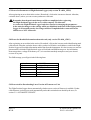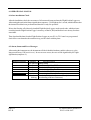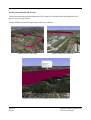
1
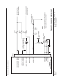
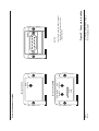
ü
TL-6024
USER`S MANUAL
TL
TL elektronic
Airport, Building 125, Hradec Kralove
503 41, Czech Republic
© Copyright 2007, TL elektronic
Non TSO approved
© Copyright 2007-2008
TL elektronic
All Rights Reserved
Except as expressly provided below, no part of this manual may be downloaded, transmitted, copied,
reproduced, disseminated or stored in any storage medium, for any purpose without the express prior
written consent of the TL elektronic company. Address your questions about the technical information
to TL elektronic. Other information about sale, distribution should be directed to our exclusive
distributors (see World Distributor list on our website).
Producer‘s address:
TL elektronic Inc.
Airport, Building 125,
503 41 Hradec Kralove, Czech Republic
Fax: +420 49 548 23 94 E-mail: [email protected]
Website Address: www.tl-elektronic.com
Please, send your e-mail address to [email protected]
to receive the latest information about the software upgrade.
Send your ideas to [email protected].
We will evaluate your suggestion and provide an update.
Record of revision
Revision
Revision
date
Description
A
15/8/07
Initial Release
B
22/2/08
Language correction
ECO#
Insertion
date
By
--0001
Window is registered trademark of Microsoft Corporation.
All trademarks and registered trademarks are acknowledged.
SchecK® is registered trademark of TL elektronic.
iFamily® is registered trademark of TL elektronic.
sModern® is registered trademark of TL elektronic.
All information in this User‘s manual is subject to change without prior notice.
Page i
Rev. B
TL-6024 USER`S MANUAL
P/N 51-6024-2007
TABLE OF CONTENTS
1. GENERAL DESCRIPTION
1.1. Introduction................................................................................................
1.2. Equipment Description................................................................................
1.3. Technical Specifications..............................................................................
1.4. Limited Conditions......................................................................................
1.5. Limited Warranty.........................................................................................
1.6. Limited Operation........................................................................................
1-1
1-1
1-2
1-3
1-3
1-3
2. INSTALLATION
2.1. Introduction...............................................................................................
2.2. Installation into Aircraft...............................................................................
2.3. Connection to Aircraft Power.....................................................................
2.4. GPS Antenna Installation.............................................................................
2.5. GPRS Antenna Installation...........................................................................
2.6. Alarm Loop Connection and Deactivation Key...............................................
2.7. Main Switch................................................................................................
2.8. SIM Card .................................................................................................
2.9. Instrument Dimensions................................................................................
2-1
2-1
2-1
2-2
2-2
2-2
2-2
2-2
2-3
3. SYSTEM INTERCONNECT
3.1. Pin Function List......................................................................................... 3-1
3.2. TL-6024 Interconnects................................................................................ 3-2
3.3. TL-6024 Connector Location....................................................................... 3-3
4. DESCRIPTION
4.1. General Information.................................................................................... 4-1
4.2. How the Flight Position Logger Works.......................................................... 4-1
4.3. Data collection from the Flight Position Logger TL-6024 and TL-6024_GWG.. 4-2
4.4. Data collection from the Flight Position Logger TL-6024_GWG. only.............. 4-2
4.5. How the Wireless Transfer Works..................................................................4-2
4.6. Approximate Volume of the Transferred Data................................................. 4-2
4.7. Flight Position Logger as Security Device...................................................... 4-3
4.8. Information Provided by Flight Position Logger............................................... 4-3
5. CONFIGURATION
5.1. How to Configure Flight Position Logger....................................................... 5-1
5.2. Main Set-up Functions‘ Description.............................................................. 5-1
5.3. How to Set Parameters in Flight Position Logger........................................... 5-2
5.4. How to Perform Wireless Setting of Parameters in Flight Position Logger....... 5-2
5.5. How to Edit Detailed Information about User................................................ 5-2
5.6. How to Set Interval of Flight Position Logger‘s Connection............................ 5-2
5.7. How to Set Parameters of Flight Position Logger........................................... 5-3
5.8. How to Set Detailed Information about Aircraft............................................. 5-3
5.9. How to Ask for Downloading Latest Version of Firmware to Unit.................... 5-3
6. OPERATIONAL MANUAL
6.1. After-installation Check...............................................................................
6.2. Alarm, Status and Error Messages................................................................
6.3. Data Download in Basic Format...................................................................
6.4. Data Download in KML Format...................................................................
6.5. Data Receive into Email (only version TL-6024_GWG).................................
Page ii
Rev. B
6-1
6-1
6-2
6-3
6-4
TL-6024 USER`S MANUAL
P/N 51-6024-2007
1. GENERAL DESCRIPTION
1.1. INTRODUCTION
This manual describes the physical, mechanical and electrical features and functions of the TL-6024 Flight
Position Logger.
1.2. EQUIPMENT DESCRIPTION
TL-6024 Flight Position Logger records history of the flight including position of the plane, altitude, track
time and ground speed. The information is received via GPS (Global Position Systems) that is fitted in the
TL-6024. The user can download the data from the TL-6024 with his PC using a program that is supplied
with the unit.
TL-6024_GWG Flight Position Logger (as well as TL-6024) records history of the flight including position
of the plane, altitude and ground speed. The information is received via GPS (Global Position Systems)
that is fitted in the unit. However, this version is more sophisticated, as it enables wireless data transfer
about the flight history via GPRS technology (General Packet Radio Service) straight to the user. This
version is equipped with an Quad-band transceiver with worldwide use.
On top of that TL-6024_GWG safeguards the aircraft or its parts such as engine, storage compartment
etc. In this way it works as security equipment similar to e.g. car alarms. It can also send a short message
with information about battery voltage, temperature and position of the aircraft directly to the user’s mobile
phone. Alternatively, this information can be displayed on the user’s PC via an internet browser.
The Flight Position Logger saves the data about the flight position in KML format that can be displayed in
any viewer such as Google Earth.
The Flight Position Logger has memory to store approx. 250 hours of flight history with 1 sec. samples
rate.
1.3. TECHNICAL SPECIFICATIONS
The producer guarantees all stated technical parameters only when the equipment is installed by an
authorized service provider or an aircraft manufacturer.
1.3.1 Physical characteristics
Width
Height
Depth
TL-6024 Weight
TL-6024 Harness
Page 1-1
Rev. B
57mm (2.244 inches)
38mm (1.496 inches)
170mm (6.692 inches) including connectors with cover
0.20 kg (0.44 lbs)
0.05 kg (0.11 lbs)
TL-6024 USER`S MANUAL
P/N 51-6024-2007
1.3.2 General Specifications
Operating Temperature Range
Humidity
Altitude Range
Power Range
Max. Signalization
Power Consumption
Vibration
-20°C to +70°C
95% non-condensing
4600 meters max.
10.0 to 32.0 Volts
30 Volts, 1 Ampere
0.005 Ampere @ 14 VDC - Sleep mode
0.150 Ampere @ 14 VDC - Normal operation
1.58 Ampere @ 14 VDC - Transmition mode
5 to 500 Hz
1.3.3 Long-term Memory
Memory Capacity
Stored Values
Data Saved Endurance
Memory life-time
Samples Rate
32MB
Latitude and Longitude, Ground Speed,
Altitude, Trace Time, Signal Quality, Status
10 years
100 000 storings
1 sec
1.3.4 GPS receiver
Receiver
Number of channels
GPS L1 C/A-code, SPS
12
1.3.5 GSM/GPRS Transceiver
Frequency
GSM Power Class 1
GSM Power Class 4
Data Communication
EMC
Page 1-2
Rev. B
Quad-band 850/900/1800/1900MHz (World wide use)
1W conducted power maximum (30dBm +/- 2 dB),
measured at the antenna port
2W conducted power maximum (33 dBm +/- 2 dB),
measured at the antenna port
TCP / IP protocol, TL elektronic encrypted protocol
FCC Parts 15 & 24, Class B, GSM 11.10, Section 12.2
EN 55022 Class B, FCC Part 22 for GSM 850
TL-6024 USER`S MANUAL
P/N 51-6024-2007
1.4. LIMITED CONDITIONS
1.5. LIMITED WARRANTY
The TL elektronic company warrants this product to be free from defects in materials and manufacture for
three years from the date of purchase. TL elektronic will, at its sole option, repair or replace any
components that fail in normal use. Such repairs or replacement will be made at no charge to the customer
for parts or labour. The customer is, however, responsible for any transportation costs. This warranty does
not cover failures due to abuse, misuse, accident or unauthorized alteration or repairs.
THE WARRANTIES AND REMEDIES CONTAINED HEREIN ARE EXCLUSIVE AND IN LIEU
OF ALL OTHER WARRANTIES EXPRESS OR IMPLIED OR STATUTORY, INCLUDING ANY
LIABILITY ARISING UNDER ANY WARRANTY OF ENCHANT ABILITY OR FITNESS FOR A
PARTICULAR PURPOSE, STATUTORY OR OTHERWISE. THIS WARRANTY GIVES YOU
SPECIFIC LEGAL RIGHTS, WHICH MAY VARY FROM STATE TO STATE.
IN NO EVENT SHALL TL ELEKTRONIC BE LIABLE FOR ANY INCIDENTAL, SPECIAL,
INDIRECT OR CONSEQUENTIAL DAMAGES, WHETHER RESULTING FROM THE USE,
MISUSE, OR INABILITY TO USE THIS PRODUCT OR FROM DEFECTS IN THE PRODUCT.
SOME STATES DO NOT ALLOW THE EXCLUSION OF INCIDENTAL OR CONSEQUENTIAL
DAMAGES, SO THE ABOVE LIMITATIONS MAY NOT APPLY TO YOU.
To obtain warranty service, call the TL elektronic Customer Service (+420 49 548 23 92) for a returned
merchandise tracking number. The unit should be securely packaged with the tracking number clearly
marked on the outside of the package and sent freight prepaid and insured to a TL elektronic warranty
service station. A copy of the original sales receipt is required as the proof of purchase for warranty
repairs. TL elektronic retains the exclusive right to repair or replace the unit or software or offer a full
refund of the purchase price at its sole discretion.
SUCH REMEDY SHALL BE YOUR SOLE AND EXCLUSIVE REMEDY FOR ANY BREACH
OF WARRANTY.
1.6. LIMITED OPERATION
This product is not TSO approved as flight equipment, therefore, the manufacturer
will not be held responsible for any damage caused by its use.
The usage of this product is entirely up to the user's decision.
TL elektronic is not responsible for any possible consequences connected with the operation
of this equipment in the aircraft, particularly if the equipment affected some other
sensitive instruments in the aircraft, or if operation of the equipment infringed laws,
regulations or generally accepted standards in some countries.
Page 1-3
Rev. B
TL-6024 USER`S MANUAL
P/N 51-6024-2007
2. INSTALLATION
2.1 INTRODUCTION
Careful planning and consideration of the suggestions in this section are required to achieve the
desired performance and reliability of the TL-6024.
To use all the features of the TL-6024_GWG it is necessary to insert an activated SIM
Card for data service (GPRS) into the Flight Position Logger. It is not possible to transfer
flight history data wireless without a valid SIM Card.
Please contact your mobile phone operator in regards to their pricelist, terms and conditions and possibility
of receiving GPRS signal in the area, where your aircraft will be used.
2.2 INSTALLATION INTO AIRCRAFT
The Flight Position Logger can be installed anywhere on the aircraft provided that the operation
specifications are followed.
Prior to the installation choose an appropriate place to install the GPS antenna.
GPRS antenna of the TL-6024_GWG version should be placed far enough from the VHF transceiver
antenna so that the undesirable interference is avoided.
During the installation keep in mind that the antenna cable should not be longer than necessary in order to
prevent decrement of the Flight Position Logger’s sensitivity.
The antenna cable should be separate from the rest of the cables in order to prevent possible interference.
If it is necessary to cut the antenna cable short, seek professional advice.
Never fold or curl up the unused antenna cable in a coil. Cutting the antenna cable
should be always done by a professional.
It is advisable to place the equipment away from heating vents or other sources of heat.
2.3 CONNECTION TO AIRCRAFT POWER
TL-6024_GWG version must be permanently connected to battery in the sake of proper operation. You
can connect the Flight Position Logger cable to either battery or terminal block (as close to the battery as
possible). In composite aircraft the GND cable must be also installed as close to the battery as possible.
Since the Flight Position Logger is being continuously charged by battery, it is necessary
to install a wire fuse with the parameters specified on pg. 3-2.
Page 2-1
Rev. B
TL-6024 USER`S MANUAL
P/N 51-6024-2007
2.4 GPS ANTENNA INSTALLATION
If possible install the GPS antenna on the outer top side of the aircraft, so it can receive signals from
satellites without any trouble. Install the GPS antenna at least 50 cm far away from the transceiver and
other antennas.
2.5 GPRS ANTENNA INSTALLATION
If possible install the GPRS antenna on the bottom side of the aircraft, so it is at least 80 cm far from the
ground. In case there is a transponder antenna placed on the bottom side of the aircraft, install the GPRS
antenna at least 50 cm far from this unit.
2.6 ALARM LOOP CONNECTION AND DEACTIVATION KEY
In the version TL-6024_GWG the input from the connector P6001, pin no. 4 needs to be connected in
the way that it creates a grounded loop. It is necessary to use switching contacts or loops through the
connector in the way that in case of disconnecting the connector or opening the door the loop is
disconnected.
The TL-6024_GWG is supplied with a lock (key) switch that has to be connected directly to the pin
no. 4, and its other terminal has to be connected to the ground.
The switch bridges the loop and, in this way, prevents the alarm activation and subsequently prevents
sending information incl. calling the phone number that was set by user.
It is also possible to connect a flashing indicator, which signalizes whether the alarm is active or not, see the
diagram.
2.7 MAIN SWITCH
In the TL-6024 the input from the connector P6001, pin no. 10 must be connected to the connector
P6001, pin no. 8.
In the version TL-6024_GWG the input from the connector P6001, pin no. 10 must be connected to the
Main Switch for proper operation.
2.8 SIM CARD (only version TL-6024_GWG)
Insert the SIM card into the instrument at the side, where the Antenna connector is. To open SIM case
press yellow button that is on the left.
The SIM card has to be activated for GPRS transmission (check with your local GSM
provider) in order to have the Flight Position Logger working correctly.
Page 2-2
Rev. B
TL-6024 USER`S MANUAL
P/N 51-6024-2007
Page 2-3
Rev. A
Mounting Rack Dimension
Bar.
Type.
Volts.
Amps.
Ser. No.
MADE IN CZECH
-20° to 70°C
Temp. Range.
200 grams
Weight.
Frequency. 900/1800/1900MHz
®
Software version. sModern
GPRS MODULE
133 (5.236)
TL-6024
10.0-32.0
1.5@14 Volts
60ANXXXXX
TL ELEKTRONIC
115 (4.527)
146 (5.748)
TL-6024 USER'S MANUAL
P/N 51-6024-2007
Figure 1. Rack Dimension
1. Dimension: mm (INCH)
2. Unit weight: 0.2 kg (0.44 lbs)
3. Mounting Rack & Hardware
weight: 0.05 kg (0.11 lbs)
NOTES:
6 (0.236)
57 (2.244)
38 (1.496)
25 (0.984)
3.1 PIN FUNCTION LIST
Pin
1
2
3
4
5
6
7
8
9
10
11
12
13
14
15
Page 3-1
Rev. B
Pin Name
Aircraft ground
Alarm and Status Light
Ground for PC communication (RS-232)
TXD to PC (RS-232) Out
iFamily® communication ISCL
Alarm input
Do not connect!
Aircraft power
Aircraft ground
Main Switch
RTS from PC (RS-232)
RXD from PC (RS-232)
iFamily® communication ISDA
Do not connect!
Aircraft power
I/O
-Out
-Out
I/O
In
-In
-In
In
In
I/O
-In
TL-6024 USER`S MANUAL
P/N 51-6024-2007
Page 3-2
Rev. A
TL-6024
POSITION LOGGER
4
12
3
11
6
ALARM INPUT
RS 232 TX
RS 232 RX
GROUND
RS 232 RTS
10
2
ALARM STATUS LIGHT
MAIN SWITCH
1
9
8
15
AIRCRAFT GROUND
AIRCRAFT GROUND
10-32V AIRCRAFT POWER
10-32V AIRCRAFT POWER
P6001
(note. 1)
0.25A
FUSE
0.25A
FUSE
3A
FUSE
1. Alarm is activated when the grounded
alarm input No.6 is disconnected
NOTES:
RIGHT
door
Circuit in any connector
to the engine
AIRCRAFT POWER
(MAIN SWITCH)
BATTERY (+) POL
(AIRCRAFT POWER)
TL-6024 USER'S MANUAL
P/N 51-6024-2007
Figure 2. Accessories interconnect
DEACTIVATION
KEY
LEFT
door
D-SUB 9 pins
(female)
ALARM activate indication
(Red Light Emission Diode)
1
2
Accessories Interconnect
9
8
7
6
3
4
5
Page 3-3
Rev. A
SIM
case
GSM/GPRS
antenna
GPS
antenna
Version TL-6024_GWG
GPS
antenna
Version TL-6024
View of connectors location
1
9
TL-6024 USER'S MANUAL
P/N 51-6024-2007
Figure 3. Connectors location
1. Secure the incoming leads to prevent
their effect on the connector in the
vertical direction.
NOTES:
15
8
P6001
4. DESCRIPTION
4.1 General Information
The Flight Position Logger can record basic flight information such as position of the plane, ground speed,
altitude and track time and other information.
This information can be used for:
- checking students’ navigation abilities while performing solo navigation flights
- posible disagreement, where the aircraft did or did not enter controlled airspace (CTR, TMA)
- in case of a complaint, for determination whether the aircraft was in the incriminated area
- flight billing at flight schools (it is possible to have an automated billing in the version
TL-6024_GWG)
On top of that TL-6024_GWG version can provide information about condition of the battery,
temperature of the aircraft, threat of stealing the aircraft or its parts, and much more.
The information can be transferred directly to the user’s mobile phone. Alternatively, the information
about aircraft can be displayed on the user’s PC via an internet browser.
4.2 How the Flight Position Logger Works
When connecting the Flight Position Logger to a power supply or when switching on the Main Switch
(in case of the TL-6024_GWG) the inner circuits and GPS receiver are activated. In case the ground
speed limit (that can be set in the Setup Menu, see paragraph 5-2) is exceeded, the Flight Position Logger
starts recording the position of the plane and also other values. The recording is processed once a second.
If the flight lasts longer than 10sec., the record is considered as valid and the instrument continues in
recording. As soon as the ground speed falls under the set limit and this lasts longer than 30sec. the flight is
considered as finished and the record is finished at the point, when the ground speed fell under the set limit.
4.3 Data Collection from the Flight Position Logger TL-6024 and TL-6024_GWG
To retrieve the measured data from the TL-6024 connect the instrument to a PC and use the
TL Control.exe software that is supplied with the instrument. Start the program, click on “Load” and
choose a file, where the data will be stored on the disc. In case you choose a different file to the one you
have used previously, all the flights will be downloaded again and saved in the new file.
Each flight is saved in the chosen file in TXT or KML format that can be displayed in a viewer such as
Google Earth etc.
Page 4-1
Rev. B
TL-6024 USER`S MANUAL
P/N 51-6024-2007
4.4 Data Collection from the Flight Position Logger TL-6024_GWG only
You can download the measured data from the TL-6024_GWG wireless via GPRS technology. There is
also possibility to download the measured data by connecting the instrument to a PC; follow the steps
described above.
Wireless transfer of the flight history is a highly sophisticated system and it is described below.
4.5 How the Wireless Transfer Works
As soon as the aircraft lands, the Flight Position Logger connects to the networks of provider via GPRS
technology and TCP/IP protocol that is encrypted with the TL elektronic server. On grounds of this
protocol the Flight Position Logger transfers basic flight information such as position and time of take off,
position and time of landing, and length of the flight to the TL elektronic server. The information (incl. kml
file showing the start and finish of the flight) is automatically processed and sent to the user’s email address.
The user receives this information generally within one minute. However, this depends on the supplier of
GPRS service and GPRS signal quality at the landing site.
If the user requires information about the whole flight record, it is possible to download it with the help of
the TL elektronic website. The client just needs to fill in his user name, password and then chose the
flight(s) they need. There is also a possibility of an automatic data transfer, see section 5-2 “TRANSMIT
MODE”.
On grounds of internal organisational regulations (QC-101), TL elektronic guarantees
that no sensitive data is stored on the GPRS server of TL elektronic and the data is
deleted immediately after sending it to the user.
4.6 Approximate Volume of the Transferred Data
Since the GPRS service (in regards to the transferred data volume) is being provided on a payment in
some countries, there are approximate figures stated below:
Data transfer after landing (basic flight information such as position and
time of take off, position and time of landing, flight time)
Data transfer of one flight that lasts approx. 1 hour (complete flight
information with 1sec. sampling)
Page 4-2
Rev. B
ca. 500 Byte
ca. 100 kByte
TL-6024 USER`S MANUAL
P/N 51-6024-2007
4.7 Flight Position Logger as Security Device
An unique feature of the Flight Position Logger is the security
function that can secure the whole aircraft or some of its parts,
such as storage compartment etc.
The Flight Position Logger is provided with a voice output that
will call the phone number you have set and will inform you in
several languages that somebody is trying to steal your aircraft or
some of its parts. After that, the Flight Position Logger will send
this information in an SMS message to your mobile phone or in
an e-mail to your PC.
This function is controlled by the pin no. 6
(see section 2.5)
Provider
Incoming call:
'
My aircraft OK-CZE
1
2
3
4.8 Information Provided by Flight Position Logger
It is also possible to use the Flight Position Logger for detecting
the position of the aircraft, the information about its temperature,
the condition of the battery and other information described in
the section 5.7.
Information is transferred in intervals that are set in the unit, see
section 5-2 „CONNECTION PERIODE”.
Provider
Aircraft: OK-CZE
Position: Airport, Prague
Temperature: 26°C
Battery: 12.6V
Signal quality: 65%
Alarm status: OK
1
Page 4-3
Rev. B
2
3
TL-6024 USER`S MANUAL
P/N 51-6024-2007
5. CONFIGURATION
5.1 How to Configure Flight Position Logger
All settings are achived with the help of the TL-control.exe or via internet browser ( only version GWG).
5.2 Main Set-up Functions‘ Description
The table of the equipment configuration steps is shown below (Initial - firmware version 1.0).
0
1
2
3
4
5
6
7
8
9
10
11
12
PASSWORD
Enter your password.
CONNECTION PERIODE Set the interval for connecting the TL-6024 to the server
of the TL elektronic company.
TRANSMIT MODE
Select DISABLE = do not send the data after landing or
select SHORT = send short message about the place and time
of take off, excluding information about the whole flight course
or select FULL = send the short message and the information
about the whole flight course after landing
ALARM FUNCTION
Select ENABLE = in case of the disconnected Alarm loop,
the TL-6024 will send an SMS message and call the set
mobile phone number to inform on possible stealing of your
aircraft. Or, select DISABLE = the loop will not be checked.
STATUS MESAGE
Select ENABLE = always before connecting the TL-6024 to
the server of the TL elektronic company, the information on
the position, battery condition etc. will be sent to the set
mobile phone number. Or, select DISABLE = status message
will not be sent. The interval for sending the STATUS
MESSAGE is according to the „CONNECTION
PERIODE“ set by you. The information from the STATUS
MESSAGE are available on the server of the TL elektronic
company anytime the TL-6024 is connected.
AIRCRAFT TYPE
Enter type of aircraft.
AIRCRAFT ID
Enter aircraft identification number.
AUTOMATIC UPDATE
Select ENABLE = an automatic firmware update of the Flight
Position Logger will be always performed DISABLE = an
automatic firmware update will be never performed
YOUR MOBILE NUMBER Enter your mobile phone number.
SIM CARD PIN
Enter PIN code of your SIM card.
NO. OF SMS CENTER
Enter the number of the SMS center of your operator
(get this information from the provider).
YOUR EMAIL
Enter the e-mail address to which the TL elektronic company
can send you the data downloaded from your instrument.
VOICE WARNING
Enable or disable the voice warning about operation and
errors of the TL-6024 into your headphones
(Only with use of our Intercom TL-2424 or Voice Module).
All information on this page is subject to change without prior notice. Download the latest
version of the manual from www.tl-elektronic.com and compare with you version of firmware.
Page 5-1
Rev. A
TL-6024 USER`S MANUAL
P/N 51-6024-2007
5.3 How to Set Parameters in Flight Position Logger
The whole configuration can be set on TL Control.exe program that is supplied with the instrument.
After starting TL Control.exe program, click on “Config” icon and then set all the parameters, see 5-2.
5.4 How to Perform Wirelless Setting of Parameters in Flight Position Logger (only version
TL-6024_GWG)
First of all, it is necessary to register the Flight Position Logger in the GPRS server of the company
TL elektronic.
Fill in the form on the website address:
http://www.tl-elektronic.com/goto.php?goto=gprs_en_login.php
Login: fp
Password: fp
and follow the next instructions.
If you own more than one Flight Position Logger that information which is appropriate to individual units
can be view simultaneously. To activate this in the registration form enter the assigned registration number
of any Flight Position Logger and register the other Flight Position Logger in the section "Registration of
other Flight Position Logger", which is to be found in the detailed information about the user.
5.5 How to Edit Detailed Information about User (only version TL-6024_GWG)
After registering, click on the icon next to the name of the aircraft's user. After that, a window shows
where you have to fill in the e-mail address, to which the Flight Position Logger will send the error
messages and other information. Here you can also add or delete the Flight Position Logger or edit
some other information.
5.6 How to Set Interval of Flight Position Logger‘s Connection (only version TL-6024_GWG)
The interval for the frequency of connecting the Flight Position Logger with the server of the company
TL elektronic can be set from 30 minutes up to 1 month.
Remember that if you set a longer interval, the response to your request for downloading
the data will depend on this interval. This interval does not affect, however, the immediate
response in the case that somebody attempts to steal your aircraft or some of its parts.
You should also remember that a short interval may cause faster discharge of your battery.
Page 5-2
Rev. B
TL-6024 USER`S MANUAL
P/N 51-6024-2007
5.7 How to Set Parameters of Flight Position Logger (only version TL-6024_GWG)
After registering on our website in the section „Download“, click on the icon next to the unit. After that,
a window shows, where you can set some parameters of the unit.
Remember that the performed changes will be accomplished after registering
the Flight Position Logger in the server of the company TL elektronic.
As soon as the Flight Position Logger loads the requests for changing the parameters
in the unit, the changes or the settings will be accomplished in the unit. If the Flight position
Logger is off (stand by mode), the changes will be accomplished after connection to the
GPRS server of TL elektronic.
5.8 How to Set Detailed Information about Aircraft (only version TL-6024_GWG)
After registering on our website in the section „Download“, click on the icon next to the identification mark
of the aircraft. After that, a window shows where you have to fill in the e-mail address, to which the Flight
Position Logger will send the information and the data from the instruments. It is also necessary to enter the
phone number, which the Flight Position Logger will call and send SMS messages to - the information
about temperature, voltage of the battery etc., or in case that somebody atempts to steal your aircraft
or some of its parts.
The SMS message you will get is in the following form:
Aircraft:
Position:
Temperature:
Battery:
Signal quality:
Alarm status:
OK-CZE
Airport, Prague
26°C
12.6 Volts
65%
OK
5.9 How to Ask for Downloading Latest Version of Firmware to Unit
The Flight Position Logger detects automatically whether a new version of firmware is available. Update
of the firmware is always processed automatically unless this action has been denied by the user, see
section 5-2 “AUTOMATIC UPDATE”.
Page 5-3
Rev. B
TL-6024 USER`S MANUAL
P/N 51-6024-2007
6. OPERATIONAL MANUAL
6.1 After-installation Check
After the installation, check the correctness of all connected inputs and turn the Flight Position Logger on.
After turning the unit on the Status signalization (output no. 2) will light up for 1 second, which indicates that
the internal check has been performed and the unit is ready for operation.
Prior to the first take-off with newly installed Flight Position Logger; set the speed value, which activates
recording into the Flight Position Logger’s memory, at 5km/h (3kts) and then taxi on a runway for about
one minute.
Then download the data from the Flight Position Logger on your PC via TL Control.exe program and
check if the record matches the actual taxiway you have done with the plane.
6.2 Alarm, Status and Error Messages
After turning the instrument on, the instrument will check both the hardware and the software (e.g. the
long-term memory, GPS receiver etc.). In case an error occurs, the error will be signalized by the Light
signalization (output no. 2).
Blinking Frequency
- - .. .. ..
... ... ...
.... .... ....
..... ..... .....
............................
Page 6-1
Rev. B
Number
2sec interval
2x
3x
4x
5x
Continuous
blinking
Error Description
Alarm Armed
Insufficient Signal for GPS Receiver
Error in the Setting Memory
Error in the Operating Data Memory
Error in the Data Memory
Data storing into Memory is Running
Bootloader Mode (the instrument is ready for
downloading of the new firmaware)
TL-6024 USER`S MANUAL
P/N 51-6024-2007
6.3 Data Download in Basic Format
You can download data from the instrument via TL Control.exe in basic format and this can be then
processed upon your requirements.
Sample of the TXT protocol is below
-------------------------------------------------------------------------------TL-6024
Log
Created: 23.04.2006 07:43:30 (UTC)
TL-Control
ver.1.6.8
TL-elektronic
TL-6024
ver.1.0.0
--------------------------------------------------------------------------------------------------------- F L I G H T
R E P O R T ---------------------------
Date and time of start flight: 23.04.2006 07:42:01 (UTC)
Duration
00:00:04
Flight identificator:
57
Number of lines:
5
|---------|----------------------------- |-----------|----------|------ |-------|
|
Time |
Possition
| Gnd Speed | Altitude | Sat. |Status |
|
UTC |
Latitude
|
Longitude |
[km/h] |
[m]
| Used |
|
|---------|--------------|--------------|-----------|----------|------ |-------|
07:42:01
5014.3543,N
01550.5726,E
80
241
7
*T*
07:42:02
5014.3552,N
01550.5734,E
85
248
7
07:42:03
5014.3568,N
01550.5742,E
88
256
7
*B*
07:42:04
5014.3575,N
01550.5749,E
85
248
7
*C*
07:42:05
5014.3584,N
01550.5754,E
80
241
7
*L*
--------------------------- E N D
O F
R E P O R T ----------------------------
Symbols in the column “Status”:
*T* - Take off
*L* - Landing
*B* - Break
*C* - Continuation in the flight after break
Page 6-2
Rev. B
TL-6024 USER`S MANUAL
P/N 51-6024-2007
6.4 Data Download in KML Format
You can download data from the instrument via TL Control.exe in format, which is designed for a web
browser such as Google Earth.
Sample of KML protocol in Google Earth web browser is below:
Sample of track of the flight
Sample of the place of take-off
Sample of information about altitude, ground speed, time on track
Page 6-3
Rev. B
TL-6024 USER`S MANUAL
P/N 51-6024-2007
6.5 Data Receive into Email (only version TL-6024_GWG)
Following the setting, see section 5.2 “Transmit Mode”, you will receive a short email message after the
flight. The message will inform you about the place and time of take-off and landing of the aircraft,
alternatively about the whole flight course. The email always includes KMZ file, which can be viewed on a
web browser e.g. Google Earth.
In case you have not activated data transfer after each flight, you can require record of the flight on our
website at any time; go to “Download” or to this website address:
http://www.tl-elektronic.com/fp.htm
Sample of a short email message:
Dear User of TL elektronic equipment,
In the attachment we are sending you information on current position of your
aircraft, which you have activated through our web sites.
Aircraft: OK-JHC Flight ID: 48
------ T a k e - o f f --------------------------------------------------------Date of take-off (UTC):
2007/04/05
Time of take-off (UTC):
8:04:31
GPS position of take-off:
49`44'26.44"N,14`38'29.12"E
Take-off airport:
LKBE
------ L a n d i n g ----------------------------------------------------------Date of landing (UTC):
2007/04/05
Time of landing (UTC):
8:58:00
GPS position of landing:
50`14'49.98"N,15`50'58.39"E
Landing airport:
LKHK
----------------------------------------------------------------------------------Total flight time:
0:53:29
----------------------------------------------------------------------------------Thank you for using wireless GPRS service by TL elektronic.
----------------------------------------------------------------------------------If you are not the intended recipient please delete this e-mail immediately.
Any unauthorized copying, disclosure or distribution of the material in this
e-mail is strictly forbidden.
----------------------------------------------------------------------------------Copyright 2007 – TL elektronic, generated on: 05.04.2007 09:02:08
Page 6-4
Rev. B
TL-6024 USER`S MANUAL
P/N 51-6024-2007
This page intentionally left blank
Page 7-1
Rev. B
TL-6024 USER`S MANUAL
P/N 51-6024-2007