1
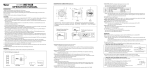
Wireless Video Door Phone
Installation and Operating Instructions
PLEASE READ THESE INSTRUCTIONS CAREFULLY BEFORE USING THIS PRODUCT
AND KEEP THIS MANUAL FOR FUTURE REFERENCE.
CONTENTS
INTRODUCTION .............................................................................................. 2
IMPORTANT SAFETY PRECAUTIONS .....................................................................2
KNOWING YOUR DEVICES ............................................................................ 3
DOOR UNIT..............................................................................................................3
ANSWERING UNIT................................................................................................... 4
KNOWING THE SCREEN ICONS .............................................................................5
MOUNTING THE DOOR UNIT .................................................................................. 7
KNOWING THE MAIN MENU......................................................................... 10
ADVANCED SETTINGS ................................................................................. 11
CAMERA SETUP ....................................................................................................11
RECORDER SETUP ...............................................................................................12
SETUP MASKING AREA ...................................................................................14
EVENT LIST ...........................................................................................................15
DATE ................................................................................................................15
TIME .................................................................................................................17
FILE ..................................................................................................................19
SYSTEM SETUP ....................................................................................................20
ALARM BUZZER ....................................................................................................22
PAN TILT ZOOM ..................................................................................................... 23
SCAN ACTIVATED CAMERAS................................................................................24
MEMORY CARD OVERWRITE ...............................................................................25
PC PLAYBACK SOFTWARE.......................................................................... 26
SEC24 MEDIA PLAYER INTRODUTION
.........................................................................26
SOFTWARE INSTALLATION .................................................................................. 27
PLAYBACK RECORDED FILE(S) ........................................................................... 29
ADDING ADDITIONAL CCTV CAMERA .................................................................31
PRODUCT SPECIFICATION .......................................................................... 32
STORAGE MEDIA MANAGEMENT .........................................................................32
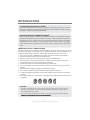
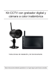
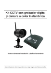
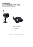
WHAT YOU GET
• Digital Wireless 7" Touch LCD Answering Receiver X1
• Digital Wireless Door Unit X1
• 12V/1A Power Adaptor for the Door Unit X1
• 5V/1A Power Adaptor for the Answering Receiver X1
• DC Power Cable X1
• Unlock Connection Cable X2
• Water Resistant Plug X2
• Mounting Bracket X1
• Mounting Pack X1
• Anti-Thief Screwdriver X1
• PC Player Software CD X1
1
INTRODUCTION
PLEASE READ BEFORE YOU START
Always use discretion when installing CCTV equipment, especially when there is perceived
policy. Enquire relevant local regulations applicable to the lawful installation of video recording/
surveillance. Third party consent may be required.
WIRELESS DEVICES OPERATING RANGE
I
Ensure the signal reception viewed from the wireless camera(s) is the best possible reception
between the camera(s) and the Wi-Fi router. If necessary, reduce the distance between the
camera(s) and the Wi-Fi router to improve overall system performance. Wireless Color Camera
Recordable CCTV Kit operating on a secure digital 2.4GHz frequency which could greatly
reduce interference from product such as wireless routers, cordless phones or microwave
ovens.
IMPORTANT SAFETY PRECAUTIONS
Damages caused by non-compliance with this operating manual will void the warranty! We will
not assume any liability for damages to items or persons caused by improper handling or noncompliance with the safety notices! Any warranty claim will be null and void in such cases.
1. Do not drop, puncture or disassemble the camera; otherwise the warranty will be voided.
2. Avoid all contact with water, and dry hands before using.
3. Never tug on the power cords. Use the plug to unplug it from the wall outlet.
4. Do not expose the camera to high temperature or leave it in direct sunlight. Doing so may
damage the camera or cause camera temporary malfunction.
5. Use the devices with care. Avoid pressing hard on the camera body.
6. For your own safety, avoid using the camera or power off the camera when there is a storm or
lightning.
7. Remove the power adapter during long periods between usages.
8. Use only the accessories and power adapters supplied by the manufacturer.
9. To meet the regulations pertaining to parental responsibility, keep the devices out of the reach
of infants.
10. Check power cables, do not get crushed or damaged by sharp edges whenever the devices are
in operation.
CAUTION
•This product is designed with built-in high sensitivity microphone. Please keep the door unit away from
the answering unit at least 3 to 5 meters, otherwise continuously howling will occur. Please volume
down if short distance use is needed.
•Do not insert or remove SD Card when the system is in operation. This may cause system malfunction.
e.
2
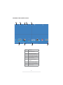
KNOWING YOUR DEVICES
DOOR UNIT
Item
Function
Item
1
Antenna
9
Dry Contact Output A
Function
2
Speaker
10
3
IR LED
Dry Contact Input
(for DC Power Cable)
4
EDS
11
Dry Contact Output B
5
Call Button
12
Power Adaptor
6
Microphone
13
DC Power Cable
7
Pairing Key
14
Unlock Connection Cable
8
Battery Compartment
Note:
1. The door unit can operate in Battery mode or DC mode. In Battery mode, it requires 6 x
AA batteries to operate (which are not included).
2. Low battery may cause system malfunction. Please replace battery in time.
3
ANSWERING UNIT
Item
Function
Item
Function
1
Wirelless Signal Indicator
7
Flip-out Stand
2
Power Indicator
8
Micro SD Slot
3
Microphone
9
Reset
4
Antenna
10
AV Out Jack
5
Power Button
11
Adaptor Plug
6
Speaker
Note:
When using A/V cable connecting the receiver to TV, the display on receiver will not be
available and answering visitor function will also be turned off until disconnecting A/V cable
from the receiver.
4
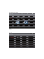
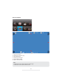
KNOWING THE SCREEN ICONS
Item
Function
1
Channel Number
2
Active Voice Channel
3
Wireless Signal Strength
4
Camera Battery Capacity
5
Channel Status
6
Recording Countdown
Indicator
7
Receiver Battery Status
8
System Time Information
9
Record Status
5
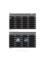
System Tray Icon
Icon image
Name
Function
System Tray
System Tray-Hide & display tray icon
Channel Display
Press to switch display channel
Two Way Audio
Press to start/stop communication.
Door Control
Press to open the door (Dry Contact B)
Gate Control
Press to open the gate (Dry Contact A)
Volume
Press to adjust receiver volume
Press to start/stop recording
Note:
1. Record function cannot be stopped unless the
countdown OSD completes
Record
Setup
2. Receiver starts to record for 1 minute when a visitor
presses the doorbell. If users answer the visitor, one
more minute will be recorded.
3. Users cannot switch channel to another camera
when recording function is active.
Press to enter setup menu
CAUTION
. By default, the monitor screen will be ALWAYS ON. If you want to save power
consumption, please setup the idle mode in 'System Setup' sub-menu. ('System Setup' >
'Power Saving' > 5Minutes/10Minutes/ALWAYS ON).
6
MOUNTING THE DOOR UNIT
BEFORE YOU START
• Before installing the door unit, please first check to make sure the location is suitable for the
installation.
• To avoid possible damages, the installation location should free from excessive moisture, dust
and vibration. For optimum transmission performance, avoid installing the door unit directly or
near metallic building materials. Excessive numbers of network access points, such as Wi-Fi
routers will also reduce the wireless transmission performance.
• There are two ways to supply power to the door unit, either via batteries or DC power. The battery
power mode offers pure convenience, especially when no power source near by the installation
location. If door unlock function (3rd party door lock with own power supply required) is required,
please install the door unit via DC power mode only. Please note that both sets of dry contacts for
the door locks (not supplied) do not supply any power.
Installation via Battery Power Mode
1. First insert six AA batteries (not included) according to the
polarity (+/-) indicator on the door unit.
2. Optional: The door unit has been paired to the receiver by
factory default. If you need to pair the door unit to the system
Pairing
Key
again, please go to "Advanced Settings / Camera Setup" for
more details.
3. Door unit is now ready for use.
Put in 6x “AA” 1.5V batteries
Step1
Use the sunshield as a template
to drill 4 suitable holes and attach
the sunshield to the wall with the
screws and wall plugs (supplied).
Step2
Install the back panel (with batteries
inserted) to the door unit with the
correct screws (supplied).
7
Step3
Position the door unit into
the sunshield and finish
the installation with the
two anti-theft screws
(supplied).
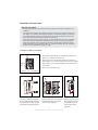
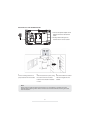
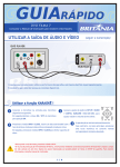
INSTALLATION VIA DC POWER MODE
Dry Contact A - Related icon
Adaptor connect to DC Jack
Dry Contact B - Related icon
Input
A. 4-Wire Type Connection Diagram
Power
B. 2-Wire Type Connection Diagram
Power
1. Remove the back cover of door unit.
2. (Optional) The door unit supports two types of third-party locks, 4-wire type and 2-wire type (please
note the door unit do not supply the power to the 3rd party locks). If you want to control the door
lock via the receiver, please follow the wire connection method in the figure above.
r wire to the terminal block with
"DC+" symbol. Connect the Black power wire to the terminal block with "DC-" symbol. Then plug
the power adapter to the DC IN jack and wall outlet.
4. Optional: The door unit has been paired to the receiver by factory default. If you need to pair the
door unit to the system again, please go to "Advanced Settings / Camera Setup" for more details.
5. Install the door unit in proper location.
Step1
Use the sunshield as a template
to drill 4 suitable holes and attach
the sunshield to the wall with the
screws and wall plugs (supplied).
Step2
Install the back panel to the door
unit with the correct screws
(supplied).
8
Step3
Position the door unit into
the sunshield and finish the
installation with the two
anti-theft screws (supplied).
MOUNTING THE THE ANSWERING UNIT
1. Connect the power adapter to the
DCIN jack and the nearest wall
outlet.
2. Press [Power Button] for two
seconds to turn on the receiver.
1
Fix the mounting bracket to a
proper location with the screws.
2
After the bracket is in place, hang
the recever onto the mounted
bracket in the direction indicated
3
Side view of after the receiver
has been hanged onto the
bracket.
in 2 & 3.
Note:
When using A/V cable connecting the receiver to TV, the display on receiver will not be
available and answering visitor function will also be turned off until disconnecting A/V cable
from the receiver.
9
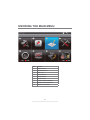
KNOWING THE MAIN MENU
Item
Function
1
CAMERA SETUP
2
RECORDER SETUP
3
EVENT LIST
4
SYSTEM SETUP
5
ALARM BUZZER
6
PAN TILT ZOOM
7
SCAN ACTIVATED CAMERAS
8
MEMORY CARD OVERWRITE
9
RETURN TO LIVE VIEW
10
ADVANCED SETTINGS
CAMERA SETUP
Item
1
Function
CH1 (Doorphone 1)
- Pair
- Brightness
CH 2, CH3, CH4
2-4
5
(CCTV Camera)
- Pair
- Brightness
- Camera On/Off
Return to Setup Menu
In this section you can pair and adjust the brightness setting for
door unit and optional CCTV cameras (for more information on
where to purchase the additional CCTV camera please contact
vendor).
Please note, channel 1 is dedicated to door unit only. Additional
CCTV cameras are to be paired to channel 2, 3 and 4.
By default the video of the door unit is in full screen mode and
with additional CCTV cameras added to the system the receiver
display will automatically be in quad mode.
For any reason you need to re-pair the door unit to the receiver,
please first tap on channel 1 and select pair. You will have 30
seconds to press the pair-key, which is located in the back of the
door unit (see "mounting the door unit" section for more detail).
"Pairing Fail" will be displyed if pair-key not pressed within the 30
seconds period (please make sure the door unit is correctly
powered), tap on pair icon to re-initiate the pairing process again.
11
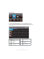
RECORDER SETUP
1. Each motion recording time is 2 minutes.
3. Users can stop manual record by themselves. Recording will be stopped after 10 minutes if
users do not stop it.
Item
1
2
Function
Record Schedule (24 hours)
- M = Motion
- S = Schedule
- X = Manual
Motion Detection Sensitivity
- LV 1 / LV 2 / LV 3
Memory Card Erase
- Tap to start for matting
3
Setup Masking Area
4
- 8 x 6 Grid
5
Return to Setup Menu
12
13
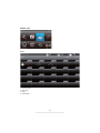
SETUP MASKING AREA
1. Save & Exit
2. Block grid
3. Unblock grid
14
EVENT LIST
DATE
1.
2.
3.
4.
Previous Page
Next Page
Return
Folder (Date)
15
Press folder and hold on 2 seconds
5. Delete
6. Cancel
Date Folder
16
TIME
1. Return
2. Folder (Time)
Press folder and hold on 2 seconds
3. Delete
4. Cancel
17
File
5. Previous Page
6. Next Page
7. Return
8. File
9. Delete
10. Cancel
18
FILE
1. Tray Icon Expand/Hide
2. Backward
3. Pause/Play
4. Forward
5. Display Channel
6. Stop Playback and Back to Folder
7. Time Stamp Information
8. Channel Status
9. Play Status
19
SYSTEM SETUP
Item
Description
1
Date and Time
- Adjust Year/Month/Date/Hour/
Minute
2
TV Output
- NTSC/PAL
3
Power Saving
- Screen off After 5 Minutes Idle
- Screen off After 10 Minutes Idle
- Screen Always On
4
Multi Channels Idle Display
- QUAD Display
- Doorphone Display
- 10 Sec. Scan with Doorphone Display
- 10 Sec. Scan without Doorphone Display
5
Default (Language Setting)
- English (Default)
- Français
- Deutsch
6
Return to Setup Menu
20
TV Output Tip:
Users should choose right TV output format to match NTSC or PAL TV. Receiver output will be
invisible when TV output port is connected.
Power Saving Tip:
Set receiver panel turn off time to save the power.
Multi Channels Idle Display Tip:
Set sequential switch time interval of all active channels.
Default Tip:
Default setting will be executed when language setting is changed.
21
ALARM BUZZER
Alarm Buzzer setting of receiver.
22
PAN TILT ZOOM
1.
2.
3.
4.
5.
6.
Channel Information
Digital Zoom Information (2X)
Zoom Mode Status
Wireless Signal Strength
Receiver Battery Status
System Time Information
Note:
1. Red triangle mark is used to adjust the visible range.
2. Black return mark is used to exit the mode.
23
SCAN ACTIVATED CAMERAS
Enter sequential switch mode of all active channels.
System Tray Icon
1. Channel Information
2. Scan Activated
Cameras Mode
3. Wireless Signal
Strength
4. Receiver Battery
Status
5. System Time
Information
6. System Tray Icon
7.Exit Scan Mode and
Back to Setup Menu
24
MEMORY CARD OVERWRITE
25
PC PLAYBACK SOFTWARE
Sec24 MEDIA PLAYER INTRODUCTION
The Sec24 Media Player is specially designed for security playback the unique video format generated
from the system after detecting unusual movements from the site where the camera of the system is
installed.
5
1.
2.
3.
4.
5.
6.
Channel 1 Playback Screen
Channel 2 Playback Screen
Channel 3 Playback Screen
Channel 4 Playback Screen
Playback Progress Bar
Play
7. Pause
8. Stop
9. Fast Rewind
10. Fast Forward
11. Load Recorded File(s)
12. Channel Enable / Disable Select
26
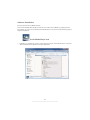
Software Installation
Insert the CD into the CD-ROM of the PC.
Click on MY COMPUTER, double click on the drive where the CD-ROM is assigned by the PC
(for example: E;\) and you will find the Sec24 Media Player icon. Please read the following steps to
complete installation.
Sec24 Media Player icon
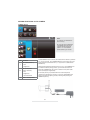
1. If Window 7 is running on your PC, please right click on icon “Sec24 Media Player” and select
“Run as administrator” option first to begin installation.
27
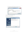
Note: The following error message will appear if you did not select “Run as
administrator” option first before starting the installation.
2. Double click the icon to start the installation process.
3. Click “Next” to continue the installation.
4. When the installation is completed, click “Finish” to exit the install wizard.
\
28
Playback Recorded File(s)
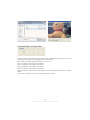
1. Double click the Sec24 Media Player icon on the desktop to start the software.
Sec24 Media Player icon
2. Click on “Load” to import and playback previous recorded files (SNX files) already stored on
your PC.
Note: You will first need to save the files from the Micro SD card to the PC first.
If your PC has a memory card reader then use the supplied memory card adaptor.
29
Channel Disable / Enable Select
During playback, all four channels can playback at once, including audio. For privacy concern, user
can select specific channel(s) for playback, with or without audio.
Select Audio to playback audio from channel 1 or 2 or 3 or 4
Select 1 to playback video image from channel 1
Select 2 to playback video image from channel 2
Select 3 to playback video image from channel 3
Select 4 to playback video image from channel 4
When more then one channel selected for playback, system will display playback screen in QUAD
format.
Audio is only synchronized to the video channel triggered by motion.
30
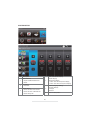
ADDING ADDITIONAL CCTV CAMERA
CAMERA SETUP
Note:
A. Channel 1 is dedicated to
door unit only.
B. Only use camera specified
compatibility. NOT all CCTV
cameras will work with this
system. For more details
please contact your vendor.
Item
1
Function
CH1 (Doorphone 1)
- Pair
- Brightness
CH 2, CH3, CH4
2-4
5
(CCTV Camera)
- Pair
- Brightness
- Camera On/Off
Return to Setup Menu
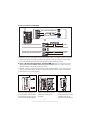
To add additional CCTV camera, first make sure the camera is powered
on. On your receiver, go to CAMERA SETUP in the system menu and
select preferred camera channel 2, 3 or 4 (channel 1 is dedicated for
DOOR Unit).
After selecting preferred camera channel (2, 3 or 4), tap PAIRING icon
to initiate the camera pairing process, you will have 30 seconds to
press the CAMERA's pair-key, which is located on the power cable
of the camera (see image below).
If camera's pair-key not pressed within the 30 seconds period,
"Pairing Fail" will display on receiver, in this case, tap PAIRING icon
again to re-initiate the pairing process, following with pressing the
CAMERA's pair-key.
31
PRODUCT SPECIFICATION
Maximum Unit(s)
Door Unit
Receiver Unit
1
1
Communica on Range
200 Meters (Line of Sight)
View Angle
IR LED Wave Length
Resolu on
H: 90°±-3; V: 60°±-3
N/A
850nm
N/A
640 x 480 (VGA)
800 x 480 (LCD)
Single Channel 640 x 480 (VGA)
Mul ple Channel 320 x 240 (QVGA) per Channel
IR Night Vision Range
2 Meters
N/A
Min. Illumina on
0 ~ 8Lux
N/A
Max. Opera ng Current
120mA
800mA
N/A (Dry Contacts)
N/A
135mA per Pulse
N/A
N/A
400mA
Door Lock Voltage
Max. Door Lock Current Handling
Ba ery Charging Current
Opera ng Temperature/Humidity
-10°C ~ 40°C / 0% ~ 80%
STORAGE MEDIA MANAGEMENT
SD Card Capacity
Recording Time
1G
110 Minutes
2G
219 Minutes
8G
875 Minutes
16G
1750 Minutes
32G
3500 Minutes
32