1
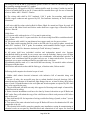
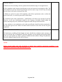
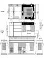
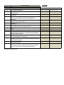
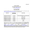
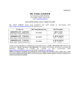
Annexure-I
OIL INDIA LIMITED
(A Government of India Enterprise)
P.O. Duliajan-786602, Assam, India
E-mail: [email protected]
INVITATION FOR BID
LOCAL COMPETITIVE BID
OIL INDIA LIMITED invites Local Competitive Bid (LCB) through its e-procurement portal
https://etender.srm.oilindia.in/irj/portal for the following items:
Tender No
Bid Closing/
Opening Date
Item & Qty
SDI8464P16 DT:05.09.2015
15.10.2015
TRUCK FOR MOBILE STEAM GENERATOR
SDI8469P16 DT: 07.09.2015
29.10.2015
CREW CABIN
SDI8467P16 DT: 07.09.2015
29.10.2015
BUNK HOUSE
SDI8488P16 DT: 08.09.2015
29.10.2015
CREW CABIN
SSI8428P16 DT:01.09.2015
29.10.2015
FANS
SSI8429P16 DT:01.09.2015
29.10.2015
RCBO
Tender fee (Non-refundable): Rs 1,000.00; Bid Closing/Opening Time: (11 Hrs.) IST/(14
Hrs.) IST; Period of sale of documents till One week prior to bid closing date. The
complete bid documents and details for purchasing bid documents, participation in Etenders
are
available
on
OIL’s
e-procurement
portal
https://etender.srm.oilindia.in/irj/portal as well as OIL’s website www.oil-india.com.
NOTE: All addenda, Corrigenda, time extension etc. to the tenders will be hosted on above
website and e- portal only and no separate notification shall be issued in the press. Bidders
should regularly visit above website and e-portal to keep themselves updated.
OIL INDIA LIMITED
(A Government of India Enterprises)
PO : Duliajan – 786602
Assam (India)
TELEPHONE NO: (91-374) 2808719
FAX NO: (91-374) 2800533
Email: [email protected]
[email protected]
FORWARDING LETTER
Tender No.
: SDI8467P16 Dtd 07.09.15
Tender Fee
: Rs 1,000.00
Bid Security Amount
: Rs 38,000.00
Bidding Type
: SINGLE STAGE COMPOSITE BID SYSTEM
Bid Closing on
: As mentioned in the e-portal
Bid Opening on
: -do-
Performance Security
: Applicable
Integrity Pact
: Not Applicable
OIL invites Bids for Supply of Bunk Houses through its e-Procurement site under SINGLE
STAGE COMPOSITE BID SYSTEM. The bidding documents and other terms and conditions
are available at Booklet No. MM/LOCAL/E-01/2005 for E-Procurement LCB Tenders. The
prescribed Bid Forms for submission of bids are available in the Technical RFx -> External Area
- > Tender Documents
The general details of tender can be viewed by opening the RFx [ Tender] under RFx and
Auctions.. The details of items tendered can be found in the Item Data and details uploaded
under Technical RFX.
The tender will be governed by:
a)
“General Terms & Conditions” for e-Procurement as per Booklet No. MM/LOCAL/E01/2005 for E-Procurement LCB Tenders.
b)
Technical specifications and Quantity as per Annexure – 1A.
c)
The prescribed Bid Forms for submission of bids are available in the Technical RFx ->
External Area - > Tender Documents.
d)
In the event of receipt of only a single offer against the tender within B.C. date, OIL
reserves the right to extend the B.C. date as deemed fit by the Company. During the
extended period, the bidders who have already submitted the bids on or before the original
B.C. date, shall not be permitted to revise their quotation.
e)
All corrigenda, addenda, amendments, time extension, clarifications etc. To the tender will
be hoisted on OIL’s website (www.oil-india.com) and in the e-portal
Page 1 of 4
(https://etenders.srm.oilindia.in/irj/portal) only and no separate notification shall be issued
in the press. Prospective bidders are requested to regularly visit the website and e-portal to
keep themselves updated.
f)
Any sum of money due and payable to the contractor (including Security Deposit
refundable to them) under this or any other contract may be appropriated by Oil India
Limited and set-off against any claim of Oil India Limited (or such other person or persons
contracting through Oil India Limited) for payment of sum of money arising out of this
contract or under any other contract made by the contractor with Oil India Limited (or such
other person or persons contracting through Oil India Limited).
g)
Bidder are advised to fill up the Technical bid check list (Annexure EEE) and Response
sheet (Annexure FFF) given in MS excel format in Technical RFx -> External Area - >
Tender Documents. The above filled up document to be uploaded in the Technical RFX
Response.
Special Note:
1.0 General Qualification Criteria:
In addition to the general BRC/BEC, following criteria on Bidders' Experience and their
financial capabilities shall be considered (Documentary evidence to be provided along with
the bid in Technical RFx -> External Area - > Tender Documents) as on the Bid Closing
Date:
Criteria
Complied /
Not Complied.
Documentary
evidence submitted /
not submitted
Annual financial turnover of the firm in any of the last 3
financial years or current financial year should not be less than
Rs 38.00 Lakhs.
Note: For Annual financial turnover enclose the audited Annual Reports or balance sheet
certified by a chartered accountant.
2.0 Vendors having OIL’s User ID & password shall purchase bid documents on-line
through OIL’s electronic Payment Gateway.
Vendors who do not have OIL’s User ID & password shall obtain User ID & password
through online vendor registration system in e-portal and can subsequently purchase bid
documents through OIL’s electronic Payment Gateway.
Alternatively a pplication showing full address/email address with Tender Fee (Nonrefundable) of Rs. 1,000.00 in favour of M/s Oil India Limited and payable at Duliajan is to be
sent to Head-Materials, Oil India Limited, P.O. Duliajan, Assam-786602. Application shall be
accepted only upto one week prior to B.C date (or as amended in e-portal). The envelope
containing the application for participation should clearly indicate “REQUEST FOR ISSUE
OF USER ID AND PASSWORD FOR E TENDER NO …” for easy identification and timely
issue of user ID and password. On receipt of requisite tender fee, USER_ID and initial
PASSWORD will be communicated to the bidder (through e-mail) and will be allowed to
participate in the tender through OIL’s e- Procurement portal. No physical tender documents
will be provided. Details of NIT can be viewed using “Guest Login” provided in the ePage 2 of 4
Procurement portal. The link to e-Procurement portal has been also provided through OIL’s
web site www.oil-india.com.
NOTE:
a) Tender Fee may also be paid online upto one week prior to the bid closing date (or as
amended in e-portal).
b) PSUs and MSE units are provided tender documents Free of Cost (as per govt guidelines),
however they have to apply to OIL's designated office to issue the tender documents before the
last date of sale of tender document mentioned in the tender.
3.0 Please note that all tender forms and supporting documents are to be submitted through
OIL’s e-Procurement site only except following documents which are to be submitted
manually in sealed envelope super scribed with Tender no. and Due date to Head
Materials, Materials Department, Oil India Limited, Duliajan - 786602, Assam on or
before the Bid Closing Date and Time mentioned in the Tender.
a) Original Bid Security
b) Detailed Catalogue (if any)
c) Any other document required to be submitted in original as per tender
requirement
All documents submitted in physical form should be signed on all pages by the authorised
signatory of the bidder and to be submitted in triplicate.
4.0 Benefits to Micro & Small Enterprises (MSEs) as per prevailing Govt guidelines as
applicable on B.C date shall be given. MSEs who are interested in availing the benefits
will upload with their offer proof of their being MSE registered for the item tendered.
The MSE are also required to upload scanned copies of relevant documents indicating
details of registration alongwith validity, name of the registering organization and
details of the item, ownership etc,. failing which, their offer may not be liable for
consideration of benefits to MSEs.
5.0 Bidders are requested to examine all instructions, forms, terms and specifications in the bid.
Failure to furnish all information required as per the NIT or submission of offers not
substantially responsive to the bid in every respect will be at the bidders risk and may result
in rejection of its offer without seeking any clarifications.
6.0 Bidders must ensure that their bid is uploaded in the system before the tender closing date
and time. Also, they must ensure that above documents which are to be submitted in a sealed
envelope are also submitted at the above mentioned address before the bid closing date and
time failing which the offer shall be rejected.
7.0 Bid must be submitted electronically only through OIL’s e-procurement portal. Bid
submitted in any other form will be rejected.
8.0 The tender shall be governed by the Bid Rejection & Bid Evaluation Criteria given in
enclosed Annexure-CCC. However, if any of the Clauses of the Bid Rejection Criteria /
Bid Evaluation Criteria (as per Annexure-CCC) contradict the Clauses of the tender and /
or “General Terms & Conditions” as per Booklet No. MM/LOCAL/E-01/2005 for Eprocurement (LCB Tenders) elsewhere, those in the BEC / BRC shall prevail.
9.0 To ascertain the substantial responsiveness of the bid OIL reserves the right to ask the bidder
for clarification in respect of clauses covered under BRC also and such clarifications
Page 3 of 4
fulfilling the BRC clauses in toto must be received on or before the deadline given by the
company, failing which the offer will be summarily rejected.
10.0 Please do refer the User Manual provided on the portal on the procedure How to create
Response for submitting offer.
11.0 If Bank Guarantee is submitted towards ‘Bid Security’, then bidders have to ensure that
the Bank Guarantee issuing bank indicate the name and detailed address (including e-mail) of
their higher office from where confirmation towards genuineness of the Bank Guarantee can
be obtained.
NOTE:
Bidders should submit their bids (preferably in tabular form) explicitly mentioning
compliance / non compliance to all the NIT terms and conditions of NIT.
Yours Faithfully
Sd(T. ROY)
DEPUTY MANAGER MATERIALS (IP)
FOR HEAD-MATERIALS
Page 4 of 4
Annexure - CCC
Tender No & Date: SDI8467P16 Dtd 07.09.15
BID REJECTION CRITERIA (BRC) / BID EVALUATION CRITERIA (BEC)
The following BRC/BEC will govern the evaluation of the bids received against this tender. Bids
that do not comply with stipulated BRC/BEC in full will be treated as non responsive and such
bids shall prima-facie be rejected. Bid evaluation will be done only for those bids that pass
through the “Bid Rejection Criteria” as stipulated in this document.
Other terms and conditions of the enquiry shall be as per General Terms and Conditions vide
MM/LOCAL/E-01/2005 for E-Procurement LCB Tenders. However, if any of the Clauses of the
Bid Rejection Criteria / Bid Evaluation Criteria (BRC / BEC) contradict the Clauses of the tender
or MM/LOCAL/E-01/2005 elsewhere, those in the BRC / BEC shall prevail.
Criteria
1.0 BID REJECTION CRITERIA (BRC):
The bid shall conform generally to the terms and conditions given in this
document. Notwithstanding the general conformity of the bids to the stipulated
specifications, the following requirements will have to be particularly met by the
Bidders without which the same will be considered as non-responsive and
rejected.
A) TECHNICAL:
a) The bidder should be a reputed fabricator and should have the credentials of
supplying similar type of Bunk Houses in the past. Necessary evidence in the
form of order copies / proof of supplies / acceptance / performance certificates
should be submitted along with the offer.
Note: Term similar means Steel Fabricated Huts, Crew Cabins and Bunk
Houses.
b) Bidder should have successfully executed a single order of value not less then
Rs. 11.40 lakhs for manufacture and supply of Bunk Houses in the past 3 years ,
preceding the technical bid closing date. Necessary proof in support of the same
should be submitted along with the offer failing which the offer will be rejected.
c) Bidder must forward along with the quotation the detailed drawings &
specifications of proven design including each and every item (main shell, base
frame, skid, flooring, side & end wall, roof, weather shed, insulation, inner
paneling, doors, windows, shelf, electrical fitting/items, electrical drawing,
details of wiring etc.) along with Bill of material failing which the offer will be
liable for rejection.
d) The bidder should be a Government registered vendor. Necessary proof in
Page 1 of 4
Complied /
Not
Complied.
(Remarks if
any)
support of the same should be furnished.
e) The bidder, if registered as an SSI/ MSE unit then they should submit the
certificate copy of registration with the concerned authorities.
f) Bidder should have the required machinery, manpower and resources for
undertaking the fabrication of cabins, viz welding, painting, pressing of sheets
(corrugation) etc. A list of all the facilities (including list of machineries)
available is to be submitted along with the offer. The audited annual report
should also be enclosed along with the offer.
B) COMMERCIAL:
i) Validity of the bid shall be minimum 120 days from the Bid Closing Date.
ii) Bid security:
The bid must be accompanied by Bid Security of Rs 38,000.00 in OIL's
prescribed format as Bank Guarantee or a Bank Draft/Cashier cheque in favour
of OIL. The Bid Security may be submitted manually in sealed envelope
superscribed with Tender no. and Bid Closing date to Head Materials, Materials
Department, Oil India Limited, Duliajan- 786602, Assam on or before the Bid
Closing Date and Time mentioned in the Tender. The Bank Guarantee
towards Bid Security shall be valid for 10 months from Bid closing date. (i.e.
upto 29.08.2016).
Bid Security may also be paid online on or before the Bid Closing Date and
Time mentioned in the Tender.
If bid security in ORIGINAL of above mentioned Amount and Validity is
not received or paid online within bid closing date and time, the bid
submitted through electronic form will be rejected without any further
consideration.
For exemption for submission of Bid Security, please refer Clause No. 8.8 of
General Terms and Conditions vide MM/LOCAL/E-01/2005 for E-Procurement
LCB Tenders.
The format of Bank Guarantee towards Bid Security (Annexure – VII) has
been amended to Annexure – VII (Revised) and bidders should submit
Bank Guarantee towards Bid Security as per Annexure – VII (Revised)
only.
In case of extension of Bid Closing date against the tender where a bidder
has already submitted his bid with requisite bid security validity within the
original B.C. Date, such bidders will extend validity of bid security covering
the extended period of the bid closing date.
iii) Performance Security:
The successful Bidder will have to provide Performance Security @ 10% of
order value which shall be valid for one year from the date of successful
commissioning of the equipment or 18 months from the date of despatch
Page 2 of 4
whichever is earlier.
The validity requirement of Performance Security is assuming despatch
within stipulated delivery period and confirmation to all terms and
conditions of order. In case of any delay in despatch or non-confirmation to
all terms and conditions of order, validity of the Performance Security is to
be extended suitably as advised by OIL.
iv) The Bank Guarantee should be allowed to be encashed at all branches within
India.
v) The prices offered will have to be firm through delivery and not subject to
variation on any account. A bid submitted with an adjustable price will be treated
as non-responsive and rejected.
vi) Bids received after the bid closing date and time will be rejected. Similarly,
modifications to bids received after the bid closing date & time will not be
considered.
vii) All the Bids must be Digitally Signed using “Class 3” digital certificate with
Organisation’s name (e-commerce application) as per Indian IT Act obtained
from the licensed Certifying Authorities operating under the Root Certifying
Authority of India (RCAI), Controller of Certifying Authorities (CCA) of India.
The bid signed using other than “Class 3 with Organisation’s Name” digital
certificate, will be rejected.
viii) Price should be maintained in the “online price schedule” only. The price
submitted other than the “online price schedule” shall not be considered.
ix). A bid shall be rejected straightway if it does not conform to any one of
the following clauses:
(a) Validity of bid shorter than the validity indicated in the Tender.
(b) Original Bid Security not received within the stipulated date & time
mentioned in the Tender.
(c) Bid Security with (i) Validity shorter than the validity indicated in
Tender and/or (ii) Bid Security amount lesser than the amount indicated in
the Tender.
(d) Average Annual Turnover of a bidder lower than the average Annual
turnover mentioned in the Tender.
2.0 BID EVALUATION CRITERIA (BEC)
The bids conforming to the terms and conditions stipulated in the tender and
considered to be responsive after subjecting to the Bid Rejection Criteria as well
as verification of original of any or all documents/ documentary evidences
pertaining to BRC, will be considered for further evaluation as per the Bid
Evaluation Criteria given below.
A) TECHNICAL:
1. The manufactured product should be strictly as per OIL’s tender specification.
Page 3 of 4
B) COMMERCIAL:
i).
To evaluate the inter-se-ranking of the offers, Assam Entry Tax on
purchase value will be loaded as per prevailing Govt. of Assam guidelines as
applicable on bid closing date. Bidders may check this with the appropriate
authority while submitting their offer.
ii).
To ascertain the substantial responsiveness of the bid OIL reserves the
right to ask the bidder for clarification in respect of clauses covered under BRC
also and such clarifications fulfilling the BRC clauses in toto must be received
on or before the deadline given by the company, failing which the offer will be
summarily rejected.
NOTE:
Bidders should submit their bids (preferably in tabular form) explicitly mentioning
compliance / non compliance to all the NIT terms and conditions of NIT.
-----xxxx-----
Page 4 of 4
ANNEXURE-IA
TECHNICAL SPECIFICATIONS WITH QUANTITY
Tender No & Date: SDI8467P16 Dtd 07.09.15
Complied /
Not
Complied.
(Remarks if
any)
Item No. 10. BUNK HOUSE FOR PUMP MAINTENANCE CREW. QTY= 2 Nos.
SPECIFICATION GIVEN IN ANNEXURE-I
ATTACHED).
-------------------------------------------------------------ANNEXURE-I
AND
ANNEXURE-II
(DRAWING
SCOPE OF WORK:
The scope of work covers manufacture and supply of bunk house having specified external
dimensions complete with G.I. Rock wool insulation, paneling, electric fittings, furniture and
other equipments to be provided in the crew cabins for site personnel. Crew Cabins shall be
used as portable modules and shall be deployed at any place. The scope of work covers all the
points stated under various heads below. The crew cabin should be provided with suitable
lifting and handling facilities.
1. GENERAL DESIGN & CONSTRUCTION:1.1 Main Shell:
The main fabrication of the structural framework should be of integral and all welded type to
comprise of the bottom frame, overall framework, internal external cladding with insulation and
other peripherals, sloping self-draining roof and desired doors & windows etc. The main corner
vertical support posts should be formed into a press component from 5 mm thick MS tested
quality plates as per IS specifications and all the corner posts should be suitably welded at the
top with a heavy gauge MS plate which should be able to hold steel forged lifting hooks or
corner casting arrangement with 50 mm holes. The corner castings to be provided are similar to
the corner castings normally found in marine freight containers. The entire welding process is to
be executed by Certified Welder (copy of certificate must be attached with the offer for
scrutiny) using ISI quality electrodes.
1.2 Base Frame:
The main bottom (Base) frame should be fabricated and welded out of tested quality MS
pressed steel channel section of size: ISMC 125x65 mm and all the inter connecting cross
members should also be steel channels duly welded lengthwise & breadth wise and
conveniently equally spaced and covered with 6 mm chequered MS sheet continuously welded
to the bottom frame.
1.3 Skid:
The under structure / base frame of bunk house is to be mounted on the skid consisting of 3
(three) nos. of medium beam - ISMB 200 mm x 100 mm hot rolled `I' section. At the end
portion of the #I# section structure on both the sides, Steel Pipe of size 142 mm NB X 9.5 mm
W/Thickness should be inserted & welded properly. The `I' section beam should be placed at
Page 1 of 19
equal distance and connected with same size beam at 2000mm apart. Base frame and skid
should be made in such a way that no foundation is needed for placement of crew cabin.
1.4 Flooring:
The entire flooring of the bunk house should be of 6 mm thick MS chequered plate, welded
lengthwise and breadth wise properly with the base frame of the Skid.
1.5 Side End Walls:
The exterior cladding of the shell should be of Vertical corrugated pressed steel as per IS. The
Corrugated steel sheet should be of 3 mm thick and should be welded to the bottom MS channel
frame, corner posts, top frame and roof frame. The corrugated version acts as stiffeners and
increase strength to weight ratio and eliminates the use of any other vertical supports. All gaps
should be sealed at edges and at seams, bottom sills to prevent ingress of insects, moisture etc.
1.6 Roof:
The roof should be of sloping type from the centre towards the walls for efficient drain of
rainwater. The roof should be made of 3 mm thick plain MS steel sheets as per IS and is
provided with adequately pressed reinforced sections from inside for additional strength and
this should be able to comfortably resist loads up to 20 lbs/sq feet. All the structural steel used
should be of standard quality as per IS specifications and all steel component / section, machine
pressed for rigidity to optimize strength to weight ratio.
1.7 Weather Shed:
All doors & windows opening should be provided with weather shed of suitable size with hook
and tie rod as indicated in the drawing. The weather should be made out of 2 mm thick MS
sheets as per IS.
1.8 Insulation:
75 MM thick thermo cool/ mineral glass wool / fiberglass resin bonded wool conforming to IS
8185 of 1976 should be provided on all side walls, end walls, roof with special weather proof
adhesives. This insulation should be hot proof, fire retardant, non-hygroscopic and vermin proof
and besides having excellent thermal efficiency and acoustic performance.
The Sidewall / end walls insulation is required only for the crew rest room and not required for
the storeroom. However, the roof insulation is required in the Storeroom also.
1.9 Inner Paneling:
12 mm ply wood boards as per IS 5509 manufactured by reputed manufacturer namely
Kitply, Greenply, ITC etc. plus 1 mm laminate (Pre laminated boards) should be screwed on
the side wall on the internal `Z' sections / square tubes. All vertical & horizontal corners should
be neatly finished with aluminum anodized heavy gauge aluminum angles & flats and the
vertical joints of the panels should be fixed with decorative PVC bidding patties / aluminum
patties to match with the colour of panels for better aesthetic appearance. The internal paneling
of the roof should be of 6 mm pre laminated boards with aluminum anodized bidding patties.
The ceiling of the roof should be suspended from inside on suitable `Z' section / angle
framework.
The inner paneling is required only for the Crew rest room and not required for the Store Room.
1.10 Doors & Windows:
Page 2 of 19
1.10.1 DOORS: 1 no. Door each in crew rest room & store room of size 2.0 mtr (H) x 0.9 mtr
(W), with folding water shed of size 1.5 mtr. X 1 mtr should be provided. The door should be
open from outside. The vertical doorframe should be made of 75 mm sq. box channel welded
between the base frame and the roof structure. The main door panel should be made from 40
mm MS angle & 40mm flat bar as cross members. The external side should be cladded with 2
mm MS sheet for both the doors. However for the crew rest room door the internal side should
be cladded with 40 mm plywood board, hot pressed and phenol bonded with decorative
laminated sheets similar to interior finish.
Doors should have the provision of locking arrangement externally.
1.10.2 WINDOWS : 5 nos. 2 panel Windows of 1.2 mtr (H) X 1.4 mtr (W) as per drawing with
frame made out of 25 mm MS angle and 2 mm MS sheet, folding type rain Shed (Height same
as doors, width suitable for each window). Anti-pilferage MS decorative grills should be
provided in all the windows.
1.11 Pretreatment & Painting:
All steel surfaces should be sand or shot blasted for degreasing and de-rusting followed by pretreatment with anticorrosive chemicals including phospahting. Coating should be applied with
red-oxide, zinc chromate, primer conforming to IS 2074. The internal and external surface of
the bunk house should be finally painted with two coats of corrosion resistant rubbers
chlorinated marine paints or polyurethane paints.
The under frame should be painted with bituminous paint of reputed make as per IS. The colour
shade and grade will be decided at the time of inspection by representatives of OIL and the
highest level of aesthetic should be maintained and necessary marking/ logo should be provided
as per the advice of OIL.
Specifications of Steel
(i) Steel - Load bearing members IS 1079 / grade St 42 / JIS G 3125 SPA-H
(SAIL/TATA/ESSAR)
(ii) Structural Steel I Beams / Rolled sections IS 2062 (SAIL/TATA/ESSAR)
(iii) Side, End walls & Roof panels Corten-A / JIS G3125 SPA-H /SAILCOR/IRSM 41
(iv) Square rectangular hollow sections IS 1161 (SAIL/TATA/ESSAR)
(v) Skid pipe size 142 mm NB X 9.5 mm W/Thickness, Schedule 80.
Documentary evidence regarding the purchase of the above material is to be provided to OIL
during the time of inspection failing which the order is liable for rejection.
1.12 Electricals:
The following electrical items shall be provided in the crew cabin:
1. One 63 Amps SPN main switch, metallic enclosure with side handle shall be mounted
outside the cabin, make: Havells / GE / BCH / Crompton/ Siemens. Additionally, one 63 Amp,
5- pin plug socket should be provided for connection and disconnection of incomer cable. Make
of switch socket # BCH, type DS. Both the main switch and plug socket should be provided
with suitable shed for protection against rain.
2. One no. 8 way MCB DB with 63 Amp, 100 mA ELCB as incomer, 6 nos. 10 Amps MCB
and 2 nos. 20 Amps MCB as outgoing shall be provided inside the crew cabin. All MCBs shall
Page 3 of 19
be 10 kA, C curve. DB shall be complete with 63 Amps bus bars and shall be as per IP-21. All
circuits shall be marked on DB with paint or metallic marker. MCB DB make: Legrand/ Merlin
Gerin/ Siemens/ Havells.
3. Decorative fluorescent fitting (1x 36 W), totally enclosed, surface mounted: 4 (four) nos. for
the crew cabin, 2 (two) nos. for the store room shall be provided. Light fittings shall be ceiling
mounted and arranged to provide optimal illumination. Make: Philips/Crompton
Greaves/GE/Bajaj/Havells (Fluorescent fitting), Model: TCS 097 136 0 (Philips)/GE TK 1 X 36
EW or equivalent.
4. 2 (two) nos. 10 Amps metal-clad sockets in the crew room and 1 (one) no. 20 Amps metalclad socket in the store room shall be provided. The sockets shall be mounted in metallic
enclosures and have suitably rated MCBs as switches. Matching plugs for the sockets will also
be provided. Make: Legrand / Merlin Gerin / Siemens.
5. Fans: 6 (six) nos. of wall mounted fans in the crew rest room and 2 (two) nos. exhaust fans
(one each in crew rest room and store room) will be provided. Exhaust fan openings shall be
provided with rain protection shed.
Wall mounted fans shall have 300 mm sweep and be equipped with in-built speed regulator
with OFF position. Make: Usha / Compton Greaves / Bajaj / Orient. Model: Mist Air Ultra /
Mist Air ZX (Usha) / Bajaj Midea BW-01-12.
Exhaust fans shall be silent, heavy duty and have 300 mm sweep and 900 RPM. Make: Turbo
Heavy duty (USHA).
6. Two cabin earth points (on the skid or body, outside) shall be provided for final termination
of earth wires.
Specifications of Materials:
All wiring from MCB DB to switchboards/ points/ sockets etc. shall be concealed type inside
the paneling, running through PVC conduit.
a) Medium grade, ISI approved, FR PVC conduits shall be used for wiring. Conduit size and no.
of wires in conduit shall be as per IS. Corners shall be rounded elbow type for ease of insertion
of wires. Make: AKG / PLAZA / Finolex.
b) The wiring cable shall be PVC insulated, 1100 V grade, fire-retardant, multi-stranded
flexible copper conductor and approved by ISI, Fire Insurance Authority & Tariff Advisory
Committee.
c) All wires shall be colour coded as Red for Phase, Black for neutral and Green for earth. All
wire ends in DB, Main Switch and Socket outlets shall have copper lugs of Dowell#s. Make:
Finolex / Havells.
Cable Sizes:
i) 1.5 sq mm cable with earth wire of 1.5 sq mm for point wiring.
ii) 2.5 sq mm cable with 2.5 sq mm earth wire for circuit wiring from DB to switchboard and 5
Amp sockets.
iii) 4.0 sq mm cable with 4.0 sq mm diameter bare copper earth wire for power sockets.
Page 4 of 19
iv) The main switch outgoing shall be wired to the DB with 10 sq mm (for phase, neutral and
earth) PVC insulated, 1100 V grade, fire-retardant, multi-stranded flexible copper conductor
and approved by ISI, Fire Insurance Authority & Tariff Advisory Committee.
d) All points shall have individual switches and independent neutral wire. Separate
switchboards shall be provided for crew room and store room. All light and fan points shall be
suitably distributed in the switchboards with individual switches. In addition, each switchboard
shall be provided with one no. 6 Amps switch-socket. For ease of operation, two or more
switchboard shall be provided in the crew room.
Switchboards shall be made of 1.6 mm thick MS boxes having 3.0 mm thick white coloured,
ISI approved Hylam sheet.
All switches and switch-sockets shall be flush type, of Anchor make, Deluxe model.
Following shall comprise the electrical scope of work:
1. Bidder shall submit electrical schematic with indicative bill of materials along with
quotation.
2. In case of order, the successful party has to submit detailed electrical drawings, bill of
materials and specification of all materials, light fittings, fans etc. at least 30 (thirty) days before
start of work. All modifications in the work plan and item description as required by OIL shall
have to be agreed by the party.
3. The electrification job shall start only after approval of drawings and sample of material by
Head-Electrical in writing.
4. Entire electrical installation work has to be done by licensed electrician as per IE Rules and
NEC codes. Party will submit the copy of the valid licenses of their work persons to OIL before
start of the work.
5. Party shall notify OIL for inspection of wiring work before fixing of panels, at least 7 (seven)
days in advance.
6. Test report of the entire electrical work as per IE Rules will have to be submitted to OIL after
completion of the job.
7. The electrical work shall be treated as complete once installation, testing & commissioning of
electrical works are accepted by Head-Electrical and submission of test report for electrical
works, as installed drawings & list of electrical items used, spares for lighting system by the
party.
1.13 Furniture: Should be supplied as per following.
a) 12 nos. of hooks should be provided in the sitting room for crewmembers to hang their
belongings.
b) 4 (four) nos. of table and bench of standard height as per the drawing should be provided.
The table and bench frame should be made out of 25 mm MS angle. Table and bench top should
be made out of 25 mm marine grade ply board plus 1 mm laminated board (pre-laminated
board) suitable for extreme rough conditions. The legs of table and bench should be 1.5" inch
M. S. Sq. bar fixed on the floor.
c) Individual type steel lockers (min 20 nos.) along the periphery of the inside wall under the
roof with locking arrangements along with pad locks (45 mm, Nayyar#s make or equivalent
locks). Approximate sizes of each locker 450mm (L) X 300 mm (H) X 350mm (D). Uniformity
along the wall should be maintained for aesthetic appearance.
1.14 LADDER:
A ladder should be placed outside cabin as shown in drawing for fixing up slings at top of the
corner.
Page 5 of 19
1.15 WELDING:
The containerized crew cabin should be of all welded steel construction using the latest method
of MIG (Co2) argon shield gas.
1.16 HANDLING:
The crew cabin to be capable of being handled without any strain or damage under the
following condition:
Lifting of the unit by lifting slings; separate lifting provisions should be kept on both bottom
and top of the unit so that the same can be lifted by using wire ropes slings from any one of the
above provisions.
To avoid any out side surface damage cause by the wire rope slings while lifting, 50mm angle
should be welded all the four sides of the crew cabin 50mm below the top.
ANNEXURE-II
Tentative DRAWING for the cabin -Hard copy Attached.
1) Bidder must forward, along with the quotation, the detailed drawings & specifications of
proven design including each and every part (main shell, base frame, skid, flooring, side & end
wall, roof, weather shed/rain shed, insulation, inner paneling, doors, windows, toolbox, shelf
etc.), failing which the offer will be liable for rejection.
2) The successful bidder shall make final drawings of the cabin with constructional details to
meet OIL's specifications/ requirements and shall submit the same for OIL's approval within 07
days time from the date of placement of firm order. OIL will communicate the approval along
with any changes/ modification, if required and the Cabins shall be constructed as per approved
drawing.
ITEM NO. 20. BUNK HOUSE FOR SUPERVISOR AND RIG ENGINEER AT WELL
SITE QTY = 02 NOS.
SPECIFICATION
ATTACHED).
GIVEN
IN
ANNEXURE-I
AND
ANNEXURE-II
(DRAWING
ANNEXURE-1
SCOPE OF WORK:
The scope of work covers manufacture and supply of Engineer Hut having specified external
dimensions complete with G.I .Rock wool insulation, paneling, electric fitting, furniture and
other equipment to be provided in the bunk house for office accommodation of Drilling
Technical Service Engineers. Housing container shall be used as portable modules and shall be
deployed at any place. The scope of work covers all the points stated under various heads
below. The bunk house should be provided with suitable lifting and handling facility for the
container handling.
1. GENERAL DESIGN & CONSTRUCTION
1.1 Main shell:
The main fabrication of the structural framework should be of integral and welded type to
comprise of the bottom frame, overall framework, internal and external cladding with insulation
Page 6 of 19
and other peripherals like Sloping self draining roof, desired door and window, A/C opening
etc. The main corner vertical support post should be formed into a press component from 5 mm
thick MS tested quality plates as per IS specification and all the corner posts should be suitably
welded at the top with a heavy gauge MS plate which should be able to hold steel forged lifting
hooks or corner casting arrangement with 50 mm holes. The corner casting to be provided is
similar to the corner castings normally found in marine freight containers. The entire welding
process is to be executed by certified welder (copy of certificate must be attached with the offer
for scrutiny) using ISI quality electrode.
1.2 Base Frame:
The main bottom (Base) frame should be fabricated and welded out of tested quality MS
pressed steel channel section of size: ISMC 125x65 mm and all the inter connecting cross
members should also be steel channels duly welded lengthwise & breadth wise and
conveniently equally spaced and covered with 6 mm chequeared MS sheet continuously
welded to the bottom frame.
1.3 Skid:
The under structure/base frame of the Engineer Hut is to be mounted on the skid consisting of 3
(three) nos of ISMB 200X100 mm hot rolled "I" section . At the end portion of the #I" section
structure on both the sides, steel pipe of size 142mm NBX9.5 mm wall thickness should be
inserted and welded properly. The "I" section beam should be placed at equal distance and
connected with same size beam at 2000 mm apart and the pipe of MS on both ends in welded
construction. Base frame and skid should be made in such a way that no foundation is needed
for the placement of bunk house.
1.4 Flooring
19 mm plywood/ particle board/ cement bonded Patrick boards confirming to IS 710
manufactured by Anchor/ swastika/ Kit ply/ ITC should be fixed with self tapping screws to the
base of 6 mm chequeared MS plate which is welded to the bottom frame. The bottom should be
sealed with caulking compound and painted with bituminous paint. The top inside layer of the
plywood should be covered with PVC sheet of Bhor/ Royal touch/ Premier Vinyl.
1.5 Side end Walls:
The exterior cladding of the shell should be of MS pressed steel vertical corrugated sheets of 3
mm thick and should be welded to the bottom MS channel frame, corner posts, top frame and
roof frame. The corrugated version acts as stiffeners and increase strength to weigh ratio and
eliminates the use of any other vertical support. All gaps should be sealed at the edges at seams,
bottom sills and will prevent ingression of insects, moistures etc.
1.6 Roof
The roof should be of sloping type from the centre forward the walls for efficient drain of water.
The roof should be made of 3 mm thick MS steel sheets as per IS and is provided with
adequately pressed reinforced sections from inside for additional strength and this should be
able to comfortably resist loads up to 20 lbs/sq feet. All the structural steel used should be of
standard quality as per IS specification and all steel components / sections, machine pressed for
rigidity to optimize strength to weight ratio.
1.7 Weather Shed:
All doors, windows and air conditioner openings should be provided with weather sheds of
suitable size. The weather sheds should be made out of 2 mm thick MS sheet as per IS.
Page 7 of 19
1.8 Insulation:
75 MM thick #thermo cool/mineral glass wool/ fibreglass resin bonded wool conforming to IS
8185 of 1976 and having R value 3.5 to 4.35 per inch should be provided on all side walls, end
walls, door and roof with special weather proof adhesive. This insulation should be hot proof,
fire retardant, non-hygroscopic and vermin proof and besides having excellent thermal
efficiency and acoustic performance.
1.9 Inner Paneling
6 mm ply (as per IS 5509) plus 1 mm laminate (pre laminated boards) should be screwed on the
side walls on the internal #Z# section / square tubes. All vertical and horizontal corners should
be neatly finished with aluminum anodized heavy gauge aluminum angels and flats and the
vertical joints of the panels should be mixed with decorative PVC bidding patties/ aluminum
patties to match with the color of the panels to suit the aesthetic appearance. The internal
paneling of the roof should be of 6 mm pre laminated boards with aluminum anodized bidding
patties. The ceiling of the roof should be suspended from inside on suitable #Z# section/ angel
framework.
1.10 Doors & Windows
1.10.1 Doors:
Doors should be of 1981mm(h)X 800mm(w) , flush mounted double skin construction. The
shutter should be open from outside. The main door should be made from higher grade
aluminum extruded section fully insulated of 40 mm thickness for eliminating heat transmission
and shock. The external side should be cladded with 2 mm GI Aluminum sheets or MS sheets
and the internal side should be with plywood hot pressed and phenol bonded with decorative
laminated sheets similar to the interior finish. These should be fixed with heavy gauge brass/
stainless steel piano and hydraulic door closer corrosion proof and all rubber gaskets packing all
around the door frame for complete weather proof.
1.10.2 Windows:
Windows of size 810mm (w)X 585 mm(h) should be made from high quality aluminum
anodized extruded section of suitable size and should be of sliding type fitted with clear 5 mm
glasses. Metallic mosquito nets should be provided on suitable framework and MS decorative
grills should also be provided. Number of windows should be as per our drawing. Fancy
curtains rods and sockets should be provided with curtains.
1.11 Pre-treatment & Painting:
All steel surfaces should be sand or shot blasted for degreasing and de-rusting followed by pretreatment with anticorrosive chemicals including phospahting. Coating should be applied with
red-oxide, zinc chromate, primer conforming to IS 2074. The internal and external surface of
the bunk house should be finally painted with two coats of corrosion resistant rubbers
chlorinated marine paints or polyurethane paints.
The under frame should be painted with bituminous paint of reputed make as per IS. The colour
shade and grade will be decided at the time of inspection by representatives of OIL and the
highest level of aesthetic should be maintained and necessary marking/ logo should be provided
as per the advise of OIL.
Specifications of Steel
Page 8 of 19
(i) Steel - Load bearing members IS 1079 / grade St 42 / JIS G 3125 SPA-H
(SAIL/TATA/ESSAR)
(ii) Structural Steel I Beams / Rolled sections IS 2062 (SAIL/TATA/ESSAR)
(iii) Side, End walls & Roof panels Corten-A / JIS G3125 SPA-H /SAILCOR/IRSM 41
(iv) Square rectangular hollow sections IS 1161 (SAIL/TATA/ESSAR)
(v) Skid pipe size 142 mm NB X 9.5 mm W/Thickness, Schedule 80.
Documentary evidence regarding the purchase of the above material is to be provided to OIL
during the time of inspection failing which the order is liable for rejection.
1.12 Electricals:
1.12.1 The following electrical items shall be provided in the Engineer#s room, Staff room &
Store room:
a) Main Switch & Plug-Socket: One 63 Amp SPN Main Switch, metallic enclosure with side
handle shall be mounted outside the cabin. Make: Havells / GE / BCH / Crompton.
Additionally, one 63 amp, 5-pin plug socket should be provided for connection and
disconnection of incomer cable. Make of switch socket # BCH, type DS. Both the main switch
and plug socket should be provided with suitable shed for protection against rain.
b) Distribution Box: One no., metallic body, 12 way MCB DB with 63 Amp Double Pole, 100
mA ELCB as incomer, 10 nos. 10 Amps MCB and 2 nos. 20 Amps MCB as outgoing shall be
provided inside the cabin (Staff room). All MCBs shall be 10 kA, C curve. DB shall be
complete with 63 Amps bus bars and shall be as per IP-21. All circuits shall be marked on DB
with paint or metallic marker. MCB DB Make: LeGrand / Havells / Merlin Gerin / Siemens.
c) Lights (fixed): Mirror optic energy efficient fluorescent luminaire, surface mounted (1 x 36
W), 3 (three) nos. for the Engineer#s room, 3 (three) nos. for the Staff room & 2 (two) nos. for
the store room shall be provided (total 36 W luminaire - 8 nos.). Light fittings shall be ceiling
mounted and arranged to provide optimal illumination. Make: Philips / Compton Greaves / GE
/Bajaj/ Havells. Model shall be approved by Electrical Engineering Deptt.
d) Lights (external): Bulkhead type fitting, with metal grid protection # 1 No. This fitting
should be fitted in a recess space in the external wall.
e) Wall Sockets (metal clad): 2 (two) nos. 10 Amps metal-clad socket and 2 (Two) Nos. 20
Amps metal-clad socket in the engineer#s room, 2 (two) no. 10 Amps metal-clad sockets in the
Staff room and 1 (one) no. 10 Amps metal-clad socket in the store room shall be provided. All
these sockets shall be mounted in metallic enclosures and have suitably rated MCBs as
switches. Matching plugs for the sockets should also be provided. Make: Legrand / Merlin
Gerin / Siemens.
f) Wall Sockets (Bakelite): Bakelite switch sockets shall be of combination type (5 pin, 6 / 16
Amps). 2 bakelite switch sockets shall be fitted at suitable positions in the engineers room, 2 in
the staff room, and 1 in the tool room (total bakelite switch sockets # 5). These switch sockets
shall be considered as power sockets for wiring/cabling purposes. Make: Anchor (BIS marked)
g) Fans: 1 (One) nos. of wall mounted fans in the Engineer#s room, 2 (Two) nos. of wall
mounted fans in the JE II room ( Where A/c is not installed) and 1 (One) nos. exhaust fan in
store room will be provided. Exhaust fan openings shall be provided with rain protection shed.
(Total Wall mounted fans - 3 nos.).
Page 9 of 19
Wall mounted fans shall have 400 mm sweep and be equipped with in-built speed regulator
with OFF position. Make: Usha / Crompton Greaves / Bajaj / Orient. Model shall be approved
by Electrical Engineering Deptt.
h) Exhaust fan: It shall be all metallic body, silent, heavy duty and have 300 mm sweep. Make:
(USHA/ Crompton Greaves/Bajaj/Orient). (Total Exhaust fans - 1 No.). Model shall be
approved by Electrical Engineering Deptt.
i) Air Conditioner: One no. Air Conditioner, window type, of rating 1.0 ton, shall be provided
in the engineer#s room. Air-conditioner shall have rotary compressor, and BEE rated for a
minimum 3-star. Make of AC # Samsung / Voltas / LG. Power for this AC shall be from one of
the 20Amps metal clad wall sockets. The AC power cord shall be fitted with a suitably rated
metal-clad plug for drawing power from this source.
j) Earthing point: Two cabin earth points (on the skid or body, outside) shall be provided for
final termination of earth wires for connection to earth electrodes outside crew cabin.
k) 2000W Wall mounting heat Convector: Make - Usha Lexus, Bajaj, Orpat-1 no. for each
cabin.
l) Reading light near bed side - 1 Nos. for each Hut ( Engineer#s cabin)
1.12.2 Specifications of Materials (Electrical):
1.12.2 All wiring from MCB DB to switchboards/ points/ sockets etc. shall be concealed type
inside the paneling, running through PVC conduit.
a) Medium grade, ISI approved, FR PVC conduits shall be used for wiring. Conduit size and no.
of wires in conduit shall be as per IS. Corners shall be rounded elbow type for ease of insertion
of wires. Make: PLAZA / Finolex/ HAVELLS.
b) The wiring cable shall be PVC insulated, 1100 V grade, fire-retardant, multistranded flexible copper conductor and approved by ISI, Fire Insurance Authority & Tariff
Advisory Committee.
c) All wires shall be colour coded as Red for Phase, Black for neutral and Green for earth. All
wire ends in DB, Main Switch and Socket outlets shall have copper lugs of Dowell's. Make:
Finolex / Havells.
d) All points shall have individual switches and independent neutral wire. Separate switchboard
shall be provided for each room. All light and fan points shall be suitably distributed in the
switch boards with individual switches.
e) Earth points for socket outlets, fans etc. shall be individually wired with insulated wires to
switchboards and then to MCBDB earth bus. MCBDB earth bus shall be connected to two earth
points (welded studs) on the bunk house skid/metallic outside shell. No earth connection shall
be made directly to any point of the metallic shell of the bunk house.
f) Exhaust fan shall be enclosed with an XPM or suitable metallic #zali# material, mounted on
an angle iron frame on the inside of the bunk house to prevent entry of rodents/birds etc.
Page 10 of 19
g) Switchboards, and all sockets shall be made of 1.6 mm thick MS boxes having 3.0 mm thick
white coloured, ISI approved Hylam sheet. Switchboards shall be flush mounted with the inside
wall/panel of the room. Suitable arrangement for mounting of the board shall be made for the
purpose.
All switches and switch-sockets shall be flush type, of Anchor make (IS marked), Deluxe
model.
1.12.3 Cable Sizes:
All cables shall be Fire-retardant, Low Smoke (FRLS), and of multi-srtanded copper conductor,
colour coded (Red for phase, black for neutral, green for earth).
i) 1.5 sq mm copper cable with insulated earth wire of 1.5 sq mm for point wiring.
ii) 2.5 sq mm copper cable with 2.5 sq mm insulated earth wire for circuit wiring from DB to
switchboard and 6/16 Switch Amp sockets.
iii) 4.0 sq mm copper cable with 4.0 sq mm diameter insulated copper earth wire for power
sockets.
iv) The main switch outgoing shall be wired to the DB with 10 sq mm (for phase,
neutral and earth) PVC insulated, 1100 V grade, fire-retardant, multi-stranded flexible copper
conductor and approved by ISI, Fire Insurance Authority & Tariff Advisory Committee.
1.12.4 Following shall comprise the electrical scope of work:
a) Bidder shall submit electrical schematic with indicative bill of materials (BOM) along with
quotation.
b) In case of order, the successful party has to submit detailed electrical drawings, bill of
materials and specification of all electrical items/materials, light fittings, fans etc. before start of
work. OIL shall make modifications/corrections (if any) in the drawings/BoM as deemed
necessary. All modifications in the drawings, work plan and item description as required by
OIL shall have to be agreed by the party. After making necessary amendment/corrections in the
drawings/BoM as required by OIL, party shall re-submit the drawings for OIL#s approval.
c) The electrification job shall start only after approval of drawings and samples of materials by
Head-Electrical in writing.
d) Entire electrical installation work has to be done by licensed electrician as per CEA
Regulations and NEC codes. Party will submit the copy of the valid licenses of their work
persons to OIL before start of the work.
e) Inspection: OIL shall conduct inspections at various stages of work progress # inspection of
wiring work before fixing of panels / inner walls, Final pre-despatch inspection etc. If any other
inspection is deemed necessary by either party, it shall be mutually agreed beforehand. Party
shall notify OIL for at least 15 (fifteen) days in advance of each inspection.
f) Test report of the entire electrical work as per CEA Regulations will have to be submitted to
OIL after completion of the job.
g) The electrical work shall be treated as complete once installation, testing &
commissioning of electrical works are accepted by Head-Electrical and submission of valid test
report for electrical works, #as installed# drawings & list of electrical items used, spares for
lighting system by the party.
h) Guarantee Certificates of Cabin Fans and Exhaust Fans shall be provided along with supply
of materials.
1.12.5 Special Note for Electricals of the crew hut / bunk-house:
Page 11 of 19
a) All electrical schematics, electrical drawings, make and model of electrical fittings have to be
approved by Oil India Limited before assembly and manufacture of the crew-hut / bunk-house.
1.13 Foldable Platform:
Foldable platform at the entrance made of chequeared plate 6mm thick all along the length of
the bunk house.
1.14 Furniture items:
All furniture supplied should be executive class. Bidder should forward catalogue, drawing
(with specification) of all items without which the bid will be liable for rejection.
a) Steel wardrobe size 915mm(w)X485mm(d)X1980mm(h), make Godrej, Featherlite : 1 No.
(for junior engineer).
b)
Office table
for
executive
should
be of Godrej make of size
1372mm(L)X762mm(W)X750mm(H) with three drawers stacked verticaon each side : 2 nos. (1
no per cabin)
c) File rack 600mm(W)X1067mm(L)X1371mm(H) : 2 nos.( 1 no per cabin).
d) Executive chair , make Godrej Model PCH-7102R/Featherlite model Anatom MD203 : 2 nos
( 1 no per cabin.)
e) Office chair make Godrej Model PCH-7102R/Featherlite model Anatom MD203 : 4 nos ( 2
no per cabin.).
f) Magnetic white board (915mm length x 762mm Width) : 1 no (1 no in Engineer cabin.).
g) Executive class curtains in doors and VENETIN BLINDS in windows need to be provided
h) Switch board 1 no per cabin
i) Door mat 800X400 1 no per cabin.
j) Sofa-cum-bed - Godrej (Claudia model, depth 1070mm) or equivalent; 1no.( for Engineers
cabin ) only along with Pillow (Kurl-On make)
k) 3 nos. of hooks should be provided in the Cabins to hang their belongings.
1.15 Plumbing:
All water points should be provide with internal plumbing with G.I. 1/2" `C' class pipes and
fitting complete with stainless steel wash basis with mirror of Neycer / Cora make and
necessary taps and fittings of Jaguar/equivalent make. Toilet fittings should be of executive
quality, ISI standard.
1.16 Welding:
The containerized bunk house should be of all welded steel construction using the latest method
of MIG using CO2 argon as shield gas. All the external welding should be continuous, uniform
and off full penetration.
1.17 Handling:
The bunk house to be capable of being handled without any strain or damage under the
following conditions:
a) Lifting of the unit by lifting slings and shackles directly from top corner lifting lug.
b) Lifting and winching by attaching suitable shackle to the skid.
1.18 Ladder:
Page 12 of 19
A ladder should be placed outside cabin as shown in drawing for fixing up slings at top of the
corner.
------------------------------------------------------------ANNEXURE-II
Tentative DRAWING for the cabin - Copy Attached.
1) Bidder must forward, along with the quotation, the detailed drawings and specifications of
proven design including each and every part ( main shell, base frame, skid, flooring, side and
end wall, roof, weather shed/rain shed, insulation, inner paneling, doors, windows failing which
the offer will be liable for rejection.
2) The successful bidder shall make final drawings of the cabin with construction details to
meet OIL#s specifications/ requirements and shall submit the same for OIL#s approval within
07 days time from the date of placement of firm order. OIL will communicate the approval
along with any changes/modifications, if required and the cabins shall be constructed as per
approved drawing.
3)Limitimg dimensions:
Over all length of the Engineer Hut 7000 mm
Over all length of Engineer Hut including skid 7500 mm.
Over all height of Engineer Hut including skid 2750 mm.
Over all width of the Engineer Hut 2500mm .
Note:- Supplier has to provide detail drawing based on our NIT. The drawing will be
scrutinized and approved by us.
Item No. 30. BUNK HOUSE FOR TECHNICAL SERVICE CREW (ICE) QTY. = 2 Nos
SPECIFICATION GIVEN IN ANNEXURE-I AND DRAWING ANNEXURE-II(DRAWING
ATTACHED).
-------------------------------------------------------------ANNEXURE-I
SCOPE OF WORK:
The scope of work covers manufacture and supply of crew cabins having specified external
dimensions complete with G.I. Rock wool insulation, paneling, electric fittings, furniture and
other equipments to be provided in the crew cabins for site personnel. Crew Cabins shall be
used as portable modules and shall be deployed at any place. The scope of work covers all the
points stated under various heads below. The crew cabin should be provided with suitable
lifting and handling facilities.
1. GENERAL DESIGN & CONSTRUCTION:1.1 Main Shell:
The main fabrication of the structural framework should be of integral and all welded type to
comprise of the bottom frame, overall framework, internal external cladding with insulation and
other peripherals, sloping self-draining roof and desired doors & windows etc. The main corner
vertical support posts should be formed into a press component from 5 mm thick MS tested
quality plates as per IS specifications and all the corner posts should be suitably welded at the
Page 13 of 19
top with a heavy gauge MS plate which should be able to hold steel forged lifting hooks or
corner casting arrangement with 50 mm holes. The corner castings to be provided are similar to
the corner castings normally found in marine freight containers. The entire welding process is to
be executed by Certified Welder (copy of certificate must be attached with the offer for
scrutiny) using ISI quality electrodes.
1.2 Base Frame:
The main bottom (Base) frame should be fabricated and welded out of tested quality MS
pressed steel channel section of size: ISMC 125x65 mm and all the inter connecting cross
members should also be steel channels duly welded lengthwise & breadth wise and
conveniently equally spaced and covered with 6 mm chequered MS sheet continuously welded
to the bottom frame.
1.3 Skid:
The under structure / base frame of crew cabin is to be mounted on the skid consisting of 3
(three) nos. of medium beam - ISMB 200 mm x 100 mm hot rolled `I' section. At the end
portion of the #I# section structure on both the sides, Steel Pipe of size 142 mm NB X 9.5 mm
W/Thickness should be inserted & welded properly. The `I' section beam should be placed at
equal distance and connected with same size beam at 2000mm apart. Base frame and skid
should be made in such a way that no foundation is needed for placement of crew cabin.
1.4 Flooring:
The entire flooring of the crew cabin should be of 6 mm thick MS chequered plate, welded
lengthwise and breadth wise properly with the base frame of the Skid.
1.5 Side End Walls:
The exterior cladding of the shell should be of Vertical corrugated pressed steel as per IS. The
Corrugated steel sheet should be of 3 mm thick and should be welded to the bottom MS channel
frame, corner posts, top frame and roof frame. The corrugated version acts as stiffeners and
increase strength to weight ratio and eliminates the use of any other vertical supports. All gaps
should be sealed at edges and at seams, bottom sills to prevent ingress of insects, moisture etc.
1.6 Roof:
The roof should be of sloping type from the centre towards the walls for efficient drain of
rainwater. The roof should be made of 3 mm thick plain MS steel sheets as per IS and is
provided with adequately pressed reinforced sections from inside for additional strength and
this should be able to comfortably resist loads up to 20 lbs/sq feet. All the structural steel used
should be of standard quality as per IS specifications and all steel component / section, machine
pressed for rigidity to optimize strength to weight ratio.
1.7 Weather Shed:
All doors & windows opening should be provided with weather shed of suitable size with hook
and tie rod as indicated in the drawing. The weather should be made out of 2 mm thick MS
sheets as per IS.
1.8 Insulation;
75 MM thick thermo cool/ mineral glass wool / fiberglass resin bonded wool conforming to IS
8185 of 1976 should be provided on all side walls, end walls, roof with special weather proof
adhesives. This insulation should be hot proof, fire retardant, non-hygroscopic and vermin proof
and besides having excellent thermal efficiency and acoustic performance.
Page 14 of 19
The Side wall / end walls insulation is required only for the crew rest room and not required for
the storerooms. However, the roof insulation is required in the Storerooms also.
1.9 Inner Paneling:
12 mm ply wood boards as per IS 5509 manufactured by reputed manufacturer namely Kitply,
Greenply, ITC etc. plus 1 mm laminate (Pre laminated boards) should be screwed on the side
wall on the internal `Z' sections / square tubes. All vertical & horizontal corners should be
neatly finished with aluminum anodized heavy gauge aluminum angles & flats and the
vertical joints of the panels should be fixed with decorative PVC bidding patties / aluminum
patties to match with the colour of panels for better aesthetic appearance. The internal paneling
of the roof should be of 6 mm pre laminated boards with aluminum anodized bidding patties.
The ceiling of the roof should be suspended from inside on suitable `Z' section / angle
framework.
The inner paneling is required only for the Crew rest room and not required for the Store
Rooms.
1.10 Doors & Windows:
1.10.1 DOORS: 1no Door each in crew rest room & store rooms of size 2.0 mtr (H) x 0.9 mtr
(W), with folding water shed of size 1.5 mtr. X 1 mtr should be provided. The door should be
open from outside. The vertical doorframe should be made of 75 mm sq. box channel welded
between the base frame and the roof structure. The main door panel should be made from 40
mm MS angle & 40mm flat bar as cross members. The external side should be cladded with 2
mm MS sheet for all the doors. However for the crew rest room door the internal side should be
cladded with 40 mm plywood board, hot pressed and phenol bonded with decorative laminated
sheets similar to interior finish.
Doors should have the provision of locking arrangement externally.
1no door of suitable size with locking arrangement should be provided in between crew cabin
and attached store room as shown in the drawing.
1.10.2 WINDOWS : 5 nos. 2 panel Windows of 1.2 mtr (H) X 1.4 mtr (W) as per drawing with
frame made out of 25 mm MS angle and 2 mm MS sheet, folding type rain Shed (Height same
as doors, width suitable for each window). Anti-pilferage MS decorative grills should be
provided in all the windows.
1.11 Pretreatment & Painting:
All steel surfaces should be sand or shot blasted for degreasing and de-rusting followed by pretreatment with anticorrosive chemicals including phospahting. Coating should be applied with
red-oxide, zinc chromate, primer conforming to IS 2074. The internal and external surface of
the crew cabin should be finally painted with two coats of corrosion resistant rubbers
chlorinated marine paints or polyurethane paints.
The under frame should be painted with bituminous paint of reputed make as per IS. The colour
shade and grade will be decided at the time of inspection by representatives of OIL and the
highest level of aesthetic should be maintained and necessary marking/ logo should be provided
as per the advise of OIL.
Specifications of Steel
(i) Steel - Load bearing members IS 1079 / grade St 42 / JIS G 3125 SPA-H
Page 15 of 19
(SAIL/TATA/ESSAR)
(ii) Structural Steel I Beams / Rolled sections IS 2062 (SAIL/TATA/ESSAR)
(iii) Side, End walls & Roof panels Corten-A / JIS G3125 SPA-H /SAILCOR/IRSM 41
(iv) Square rectangular hollow sections IS 1161 (SAIL/TATA/ESSAR)
(v) Skid pipe size 142 mm NB X 9.5 mm W/Thickness, Schedule 80.
Documentary evidence regarding the purchase of the above material is to be provided to OIL
during the time of inspection failing which the order is liable for rejection.
1.12 Electricals:
The following electrical items shall be provided in the crew cabin:
1. One 63 Amps SPN main switch, metallic enclosure with side handle shall be mounted
outside the cabin, make: Havells / GE / BCH / Crompton/ Siemens. Additionally, one 63 Amp,
5- pin plug socket should be provided for connection and disconnection of incoming cable.
Make of switch socket # BCH, type DS. Both the main switch and plug socket should be
provided with suitable shed for protection against rain.
2. One no. 8 way MCB DB with 63 Amp, 100 mA ELCB as incomer, 6 nos. 10 Amps MCB
and 2 nos. 20 Amps MCB as outgoing shall be provided inside the crew cabin. All MCBs shall
be 10 kA, C curve. DB shall be complete with 63 Amps bus bars and shall be as per IP-21. All
circuits shall be marked on DB with paint or metallic marker. MCB DB Make: Legrand/ Merlin
Gerin / Siemens/ Havells.
3. Decorative fluorescent fitting (1x 36 W), totally enclosed, surface mounted,4(four) nos. for
the crew cabin & (1 x 20W) 2 (two) nos. each for the store rooms shall be provided. Light
fittings shall be ceiling mounted and arranged to provide optimal illumination. Make:
Philips/Crompton Greaves/GE/Bajaj/Havells(Fluorescent fitting), Model: TCS 097 136 0
(Philips) / GE TK 1 X 36 EW or equivalent.
4. 1 (one) no. 10 Amps metal-clad socket in the crew room, 1 (one) no. 10 Amps metal-clad
socket in the store room and 2 (two) nos. 20 Amps metal-clad sockets in the workshop / battery
room shall be provided. The sockets shall be mounted in metallic enclosures and have suitably
rated MCBs as switches. Matching plugs for the sockets will also be provided. Make: Legrand /
Merlin Gerin / Siemens.
5. Fans: 5 (five) nos. of wall mounted fans in the crew rest room and 3 (three) nos. exhaust fans
(one each in crew rest room, store room and workshop / battery room) will be provided.
Exhaust fan openings shall be provided with rain protection shed.
Wall mounted fans shall have 300 mm sweep and be equipped with in-built speed regulator
with OFF position. Make: Usha / Compton Greaves / Bajaj / Orient. Model: Mist Air Ultra /
Mist Air ZX (Usha) / Bajaj Midea BW-01-12.
Exhaust fans shall be silent, heavy duty and have 300 mm sweep and 900 RPM. Make: Turbo
Heavy duty (USHA).
6. Two cabin earth points (on the skid or body, outside) shall be provided for final termination
of earth wires.
Specifications of Materials:
Page 16 of 19
All wiring from MCB DB to switchboards/ points/ sockets etc. shall be concealed type inside
the paneling, running through PVC conduit.
a) Medium grade, ISI approved, FR PVC conduits shall be used for wiring. Conduit size and no.
of wires in conduit shall be as per IS. Corners shall be rounded elbow type for ease of insertion
of wires. Make: AKG / PLAZA / Finolex.
b) The wiring cable shall be PVC insulated, 1100 V grade, fire-retardant, multi-stranded
flexible copper conductor and approved by ISI, Fire Insurance Authority & Tariff Advisory
Committee.
c) All wires shall be colour coded as Red for Phase, Black for neutral and Green for earth. All
wire ends in DB, Main Switch and Socket outlets shall have copper lugs of Dowell#s. Make:
Finolex / Havells.
Cable Sizes:
i) 1.5 sq mm cable with earth wire of 1.5 sq mm for point wiring.
ii) 2.5 sq mm cable with 2.5 sq mm earth wire for circuit wiring from DB to switchboard and 5
Amp sockets.
iii) 4.0 sq mm cable with 4.0 sq mm diameter bare copper earth wire for power sockets.
iv) The main switch outgoing shall be wired to the DB with 10 sq mm (for phase, neutral and
earth) PVC insulated, 1100 V grade, fire-retardant, multi-stranded flexible copper conductor
and approved by ISI, Fire Insurance Authority & Tariff Advisory Committee.
d) All points shall have individual switches and independent neutral wire. Separate
switchboards shall be provided for crew room, store room & workshop / battery room. All light
and fan points shall be suitably distributed in the switchboards with individual switches. In
addition, each switchboard shall be provided with one no. 6 Amps switch-socket. For ease of
operation, two or more switchboard shall be provided in the crew room.
Switchboards shall be made of 1.6 mm thick MS boxes having 3.0 mm thick white coloured,
ISI approved Hylam sheet.
All switches and switch-sockets shall be flush type, of Anchor make, Deluxe model.
Following shall comprise the electrical scope of work:
1. Bidder shall submit electrical schematic with indicative bill of materials along with
quotation.
2. In case of order, the successful party has to submit detailed electrical drawings, bill of
materials and specification of all materials, light fittings, fans etc. at least 30 (thirty) days before
start of work. All modifications in the work plan and item description as required by OIL shall
have to be agreed by the party.
3. The electrification job shall start only after approval of drawings and sample of material by
Head-Electrical in writing.
4. Entire electrical installation work has to be done by licensed electrician as per IE Rules and
NEC codes. Party will submit the copy of the valid licenses of their work persons to OIL before
start of the work.
5. Party shall notify OIL for inspection of wiring work before fixing of panels, at least 7 (seven)
days in advance.
6. Test report of the entire electrical work as per IE Rules will have to be submitted to OIL after
completion of the job.
7. The electrical work shall be treated as complete once installation, testing & commissioning of
electrical works are accepted by Head-Electrical and submission of test report for electrical
Page 17 of 19
works, as installed drawings & list of electrical items used, spares for lighting system by the
party.
1.13 Furniture: Should be supplied as per following.
a) 8 nos. of hooks should be provided in the sitting room for crewmembers to hang their
belongings.
b) 2(two) nos. of table and bench of standard height as per the drawing should be provided. The
table and bench frame should be made out of 25 mm MS angle. Table and bench top should be
made out of 25 mm marine grade ply board plus 1 mm laminated board (pre-laminated board)
suitable for extreme rough conditions. The legs of table and bench should be 1.5" inch M. S.
Sq. bar fixed on the floor.
c) Individual type steel lockers (min 10 nos.) along the periphery of the inside wall under the
roof with locking arrangements along with pad locks (45 mm, Nayyar#s make or equivalent
locks). Approximate sizes of each locker 450mm (L) X 300 mm (H) X 350mm
(d)Uniformity along the wall should be maintained for aesthetic appearance.
1.14 LADDER:
A ladder should be placed outside cabin as shown in drawing for fixing up slings at top of the
corner.
1.15 WELDING:
The containerized crew cabin should be of all welded steel construction using the latest method
of MIG (Co2) argon shield gas.
1.16 HANDLING:
The crew cabin to be capable of being handled without any strain or damage under the
following condition:
Lifting of the unit by lifting slings; separate lifting provisions should be kept on both bottom
and top of the unit so that the same can be lifted by using wire ropes slings from any one of the
above provisions.
To avoid any out side surface damage cause by the wire rope slings while lifting, 50mm angle
should be welded all the four sides of the crew cabin 50mm below the top.
ANNEXURE-II
Tentative DRAWING for the cabin -Hard copy Attached.
1) Bidder must forward, along with the quotation, the detailed drawings & specifications of
proven design including each and every part (main shell, base frame, skid, flooring, side & end
wall, roof, weather shed/rain shed, insulation, inner paneling, doors, windows, toolbox, shelf
etc.), failing which the offer will be liable for rejection.
2) The successful bidder shall make final drawings of the cabin with constructional details to
meet OIL's specifications/ requirements and shall submit the same for OIL's approval within 07
days time from the date of placement of firm order. OIL will communicate the approval along
with any changes/ modification, if required and the Cabins shall be constructed as per approved
drawing.
Page 18 of 19
SPECIAL NOTES :
a) Bidder must forward along with the quotation the detailed drawings of corrugated sheets.
b) The compliance with technical specifications is the vital criteria for accepting the offer. The
offer should meet all the technical specifications and the entire scope of work. Any deviation
from the above will lead to rejection of the offer.
c) Bidders are advised to ensure full compliance with all the requirements and to confirm the
same in their offer, to avoid any post tender clarifications.
d) Unsolicited post tender clarifications / modifications will lead to the rejection of the bid.
However, in case any clarifications sought by the Company, the bidder should submit the
replies restricting only to the clarification sought and within the specified timeframe.
e) Any variation or non-conformity to the tender specification should be clearly mentioned in
the Pro-forma given in the Tender. Deviation taken elsewhere in the offer will not be given
cognizance.
WARRANTY/ GUARANTEE
The bunk house, including all the bought out items, should have minimum onsite warranty of
one year from the date of installation. Warranty/ guarantee for the painting and quoting should
be for two years against any failure, rusting etc. Bidder should confirm it along with quotation.
The offer, taking exception to this will be rejected.
NOTE:
Bidders should submit their bids (preferably in tabular form) explicitly mentioning compliance / non
compliance to all the NIT terms and conditions of NIT.
Page 19 of 19
Technical Bid Checklist
Annexure-EEE
Tender No.
Bidder's Name :
Compliance by Bidder
SL. NO.
1
2
3
4
5
6
7
8
9
10
11
12
13
BEC / TENDER REQUIREMENTS
Bidder to confirm that he has not taken any exception/deviations to
the bid document .
Confirm that the product offered strictly conform to the technical
specifications.
Confirm that the Offer has been made with Bid Bond / Bank
Guarantee / Earnest Money along with the offer (Wherever
Applicable) ?
Confirm unconditional validity of the bid for 120 days from the date of
opening of techno-commercial bid.
Confirm that the prices offered are firm and / or without any
qualifications?
Confirm that all relevant fields in the on-line biding format been filled
in by the bidders for the items quoted by them.
Confirm that the the price bid is in conformity with OIL’s online bidding
format ?
Confirm that the Bid comply with all the terms & conditions ?
Confirm that the offers and all attached documents are digitally signed
using digital signatures issued by an acceptable Certifying Authority
(CA) as per Indian IT Act 2000.
CONFIRM THAT YOU HAVE SUBMITTED THE DULY SIGNED INTEGRITY
PACT DOCUMENT (Wherever Applicable)
CONFIRM THAT YOU HAVE SHALL SUBMIT PERFORMANCE BANK
GUARANTEE AS PER NIT IN THE EVENT OF PLACEMENT OF ORDER ON
YOU (Wherever Applicable)
CONFIRM THAT YOU HAVE SUBMITTED DOCUMENTS AS PER GENERAL
QUALIFICATION CRITERIA
Confirm that you have submitted Name and Full Address of Issuing
Bank including Telephone, Fax Nos and Email id of branch manager
where Bid security has been submitted as Bank Guarantee.
NOTE: Please fill up the greyed cells only.
Indicate 'Confirmed' / 'Not Indicate Corresponding page ref. of
Confirmed' / Not applicable unpriced bid or Comments
Response Sheet
Annexure-FFF
Tender No.
Bidders Name
Sl No.
1
2
3
4
5
6
7
8
9
10
11
12
13
14
15
16
17
18
19
Bidders Response Sheet
Description
Name of Bidder
Whether tender document purchased from OIL’s offices.
Place of Despatch
Whether Freight charges have been included in your quoted prices
Whether Insurance charges have been included in your quoted prices
Make of quoted Product
Offered Validity of Bid as per NIT
Delivery Period in weeks from placement of order
Complied to Standard Payment Terms of OIL or not.
Bid Security Submitted (if applicable)
Details of Bid Security Submitted to OIL (if applicable)
a) Bid Security Amount (In Rs):
b) Bid Security Valid upto:
If Bid security submitted as Bank Guarantee, Name and Full Address of Issuing
Bank including Telephone, Fax Nos and Email id of branch manager
Bid Security if Not submitted reasons thereof
Whether you shall submit Performance Security in the event of placement of
order on you (if applicable)
Integrity Pact Submitted (if applicable)
Whether submitted documents in support of General Qualification criteria of
NIT
If bidder is Small scale unit whether you have quoted your own product
If bidder is Small scale unit whether you are eligible for purchase preference
(as per Govt guideliness)
Whether filled up the bank details for online payment as per Annexure GGG
NOTE: Please fill up the greyed cells only.
Remarks
ANNEXURE - GGG
(TO BE FILLED UP BY ALL THE VENDOR IN THEIR OWN LETER HEAD)
(ALL FIELDS ARE MANDATORY)
Tender No.
Name of Beneficiary
Vendor Code
:……………………………………………………………………
:M/s……………………………………………………………………
:………………………………………………………………………...
Address
:..……………………………………………………………………….
..………………………………………………………………………..
Phone No. (Land Line)
:..……………………………………………………………………….
Mobile No.
:..……………………………………………………………………….
E-mail address
:..……………………………………………………………………….
Bank Account No. (Minimum
Eleven Digit No.)
:..……………………………………………………………………….
Bank Name
:..……………………………………………………………………….
Branch
:..……………………………………………………………………….
Complete Address of your
:..……………………………………………………………………….
Bank
:..……………………………………………………………………….
IFSC Code of your Bank
a) RTGS
:………………………………………………………………………...
b) NEFT
:………………………………………………………………………...
PAN
:………………………………………………………………………...
VAT Registration No.
:………………………………………………………………………...
CST Registration No.
:………………………………………………………………………...
Service Tax Registration No.
:………………………………………………………………………...
Provident Fund Registration
:………………………………………………………………………...
I/We confirm and agree that all payments due to me/us from Oil India Limited can be remitted to
our above mentioned account directly and we shall not hold Oil India Limited responsible if the
amount due from Oil India Limited is remitted to wrong account due to incorrect details furnished
by us.
Office Seal
………………………………
Signature of Vendor
Counter Signed by Banker:
Seal of Bank:
Enclosure: Self attested photocopies of the following documents1)
2)
3)
4)
5)
6)
7)
PAN Card
VAT Registration Certificate
Service Tax Registration
CST Registration
Provident Registration Certificate
Cancelled cheque of the bank account mentioned above (in original).
Bank Statement not older than 15 days on the date of submission.