1
KayakDD - Digital Production Switcher
5.6
Keyers Menus
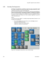
The Keyer menu controls are organized into several subcategories, each with different
menu selection based on the type of key. These menus are accessed by touching the
Keyer button in the Home menu. Keyer selections like key type, Key Invert, Matte
Fill, can be made for any keyer from the Main panel using the Keyers subpanel. These
controls are on the Main panel for immediate access.
However, key adjustment for detail, such as clip and gain, and mask controls, are
accessible from the corresponding Keyer menu. The Keyer subpanels and the
corresponding menus will reflect and track the changes made by either set of controls.
The Keyer menu controls are organized into several subcategories, each with different
menu selection based on the type of key. These menus are accessed by selecting the
appropriate keyer via the Delegation popup button, then the category is chosen from
the Mode, Priority or Mask and Mattes buttons at the bottom of the menu.
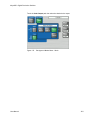
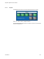
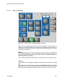
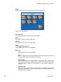
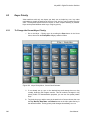
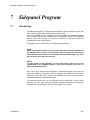
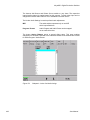
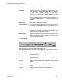
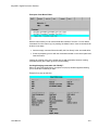
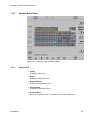
Figure 120
Keyer Menu
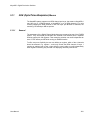
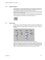
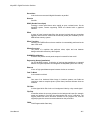
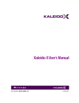
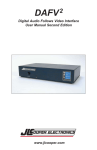
The Keyer menus allow to control the key generators for each of the full-function M/Es.
The Keyer menus, like the Wipe menus, have a delegation area at upper left , which in
this case contains the key generator selector.
192
User Manual
KayakDD - Digital Production Switcher
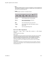
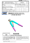
5.6.1
Key Mode
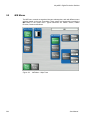
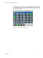
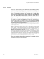
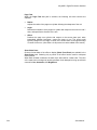
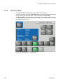
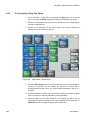
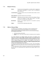
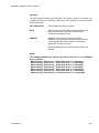
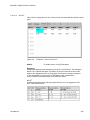
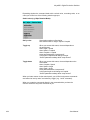
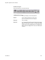
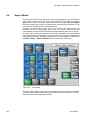
Figure 121
Keyer Menu – Mode Selection
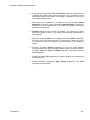
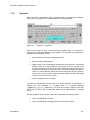
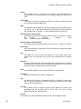
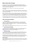
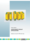
The Mode menu allows you to select the type of key for any of the four keyers in each
M/E or P/P. Touching the Mode subcategory button brings up the Keyer Mode menu.
Touch the keyer data pad you wish to select, then select the Mode from one the
selections described below. Key modes are selectable from the following choices:
•
•
•
•
•
Luminance
Luminance Linear
Additive Key
Chroma Key
Preset Pattern
Luminance Key is used for key sources with an unshaped fill signal
Linear Key is just a shortcut for a special setting of the Luminance Key:
Gain 100% and Clip 50%
Additive Key is used for key sources with a shaped fill signal
For a complete overview on key types and adjustments, refer to section Keying on
page 34.
User Manual
193
KayakDD - Digital Production Switcher
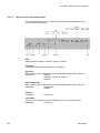
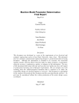
5.6.2
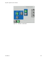
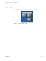
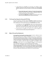
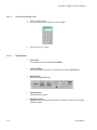
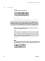
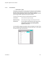
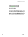
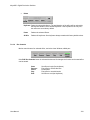
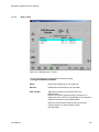
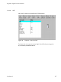
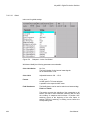
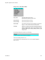
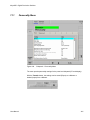
Keyer Priority Misc Menu
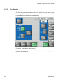
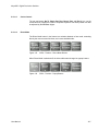
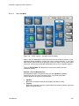
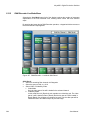
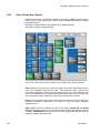
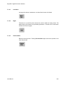
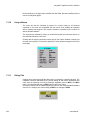
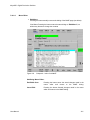
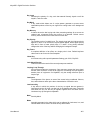
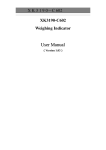
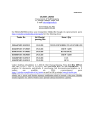
Touching the Priority Misc subcategory button takes you to the Priority menu (Figure
below). The Priority menu is used to change the stacking order of the keys.
The parameter control area on the right has two columns, labeled Current and Next.
The stacking order of the selected item in a column is controlled with the Top, Move
Up, Move Down, and Bottom touch buttons. Changing the top to bottom order in the
Current column will cause an immediate change in that keyers stacking order. The
order in the Next column controls the order the keys will have after the next key priority
transition. After the key priority transition, the Current and Next stacks will swap.
The Key Prior and Key Over buttons in the Keyer subpanel on the panel provide an
alternate method for setting key priority. Refer to Key Prior Button and Key Over
button.
Figure 122 Keyer Menu - Priority
194
User Manual
KayakDD - Digital Production Switcher
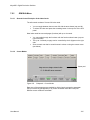
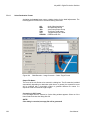
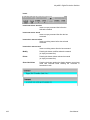
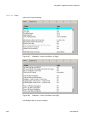
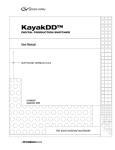
5.6.3
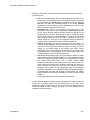
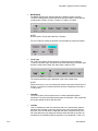
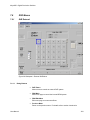
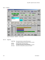
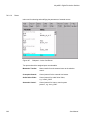
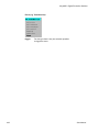
Keyer Mask Menu
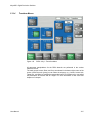
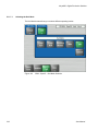
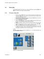
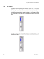
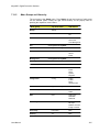
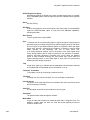
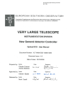
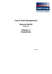
Touching the Mask subcategory button takes you to the Keyer Mask Point of Use menu
(Figure below). The Mask menu allows selection and control of the keyer mask(s). Key
masking defines areas that are protected from keying (Inhibit) or always key (Force).
The shape of the mask can originate from a wipe pattern generator or by a selected
mask signal (typically a key fill signal delivered via the Utility bus).
The keyer delegation (Key1 – Key4) is made at the top left of the screen. Once a keyer
has been delegated, choose the type of mask (Force or Inhibit, or both) from the data
pad in the lower right corner. The example shown here is for a Wipe Force Mask on
Key 1.
Figure 123 Keyer Menu – Mask
User Manual
195
KayakDD - Digital Production Switcher
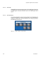
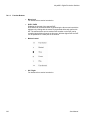
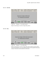
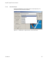
5.6.3.1
Mask Sources
For either type of selected mask (Force or Inhibit) five different mask sources are
available and will appear as popup selection when you press the Mask Source button.
Only one mask source can be selected at a time.
Figure 124 Keyer Menu – Mask Source
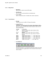
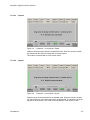
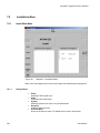
5.6.3.1.1
Box
When Box is selected as the mask source, you can adjust softness and opacity. The
four edges of the box can be set separately.
Figure 125 Keyer Menu – Box Mask
196
User Manual
KayakDD - Digital Production Switcher
5.6.3.1.2
Keyer Wipe
A Keyer Wipe mask source allows selection of a wipe pattern from the dedicated
pattern generator for the keyer. Touch the Patt. Sel/Adj button in the menu to bring up
the wipe pattern selections available (Figure below). Select a pattern from the display.
The selected pattern will appear in the Patt. Sel/Adj data pad window. Select the other
datapads in the wipe menu to adjust pattern modifiers. These include pattern
positioner, rotate, H and V multiply, and aspect controls, similar to the wipe controls.
Modifiers are controlled by the soft knobs on the right of the screen.
Figure 126 Keyer Menu - Wipe Mask
5.6.3.1.3
Complex Wipe 1 and 2
A mask can be generated from a complex wipe source. There are two complex wipe
generators available, Complex Wipe 1 and 2. The pattern for the complex wipe is
chosen in the same manner as the keyer wipe mask. The complex mask wipe can also
be modified for position, rotation, H and V multiplication and aspect. In addition, wipes
can be mixed and modulated.
Keyer and complex wipe masks must share the wipe generators with other functions
with wipe capability in the switcher. This resource sharing must be considered when
delegating one of the wipe generators to a mask.
CAUTION!
All controls in the Wipe1 Generator or the Wipe2 Generator affect the selected wipe
pattern generator.
User Manual
197
KayakDD - Digital Production Switcher
5.6.3.1.4
Utility Bus
The Utility Bus mask sources originate from the utility bus in the chosen M/E.
Typically these are used to bring in garbage masks from a Still Store or some external
device.
Figure 127 Keyer Menu – Utility Bus Mask
5.6.3.1.5
Mask On Button
The Mask may be turned on or off by selecting the Mask On button.
5.6.3.1.6
Mask Invert Button
The Mask Invert button inverts the sense of the delegated mask. When off, areas
formerly masked will be visible, and previously visible areas will be masked. Masks are
normally active in the center of the pattern. An inverted mask is active outside the
pattern.
198
User Manual
KayakDD - Digital Production Switcher
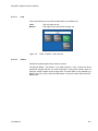
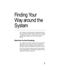
5.6.4
Keyer Mattes Menu
The Matte menus give you control over matte color, type, and appearance. There are
no local matte controls on the Main panel; all matte adjustments are made in the
menus. The Popup delegation button in the top left of the menu allows you to select
the mattes of the different keyers. Soft knobs are provided on the right side of the
menu for adjustment of matte parameters.
Figure 128
User Manual
Keyers Mattes Menu
199
KayakDD - Digital Production Switcher
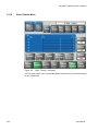
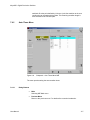
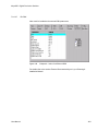
5.6.5
Chroma Key
When a chroma key is selected, the menu (Figure 129) will display a summary of all
chroma key parameter values at the same time. The parameter groups should be
adjusted in the following order:
1.
2.
3.
4.
Prim Suppress
Key Control
Sec Suppress
Other
After the first two parameter groups have been adjusted, a reasonable key should be
visible. Subsequent adjustment steps may improve the basic key in subtle ways.
See section Chroma Key Operating Notes on page 283 for more information on setting
up a chroma key. For a concept overview of chroma keying, refer to section Chroma
Key on page 43.
Figure 129
200
Keyers Mode Chroma Key Menu
User Manual
KayakDD - Digital Production Switcher
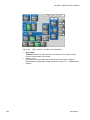
5.6.6
Preset Pattern
A preset pattern uses a wipe pattern generator, rather than an incoming key cut signal
to define the hole cut in the background. When Preset Pattern is chosen as the keyer
mode, the menu will appear as in Figure below. When the Pattern data pad is
touched, the Wipe menu (see Wipe Menus) will come up to allow pattern selection.
The Preset Pattern may be matte-filled by touching the Matte Fill data pad.
The matte controls can be accessed by touching the Mattes button. Opacity and size
of the preset pattern can also be adjusted with the soft knob controls on the right of the
screen.
Figure 130 Keyer Mode – Preset Pattern
User Manual
201
KayakDD - Digital Production Switcher
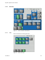
5.7
Background Mattes Menus
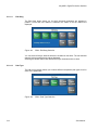
When Bgnd Mattes is selected, the menu displays two panes for control of Color BGD 1,
Color BGD 2 and Color BGD 3, including base and wash colors, wash direction and
offset, and wash edge texture attributes. Each touch pad activates the soft knobs to
control those parameters.
Figure 131
202
Background Matte Menu
User Manual
KayakDD - Digital Production Switcher
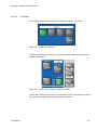
Touch the Color Output pad, then select the desired color output:
Figure 132
User Manual
Background Mattes Menu - Wash
203
KayakDD - Digital Production Switcher
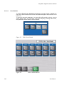
5.8
M/E Menus
The M/E menu controls are organized into two subcategories, each with different menu
selection based on the type of transition. These menus are accessed by touching the
M/E button in the Home menu. Typical selections are Pattern Source, Pattern
Direction, Border and Softness.
Figure 133
204
M/E Menu – Wipe Trans
User Manual
KayakDD - Digital Production Switcher
Figure 134
User Manual
M/E Menu – Border Matte
205
KayakDD - Digital Production Switcher
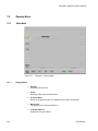
5.9
YUV Bus Correction Menus
The YUV Correction menu serves to adjust brightness, contrast, saturation and
color balance related to the bus.
Figure 135
YUV Bus Correction Menu
The correction can be made in the following buses:
•
•
•
Bus (PGM, PST, Key1 ... Key4)
NOTE!
If Bus Correction for PGM bus and/or PST bus is selected, the two settings
are exchanged at the end of a fading.
Input (all input signals)
Aux (all Aux buses)
NOTE! Bus correction has priority over input correction.
Reset Bus
Reset the values for a single bus of the selected M/E to their default value.
Reset M/E
Reset the values for all busses of the selected ME to their default values.
Color Off
Switched the color on/off completely separate for each bus.
206
User Manual
KayakDD - Digital Production Switcher
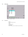
5.10
RGB Input Correction Menus
RGB Input Color Correction is a software enabled feature that converts the video
signal on a particular video bus from color difference format to RGB (red, green, blue)
color component format, applies separate offset, gain, and gamma to each RGB
component, then converts from RGB back to color difference (Y, Cb, Cr) format. The
color correction is applied on an input by input basis. The parameters are applied on
the basis of a source and bus intersection and stored as part of source memory. A
different input on the same bus or a same input on a different bus, may have different
color correction.
The Color Corrector menu is used to adjust RGB color on a selected bus and input.
Corrected inputs and parameter will be displayed in a yellow style.
Figure 136
RGB Input Correction Menu
The Adjustment Mode pad has two buttons, the first two, Gain/Lift and White/ Black,
determine the mode for the knobs and the text boxes in the Color Corrector Transfer
Function pane “Red/Green/Blue”.
Gain/Lift
White/ Black
User Manual
Adjust a offset to Black level
Adjust Black and White in percent
207
KayakDD - Digital Production Switcher
When the Reset button is touched, the following modes can be selected:
•
•
•
Reset Color
Reset Input
Reset all Inputs
When one of the Red, Green, or Blue color component's button is selected, the knobs for
Gain, Lift, and Gamma are delegated for the specific component. For example, if Green
had been selected, the knobs would control the green channel's values, and similarly
for Red and Blue.
The Changes on red also apply to pane has two on/off buttons. The title and the button
labels are dependent on the selection of the color component in the Color Corrector
Transfer Function pane “Red/Green/Blue”. If the user selects Blue as the color to be
adjusted, the two buttons are Red and Green. When these buttons are active, the
adjustments applied to the originally selected color component is also applied to the
one(s) selected in the pane. For example, if the user chooses to adjust Blue and
selects Red in the “Changes on Blue also apply to” pane, then any adjustments to
Blue's Gamma value will be applied to Red's Gamma value.
Note that changing from Blue to either Green or Red in the Color Corrector Transfer
Function panel will cancel the attachment.
208
User Manual
KayakDD - Digital Production Switcher
5.11
DPM (Digital Picture Manipulators) Menus
The KayakDD system supports one DPM channel per keyer, that means a KayakDD-1
may have up to 4 DPM channels, a KayakDD-2 up to 8 DPM channels. For units
currently shipping the DPM channel for the first keyer per ME-bank is standard, the
remaining 3 channels per ME are options.
5.11.1
General
The parameters of the Digital Picture Manipulators are not stored as part of the E-MEM
system. They are treated per ME-bank like external DVE channels with a separate
timeline system with 100 registers. That means the switcher can recall independent an
extra “t” DVE effects per ME while running an E-MEM timeline.
To offer even more flexibility the user can define per register, which of the 4 channels
should be affected. E.g. register 1 could only include the DPM channel of keyer 1
running an endless loop to spin a logo while the user is able to recall independently
other registers containing only channel 3+4 displaying differently sized boxes.
User Manual
209
KayakDD - Digital Production Switcher
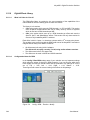
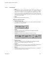
5.11.2
Misc. Setup Menu
Figure 137
DPM – Misc - Setup Menu
This menu is the start menu for building an effect. In the top row you select which
channels should be part of the effect. Channels that are not included will not be stored
and will not be affected when the register is recalled. In the second row you can switch
on global control per included channel. If global control is switched off for a global
channel, that channel will not be affected by global channel parameters; e.g. by a
global rotation.
AutoRun button
When AutoRun is on a recall of an DPM effect will automatically run the effect. When
AutoRun is off, the run has to be triggered either in the Show Timeline menu by
pressing "Play" or by pressing the cut button in the Effects area again while the section
is delegated to DPM control.
The AutoRun button is also used when a DPM effect is recalled by an E-MEM.
When “on”, a keyframe containing DPM Eff. No in the Define Memo will trigger an
immediate run of the relevant DPM effect. (Define memo is set in the E-MEM define
memo menu.)
When “off”, a trigger has to be set to run the effect (in current software this is only
possible via the Sidepanel program.
210
User Manual
KayakDD - Digital Production Switcher
In the Key – Priority – Misc menu you can switch on DPM effect loop for the chosen
keyers (Loop On) and select the flipside of an effect (Use Src). This information is not
part of a DPM effect and should be set manually or recalled by an E-MEM recall (like
the keyer parameter settings).
Figure 138
User Manual
Key Selection for DPM Channels
211
KayakDD - Digital Production Switcher
5.11.3
Drop Shadow
The Drop Shadow feature is turned on with the Drop Shadow button. When turned on,
soft knob controls become available on the right. Different soft knob controls appear,
depending on which data pad has been selected in that pane. The current parameter
names and values are displayed on each data pad.
Figure 139
DPM – Misc – Drop Shadow 1
When Shadow is selected soft knobs for X Offset, Y Offset, Size, and Opacity are
available. See figure above.
212
User Manual
KayakDD - Digital Production Switcher
When Shadow Color is selected soft knobs for Hue, Saturation, and Brightness
are available.
Figure 140
DPM – Misc – Drop Shadow 2
Drop Shadow Controls
The DPM button near the 3D positioner delegates it to drop shadow control. The 3D
positioner X and Y axis adjust the drop shadow offset from the primary image and the
Z axis controls the size of the drop shadow.
User Manual
213
KayakDD - Digital Production Switcher
5.11.3.1
Shadow Crop
The Shadow Crop controls are used to adjust shadow cropping and edge softness.
The current parameter names and values are displayed on the data pads.
Figure 141
DPM – Misc – Shadow Crop
When Use Image Crop is selected, crop values of the shadow match the crop values
used for the primary image. Only shadow edge softness controls are active in this
mode.
When the Crop Softness data pad is selected soft knob controls for shadow edge
softness are available (Top, Bottom, Left, and Right). The total softness of the drop
shadow edges will be the softness of the shadow edge combined with any softness of
the primary image.
When Use Shadow Crop is selected, the edges of the drop shadow can be given crop
values different from the primary image.
214
User Manual
KayakDD - Digital Production Switcher
5.11.4
Transform Menus
Figure 142
DPM – Key 1 -Transform Menu
All parameter manipulations for the DPM channels are performed in the various
transform menus.
The main groups Locate, Skew, and Crop are selected in the bottom right corner of the
screen. Inside the main group you can select the subgroup, e.g. Locate, Locate Axis,
Target Rot., and Spin by pressing the appropriate button. Per Subgroup you can adjust
the parameters for Source and for Target. For more information on this issue see
chapter on Concepts.
User Manual
215
KayakDD - Digital Production Switcher
5.11.4.1
Edit Gang
The Edit Gang button shows you for which channels parameters are adjusted in
parallel. If more than one channel is selected, the values of the top channel are
displayed.
Figure 143
DPM – Edit Gang Selection
You can select all Keyer channels which are included in this effect. The last selected
channel is the one which has its values displayed.
Selecting the Global channel will deselect the Keyer channels and vice versa.
5.11.4.2
Path Type
The path control section allows you to select different interpolation path types for all or
some of the parameters.
Figure 144
216
DPM – Path Type Selection
User Manual
KayakDD - Digital Production Switcher
5.11.4.3
X, Y, Z Spin
For the subgroup Spin the path type can be different for the X,Y, and Z spin.
Figure 145
DPM – Spin Selection
To adjust the parameters for Tension, Continuity, and Bias press the relevant button in
the path control section.
Figure 146
DPM – Adjust Tension, Continuity, and Bias
If Path Hold is selected, there will be no interpolation between the keyframes and the
new value will be applied when the next keyframe is reached.
User Manual
217
KayakDD - Digital Production Switcher
5.11.4.4
Crop
Figure 147
DPM – Key 1 – Transform - Crop
The menu serves to trim the image. In addition the softness of the edges can be
adjusted and the image can be mirrored horizontal and vertical with Reverse Front
and Reverse Back. The Easy Cube button forces channels built into a 6 sided solid to
stay visible only when such an object would display them and also moves the channels
automatically to their opposite side as the solid rotates. It does not build a cube
automatically.
218
User Manual
KayakDD - Digital Production Switcher
5.11.5
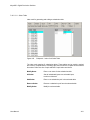
Timeline Menus
The timeline menus consist of two main groups, Save/Recall and Edit.
5.11.5.1
Save/Recall Menu
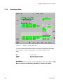
Figure 148
DPM – Timeline – Save/Recall Menu
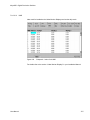
This menu gives you an overview of all 100 registers. You can select any register for
recall, edit or modify. The green line indicates the current effect, the blue line is the
cursor.
User Manual
219
KayakDD - Digital Production Switcher
5.11.5.2
Save / Discard
This button is only enabled when you have modified the current effect in the Timeline/
Edit menu. Once you have made changes the pop-up menu shown below allows you
to either save the changes permanently or discard them. If the Effects section is in
control of DPM the question is also asked in the display there. It is answered by
pressing "Enter" to save changes and by "Clear" to discard them.
Figure 149
DPM – Timeline – Save/Discard
Since the Timeline/Edit menu always refers to the current effect, there are two ways to
start an effect for an empty register:
• Recall an empty register in the menu to select it as the current effect and add
keyframes via Insert in the timeline / edit menu.
• Use the Store button in the main control panel to select an empty register by using
the Store Free” dialogue as the current effect and add the first keyframe.
5.11.5.3
Recall
Select a register and press Recall.
This button is disabled when the current effect is modified and the modification is not
yet saved or discarded.
220
User Manual
KayakDD - Digital Production Switcher
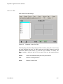
5.11.5.4
Modify
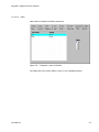
The modify button allows you to rename or to delete the selected register.
Figure 150
User Manual
DPM – Timeline – Modify
221
KayakDD - Digital Production Switcher
5.11.5.5
Use Priority
If the Use Prio. button is activated, the key priority of the included keyers will be set by
the DPM effect on a keyframe by keyframe base. If such a DPM register is recalled by
an E-MEM register, any priority information stored in the E-MEM register will be
ignored.
5.11.5.6
Use Video Sources
If this function is activated for a keyer, the source selection for the selected keyer will
be set by the DPM effect on a keyframe by keyframe base. If such a DPM-register is
recalled by an E-MEM-register, the source information for the relevant keyer stored in
the E-MEM-register will be ignored.
Figure 151
222
DPM – Timeline – Video Sources
User Manual
KayakDD - Digital Production Switcher
5.11.5.7
Loop
This function allows you to put the selected effect in an endless loop:
Loop:
Bounce:
Figure 152
5.11.5.8
Run from begin to end.
Run begin to end, then reverse to begin, etc.
DPM – Timeline – Video Sources
Protect
Protects the register against save, delete or rename.
The buttons Modify / Use Priority / Use Video Sources / Loop / Protect are direct
permanent changes that do not need confirmation. Using these function does not
select the chosen register as the current effect. A current effect is only selected by a
Recall in the menu, by the Store and Edit button on the main control panel and by EMEM recalls.
User Manual
223
KayakDD - Digital Production Switcher
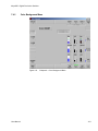
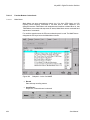
5.11.6
Show Timeline Menu
Figure 153
DPM – Timeline – Edit Menu
The Edit menu allows you to insert/modify/delete keyframes for the selected channels
for the current effect.
224
User Manual
KayakDD - Digital Production Switcher
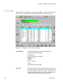
5.11.6.1
Delegation
The Delegation button shows you for which channels the actions are executed.
Figure 154
DPM – Timeline – Delegation Selection
You can select all Keyer channels which are included in this effect. The last selected
channel is the displayed one.
User Manual
225
KayakDD - Digital Production Switcher
5.11.6.2
Sure Touch
“Sure Touch” changes the way in which effects behave during recall and playback,
providing more control and flexibility. An effect can be safely recalled using two new
modes which eliminate abrupt changes: hence the name “sure touch” is being used.
When using a Sure Touch mode, the effect adapts itself to the switcher’s current state.
Upon recall of any effect, no changes are made to the current state, regardless of the
nature or the composition of the effect. Then, when the effect is run, the relative
changes from the interpolated effect are applied instead of the traditional absolute
output. Only elements which changed over the course of the original effect are
affected.
One way of thinking about safe touch is to think of it as running an effect in “relative”
mode.
These changes can be applied in different ways, allowing the effect to interpolate on a
path parallel to the original effect (Parallel mode), or on a path that converges the
changing state smoothly to the actual end state of the original effect (Converge
mode). A safe touch mode can be “forced on” just prior to recalling an effect, or it can
be saved with the effect to be used automatically.
This feature changes the paradigm of control for effects, allowing effects to be applied
under more flexible set of conditions and also to be used as specialized functions to
perform specific actions.
Within the DPM timeline system, when an effect is first created, a snapshot of all
values is saved. For any subsequent keyframes, only values which have changed are
then saved. Those values that have changed are referred to as “bound elements” and
are subject to interpolation as the effect runs.
When an effect is recalled in a sure touch mode, the current states of the bound
elements are read by the timeline system. These values are compared with the original
first keyframe (snapshot) of the effect, and an “offset” or “new zero” is established for
each bound element of the effect. This “offset” is then applied during all subsequent
fields of the effect. A new “offset” is established each time the effect is recalled. The
result is that a “new effect” is established each time the effect is recalled.
The essential result is this: When an effect is recalled in a safe touch mode, only those
values which underwent changes after the first key-frame of the original effect are
touched, and only changes in values are applied.
226
User Manual
KayakDD - Digital Production Switcher
5.11.6.3
Cursor Control
The top row buttons Go To, Begin, Rev Play, Pause, Play, and End let you run the
current effect or position the cursor to a specific keyframe. The effect position can also
be adjusted by the Eff. Pos. digipot.
5.11.6.4
Direct Mode
The Direct Mode button in the bottom row switches between a fast mode, accessing
directly the most common functions, and a more detailed mode.
Figure 155
DPM – Timeline – Direct Mode Buttons
When Direct Mode is switched off, the direct edit buttons change into popup buttons:
Figure 156
User Manual
DPM – Timeline – Popup Buttons
227
KayakDD - Digital Production Switcher
5.11.6.5
Modify Keyframe
Figure 157
DPM – Timeline – Modify Keyframe
NOTE!
When the cursor is at a keyframe, the parameters of this keyframe will be modified to
the current values, When the cursor is between keyframes, modify inserts a keyframe
at the current position without adding any time. Modify All applies current keyframe
changes to all keyframes.
5.11.6.6
Insert
Figure 158
DPM – Timeline – Insert Buttons
NOTE!
When the cursor is at a keyframe, a new keyframe will be inserted, adding the time
which is specified with Keyframe Duration, When the cursor is between keyframes, the
keyframe is inserted at the current position without adding any time.
228
User Manual
KayakDD - Digital Production Switcher
5.11.6.7
Delete Keyframe
Figure 159
DPM – Timeline – Delete Buttons
NOTE!
When deleting a keyframe its duration is also deleted causing effect duration to
change.
5.11.6.8
Keyframe Duration
Figure 160
DPM – Timeline – Duration / Start Time Buttons
NOTE!
The Keyframe Duration button is NOT used to change the keyframe duration of the
current keyframe. The time is used for the insert of a new keyframe when inserted
while the cursor is on a keyframe (see Insert Keyframe).
User Manual
229
KayakDD - Digital Production Switcher
5.11.6.9
Constant Duration
The function of this button is the same in both modes. If selected, inserting or deleting
will not change the total duration of the effect. Inserting a keyframe while the cursor is
at a keyframe position, the new keyframe will add the time specified by Keyframe
Duration, but the total effect duration will be rescaled to keep it at the previous
duration. When a keyframe is deleted, its keyframe duration will be added to the
previous keyframe.
230
User Manual
KayakDD - Digital Production Switcher
5.11.7
SpecFX Kurl Menu
The Kurl effects are grouped into modes, each of which has its own set of
menu panes and related soft knob controls.
The Kurl modes are:
•
•
•
•
Page Turn
Page Roll.
Position/Size Modulation,
Slits
A Digital Picture Manipulator can apply only one set of Kurl mode parameters at a
time. If you wish to use more than one mode of Kurl effects simultaneously on the
same video (for example, size modulation of an effect), use multiple Digital Picture
Manipulators with re-entry.
Figure 161
User Manual
DPM – SpecFx – Kurl Menu (Off)
231
KayakDD - Digital Production Switcher
5.11.7.1
Selecting the Kurl Mode
The Kurl Mode button allows you to select different operating modes.
Figure 162
232
DPM – SpecFx – Kurl Mode Selection
User Manual
KayakDD - Digital Production Switcher
5.11.7.2
Page Turn / Roll Mode
Figure 163
DPM – SpecFx – Kurl Menu (Page Turn Mode)
Page Turn is a transition effect with the video being mapped to an original plane, a
cylinder, and a final plane parallel to the original plane. Page Roll maps the video to an
original plane and a cylinder. Page Turn and Roll are parallel projections to the target
screen with no perspective.
NOTE!
For a Page Turn effect on a key or video that is not a full raster, you will need to
set up two identical keys and use the Show Sides Front and Back buttons to
define the position of each key.
Touch the Page Turn/Roll Kurl Mode button to access the Page Turn and Roll controls
Fold Pane:
The orientation of the fold (Over or Under the original plane) are selected in the Fold
pane.
Split page turn and roll effects are controlled with the Split Axis buttons. The effect
can be split Horiz, or Vert, or both ways using the labeled buttons. Selecting the Split
Axis buttons brings up Horiz and Vert soft knobs that control the location of the split.
User Manual
233
KayakDD - Digital Production Switcher
Page Fold:
When the Page Fold data pad is selected, the following soft knob controls are
available:
•
Radius
Adjusts the radius of the page turn cylinder affecting the sharpness of the curl.
•
Angle
Defines the orientation of the page turn cylinder with respect to the source X and Y
axes, and specifies the direction of the turn.
•
Offset
Positions the page turn cylinder with respect to the source plane and, when
interpolated between keyframes, causes the page to turn. The offset would
typically change from one edge or corner of the source raster to the opposite edge
or corner for the turn. (Hint: Offset = 0 will put the turn at the middle of the screen.)
Show Sides Pane:
Choices of what sides of the effect to display (Both, Front, Back) are available in the
Show Sides pane. Selecting only a portion of the effect can be used for multi-pass
effect creation.
When Back is Matte is selected, the back of the effect will be a matte color. The color
of the matte can be changed by touching the Back Color data pad to bring up soft knob
controls for Hue, Saturation, and Brightness.
234
User Manual
KayakDD - Digital Production Switcher
5.11.7.3
Pos / Size Mode
Figure 164
DPM – SpecFx – Kurl Menu (Pos/Size Mode)
Position and Size Modulation are effects in which the source video is position- or sizemodulated through an additive process with either a single wave train, or two wave
trains with the second wave at a right angle to the first. Each of the two wave trains
(horizontal, vertical) may be selected independently from a set of modulation patterns.
Touch the Pos/Size Modul. Kurl Mode button to access the position and size
modulation controls.
Horizontal or Vertical (Modulation) Pane:
In the Modulation pane you select the wave train axis (Horizontal or Vertical)
for which the rest of the menu controls will apply. The following Soft knob
controls appear on the right for the selected axis:
•
•
User Manual
Amplitude
Defines the modulation amplitude (the height of the pattern waves).
Frequency
Defines the modulation frequency and therefore the number of pattern cycles that
appear across the source.
235
KayakDD - Digital Production Switcher
•
Phase
When Phase Lock is on, the Phase soft knob is available to control the static
location of the phase of the pattern.
When Phase Lock is off, the Speed soft knob is available to adjust the speed of the
pattern’s motion. Negative values can be entered to reverse the direction of the
motion.
When data pad CenterX, CenterY, Axis is selected soft knob controls for CenterX,
CenterY and Angle are available to define the angle and position.
Horiz. or Vertical Mode Pane:
With an axis selected, you select the type of modulation to be applied to that axis (Off,
Pos, Size or Cancel) in the Mode Type pane.
Figure 165
DPM – SpecFx – Kurl Menu (Horiz. Mode Selection)
When the Vertical axis is selected, you can choose to have that axis’ modulation values
match the horizontal values with the V Mode follow H button.
When Size is selected in the Mod Type pane, the CenterX/Y/Angle data pad in the is
active. When this data pad is selected soft knob controls for CenterX, CenterY, and
Angle are available
236
User Manual
KayakDD - Digital Production Switcher
Pattern Pane:
The type of wave pattern to be applied to the selected axis and modulation type is
selected in the Pattern pane.
User Manual
Figure 166
DPM – SpecFx – Kurl Menu (Pattern Selection)
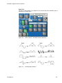
Figure 167
Available Wave Patterns
237
KayakDD - Digital Production Switcher
Figure 168
•
•
238
DPM – SpecFx – Kurl Menu (Pos/Size Mode)
Cycle Limiting
The Button activates the Cycles soft knob. This control can be used to limit the
number of wave pattern cycles visible.
Pattern + Only
The Button acts like a rectifier and converts all wave excursions to positive.
Representative resulting wave shapes are shown in Figure 167 Available Wave
Patterns.
User Manual
KayakDD - Digital Production Switcher
5.11.7.4
Slits Mode
Slits is an effect in which the source video is split into a number of parallel slits. The
width of the slits may be uniform or random, and an angle may be specified. An offset
function is provided which controls the amount of displacement of alternating slits in
opposite directions (to cause a transition type effect).
Touch the Slits Kurl Mode button to access the slits controls. When the Modulation
data pad is selected the following menu appears.
Figure 169
DPM – SpecFx – Kurl Menu (Slits Mode)
The Slit modulation soft knob controls and wave patterns are the same as
Position/Size mode specified in section 5.11.7.3
User Manual
239
KayakDD - Digital Production Switcher
When the Slits data pad is selected a menu similar to Figure 180 appears.
Figure 170
DPM – SpecFx – Kurl Menu (Slits Mode)
Soft knob controls are provided to control the following attributes of the
slits:
•
Offset
Sets the distance adjoining slits move away from each other. This can be used for
transition effects, using a zero offset for the first keyframe and an off-the-screen
offset for the last keyframe.
•
# Slits
Defines the number of slits.
•
Phase
Determines the starting point or phase of the modulation for the center point.
•
Random
Defines the degree of randomization of slit width.
•
Angle
Defines the angle of the slits with respect to the source X and Y axes.
240
User Manual
KayakDD - Digital Production Switcher
5.11.8
Misc Menu
Figure 171
5.11.8.1
DPM – Kurl Mode – Misc Selection
Setup
Select the included keyer and allow global control.
Figure 172
User Manual
DPM – Misc Setup
241
KayakDD - Digital Production Switcher
5.11.8.2
Set to Defaults
To reset all Digital Picture Manipulator parameters or groups of them to default you
can use the Set to Defaults menu which is accessible through the Misc selection in the
button row.
To reset only geometric parameters, i.e. those which affect position, size etc., use the
"Geom Parms" reset. The "All Parms" reset sets everything, including matte colors,
drops shadows, mirrors and Kurl values to default.
Figure 173
Figure 174
242
DPM – Set to Default
DPM – Default Selection
User Manual
KayakDD - Digital Production Switcher
5.11.8.3
Drop Shadow
The Drop Shadow feature is turned on with the Drop Shadow button. When turned on,
soft knob controls become available on the right. Different soft knob controls appear,
depending on which data pad has been selected in that pane. The current parameter
names and values are displayed on each data pad.
For more details refer to section 5.11.3.
5.11.8.4
Priority
Figure 175
User Manual
DPM – Timeline – Modify
243
KayakDD - Digital Production Switcher
5.11.9
Digital Effects Library
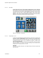
5.11.9.1
What is it? How do I Use it?
This DPM effect library is provided to give users examples of the capabilities of the
internal DPM as well as a starting point to create own effects.
The library is in 2 sections:
•
C1fx is the section which uses only DPM channel 1 on P-P and ME1. This section
uses 3D-planar transformations and can be easily used by owners of systems
which do not have 4 DPM channels per M/E.
•
C4fx is the section which uses up to 4 DPM channels per effect and uses the
SpecFX: Kurl™ and Splits/Mirrors effects. This section will only show results for
owners of fully loaded KayakDD™ switchers.
Each effect is built in 2 parts: 1 to introduce a picture and the 2nd to remove the picture.
This enables users to work live with the DPM recall area of the KayakDD™ and also to
integrate effects easily into E-MEM™ timelines.
•
•
•
5.11.9.2
All effects were built using V664.2 software.
The effects will not replay correctly, if at all, using earlier software versions.
The effects were built for 4:3 aspect ratio.
The effects can be used in 625/50 and 525/60 standard.
Configuration Notes for DPM
In the Config / Ebox-DPM settings area of your switcher are very important settings
which affect the edges of pictures in DPM channels. If you use sources which have
been digitally sourced you should ensure that the production crop settings for 4:3 are
set to Top = 3.05, Left = -4.16, Right = 4.16, Bottom = -3.05.
These figures will ensure the correct viewing of the effects in this package.
Figure 176
244
Config - DPM – Timeline – Modify
User Manual
KayakDD - Digital Production Switcher
5.11.9.3
How to Load the Effects to Your Switcher
Use the memory stick for your system to make a copy of your working application.
•
•
•
•
•
Insert your stick in USB slot 2 or 4.
Go to the CONFIG menu. It will open in Application Control window
Press SAVE – your application will be saved to the stick
Press SAVE AS and give your application a new name, this could include the
letters FX.
You now have 2 copies of your working application. The first is a working backup,
the second will become your copy with an effects library
Use your PC to add the effects library to your 2nd application copy.
•
•
Connect your USB memory stick to your PC
Using windows explorer to navigate to the folder on your computer that contains
the effects libraries. There are 2 folders; 1 is called C1fx, the other is called C4fx.
In these are folders named te_eff0 and te_eff1. Highlight 1 of these folders and
press the “copy to” button in the windows tool bar.
“Copy to” button
•
User Manual
In the window that opens navigate to your memory stick and open the “appli”
folder. In this navigate to the folder named as you named your copy of the active
application on your KayakDD™ and then to the MF1 folder.
245
KayakDD - Digital Production Switcher
With this folder highlighted press OK. Windows will ask you to confirm that the
existing te_eff0 or te_eff1 folder may be overwritten as all data within it will be
replaced with the library effects. If you are happy that you have highlighted the
correct application answer “yes”.
You do not have to copy both te_eff0 and te_eff1 to a 2 M/E KayakDD™ unless you
want both mix effect banks to have access to the effect library.
You do not have to copy the same library (C1fx or C4fx), so you could use C1fx from
te_eff0 and C4fx from te_eff1.
If you have a KayakDD™ 1 M/E unit the te_eff1 folder exists, but this is a folder made
for compatibility only. If you save effects to this folder it will be emptied when the
KayakDD™ saves the application.
In the package of software you will find a folder named “ramrecStills”. This folder
contains 4 files which are full frame graphics that you can use to name the 4 keyers on
an M/E using RamRecorder. You will have to use a PC running the sidepanel program
to transfer these pictures to your KayakDD™ and full instructions on how to use the
ram recorder transfer system are in this KayakDD™ user manual.
To replay and use an effect refer to the section Catalogue of Effects below.
246
User Manual
KayakDD - Digital Production Switcher
5.11.10
Catalog of Effects
5.11.10.1
C1fx – for Channel 1 Only.
Naming:
sl = slide
ps = perspective slide
lb = linear motion bounce
spir = spiral
bnc = multi position bounce
sw = swoop
bri = barrel roll in
bro = barrel roll out
Positions in or out of frame:
T = Top Centre
B = Bottom Centre
L = Left Centre
R = Right Centre
TL = Top Left corner
TR = Top Right corner
BL = Bottom Left corner
BR = Bottom Right corner
C = Fully centred
Channel names:
C1, C2, C3, C4 = Channel numbers.
All effects in the C1fx section may be used with either full frame pictures or keyed
elements.
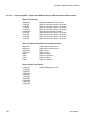
Bank 00: Slide and zoom with shadows. Effects are 1:00 seconds in duration.
Zoom OUT
C1sl-LC
C1sl-RC
C1sl-TC
C1sl-BC
C1sl-CL
C1sl-CR
C1sl-CT
C1sl-CB
User Manual
247
KayakDD - Digital Production Switcher
Bank 01: Corner slides and spin zooms with shadows. Effects are 1.00
SpinZoom Out
C1sl-TLC
C1sl-TRC
C1sl-BLC
C1sl-BRC
SpinZoom IN
C1sl-CTL
C1sl-CTR
C1sl-CBL
C1sl-CBR
Bank 02: Perspective slides and spiral zooms
C1spir-OUT
C1ps-LC
C1ps-RC
C1ps-TC
C1ps-BC
C1spir-IN
C1ps-CL
C1ps-CR
C1ps-CT
C1ps-CB
Bank 03: Linear Bounce
C1bncOUT
C1lb-LC
C1lb-RC
C1lb-TC
C1lb-BC
C1bncIN
C1lb-CL
C1lb-CR
C1lb-CT
C1lb-CB
Bank 04: Swoop IN/OUT
C1sw-OUT
C1sw-TLC
C1sw-TRC
C1sw-BLC
C1sw-BRC
C1sw-IN
C1sw-CTL
C1sw-CTR
C1sw-CBT
C1sw-CBR
248
User Manual
KayakDD - Digital Production Switcher
Bank 05: Barrel Rolls
C1-OUT
C1bri-L
C1bri-R
C1bri-T
C1bri-B
C1-IN
C1bro-L
C1bro-R
C1bro-T
C1bro-B
User Manual
249
KayakDD - Digital Production Switcher
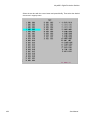
5.11.10.2
C4fx for KayakDD™ System with 4 DPM Channels per M/E and Advanced Effects Option
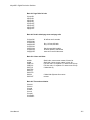
Bank 00: Push on/off
QUAD-ON
C12sl-LR
C12sl-RL
C12sl-TB
C12sl-BT
QUAD-OFF
C21sl-LR
C21sl-RL
C21sl-TB
C21sl-BT
Brings all 4 channels in from corners
Slides C1 off screen, slides C2 on screen
Slides C1 off screen, slides C2 on screen
Slides C1 off screen, slides C2 on screen
Slides C1 off screen, slides C2 on screen
Removes all 4 channels to corners
Slides C2 off screen, slides C1 on screen
Slides C2 off screen, slides C1 on screen
Slides C2 off screen, slides C1 on screen
Slides C2 off screen, slides C1 on screen
Bank 10: Reduced size effects (over shoulder position)
Wipe12sq
Wipe21sq
Wipe21LR
Wipe12LR
pgt12
pgt21
pgr12
pgr21
Square wipe reveals 2 over 1
Square wipe removes 2 from 1
Wipes 1 from 1
Wipes 2 over 2
Page turn adds 2
Page turn removes 2
Page roll adds 2
Page roll removes 2
Bank 20: Page Turns full size
K12pg-ON
C1pgt-ON
C2pgt-ON
C3pgt-ON
C4pgt-ON
C1pgt-OFF
C2pgt-OFF
C3pgt-OFF
C4pgt-OFF
K12pg-OFF
250
Double sided page turn 2sec.
User Manual
KayakDD - Digital Production Switcher
Bank 30: Page Rolls full size
C1pgr-ON
C2pgr-ON
C3pgr-ON
C4pgr-ON
C1pgr-OFF
C2pgr-OFF
C3pgr-OFF
C4pgr-OFF
Bank 40: Double sided page turns and page rolls
C12pgt-ON
C34pgt-ON
C12pgt-OFF
C34pgt-OFF
C12pgr-ON
C34pgr-ON
C12pgr-OFF
C34pgt-OFF
All effects are 2 seconds
Key 1 is front, K2 back
Key 3 is front, K4 back.
May be used with keyable
sources. Make K1 and K2 the
same or K3 and K4 the same.
Bank 50: Cubes and Slabs
smlcub
smlslb
CUB-R12
CUB-R21
SLB-TLC
SLB-TRC
SLB-CTL
SLB-CTR
SLB-IN
SLB-OUT
Small cube, centre screen rotates 3 times. 8s.
Small slab, centre screen rotates 3 times. 8s.
Full size cube. C2 replaces C1- rotate to see C3 top
Full size cube. C1 replaces C2- rotate to see C3 top
6 sided slab fly
6 sided slab fly/rotate from centre
reverse
Bank 60: Tiles and modulation
C1twinH
C1twinV
C1quad
C12twin
C1mod
C1expld
C1slitsON
C1slitsOFF
User Manual
251
KayakDD - Digital Production Switcher
5.11.10.3
Notes
5.11.10.3.1 Use of GLOBAL Channel
Although GLOBAL channel is supported, certain aspects may behave unintuitive.
Most of the effects in these libraries do not use GLOBAL, but cubes and push/pull
effects do. You may find that when you first load the effects library some effects are
not running as intended. Before running any effects go to the menu DPM – Misc Reset to Defaults and reset ALL PARAMS.
If some effects still run incorrect, be confident that there will be a software update
shortly. It may be that another version of effects library will be required at that time.
5.11.10.3.2 Format
All effects in this library are built for 4:3 aspect ratio.
5.11.10.3.3 Standard
The effects in this library are built in 625/50 standard. The effects durations are stored
internally in a format that allows the system to recalculate the duration for 525/60
standard. Effectively that means that effects do not need to be re-built for use in
525/60 standard.
252
User Manual
KayakDD - Digital Production Switcher
5.12
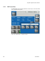
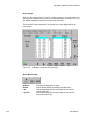
RAM Recorder Menus
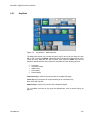
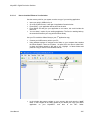
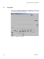
You access the RAM Recorder menu via the Home Menu.
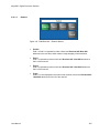
Figure 177
Home Menu
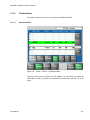
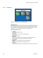
The RAM Recorder is a solid state video server with 4 input/output channels. This
means that all stills and clips are stored within a common data pool and may be
accessed by all 4 output channels.
For a 1 ME switcher the total amount of storage is 16 seconds. In current software this
is segmented for 100 stills and 12 seconds of clip video. (In 50Hz).
For a 2 ME switcher the total storage is 32 seconds, segmented as 100 stills and 28
seconds of clip video. (In 50Hz).
NOTE!
KayakDD RAM Recorder reserves 4 seconds for Stills that only 12 seconds live
video is available!
User Manual
253
KayakDD - Digital Production Switcher
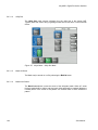
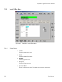
5.12.1
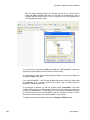
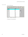
Stills Menu
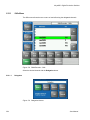
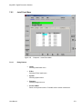
The Stills menu allows the user to store or load stills using the delegated channels.
Figure 178 RAM Recorder - Stills
Select the desired channel with the Delegation button.
5.12.1.1
Delegation
Figure 179 Delegation Buttons
254
User Manual
KayakDD - Digital Production Switcher
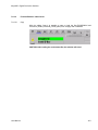
5.12.1.2
Readout
Figure 180 RAM Recorder – Readout Buttons
User Manual
•
Field1/2
Field 1 or field 2 is replicated to make a frame and Previous Still /Next Still
advances to the next field, which results in single stepping in field resolution.
•
Field 1
Field 1 is replicated to make a frame and Previous Still / Next Still advances to
field 1 of the next still.
•
Field 2
Field 2 is replicated to make a frame and Previous Still / Next Still advances to
field 1 of the next still.
•
Frame
Fields 1 & 2 are displayed in the normal order to show a frame and Previous Still
/ Next Still advances to field 1/2 of the next still.
255
KayakDD - Digital Production Switcher
5.12.1.3
Vid/Key Mode
Figure 181 RAM Recorder – Vid/Key Mode Buttons
Vid/Key Mode button
When this button is active each video signal will have an associated key signal stored
too. At recall the key signal will only be recalled if the Vid/Key Mode button is active.
RAM 1 uses RAM 2 as its associated key channel for record and recall, while RAM 3
uses RAM 4. For more information please see the Config/Misc. menu.
Stills Video/Key Mode: Video
•
•
•
•
•
•
•
256
Load Still
Load still into delegated channel.
Record Still
Grab the still from the input of the delegated channel.
Rename Still
Rename the selected still.
Delete Still
Delete the selected still. If the still contains of video and key both parts are
deleted, because a key part cannot exist without its video part.
Previous Still
Load the previous available still into the delegated channel.
Next Still
Load the next available still into the delegated channel.
E/E (E to E)
If selected show input signal of the delegated channel, otherwise the loaded still.
User Manual
KayakDD - Digital Production Switcher
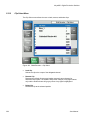
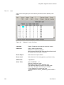
Stills Video/Key Mode: Video/Key
In this mode Ram1+2 (Ram3+4) work together as a video/key pair. Ram1 and Ram3
are always the video path and Ram2 and Ram4 are the Key path.
•
•
•
•
•
•
•
Load Still
Load the video part of the still into Ram1 (Ram3) and the key part into Ram2
(Ram4). If a still without key was selected, Ram2 (Ram4) will still show the
previously loaded still (shown as yellow selection)
Record Still
Grab the video part from the input of Ram1 (Ram3) and the key part from the input
of Ram2 (Ram4)
Rename Still
Rename the selected still
Delete Still
Delete the selected still. If the still contains of video and key both parts are deleted
Previous Still
Load the previous available video into Ram1 (Ram3) and the according key part
into Ram 2 (Ram4). If this still does not have a key part, Ram2 (Ram4) will still
show the previously loaded still (shown as yellow selection)
Next Still
Load the Next available video into Ram1 (Ram3) and the according key part into
Ram 2 (Ram4). If this still does not have a key part, Ram2 (Ram4) will still show
the previously loaded still (shown as yellow selection)
E/E (E to E)
If selected show input signals of both channels, Ram1 and Ram2 (Ram3 and
Ram4) otherwise the loaded Stills.
Figure 182 RAM Recorder – Stills
User Manual
257
KayakDD - Digital Production Switcher
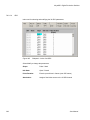
5.12.2
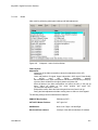
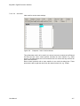
Clip Select Menu
The Clip Select menu allows the user to load, rename, and delete clips.
Figure 183 RAM Recorder – Clip Select
258
•
Load Clip
Selects the clip to the output of the delegated channel.
•
Rename Clip
Renames the default clip name and makes automatic name changes for
associated key signals. The software will prevent changes in key signal names
only and the rename button will go grey when a key signal is highlighted.
•
Delete Clip
Deletes the clip at the selected position
User Manual
KayakDD - Digital Production Switcher
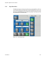
5.12.3
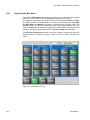
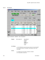
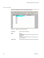
Clips Play Menu
The Clips Play menu provides the control for playing a clip.
Figure 184 RAM Recorder – Clips Play
User Manual
Begin
Moves clip to the beginning
End
Moves clip to the end
<
Play Reverse
>
Play Forward
Step - / Step +
Advances one field or frame, depending on Readout mode
Still
Goes to stop, displaying the current image
E/E
Goes to stop, showing the input signal of the delegated channel
Var
Variable speed, adjustable by the digipot
259
KayakDD - Digital Production Switcher
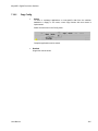
Modify
Allows you to modify the values displayed in the main display area
Figure 185 Modify Buttons
Go to timecode
Go to a timecode specified by the numeric popup panel
Mark In
Set a Mark In point via numeric popup panel
Mark Out
Set a Mark Out point via numeric popup panel
Offset
Used in Extended Loop mode
Used in Delay Line mode (not yet supported)
Mode
VTR
Standard behavior like a tape machine
Clip
Mark In and Mark Out limit the accessible timecode range. When you press play
the clip is always played from Mark In to Mark Out.
Simple Loop
Mark In and Mark Out limit the accessible timecode range. When you press play
the clip starts at the current position, plays to Mark Out and executes then total
range from Mark In to Mark Out n times, where “n” is the numbers of loops (0 =
for ever).
Extended Loop
The looped section is from Mark In to Mark Out as is the case for Simple Loop
mode, but in this mode play may start before Mark In and Offset determines the
post Mark Out play duration.
260
User Manual
KayakDD - Digital Production Switcher
5.12.3.1
Readout
In Still mode
•
Field 1: Field 1 is replicated to make a frame and Previous Still / Next Still
advances to field 1 of the next still
•
Field 2: Field 2 is replicated to make a frame and Previous Still / Next Still
advances to field 1 of the next still
•
Frame: Field 1 or Field 2 is replicated to make a frame and Previous Still / Next
Still advances to field 1/2 of the next still
•
Field1/2 Field 1 or field 2 is displayed and Previous Still / Next Still advances to
the next fields, which results in single stepping in field resolution.
While playing
•
Field 1: Only field 1 is played out resulting in “Film look”
(only 25/30 motion updates per second)
•
Field 2: Only field 2 is played out resulting in “Film look”
(only 25/30 motion updates per second)
•
Frame: Standard play out mode
•
Field1/2: This mode is useful when a still or clip is made from a graphic source
which has generated motion which is not in the expected field dominance. By
stepping to Field 2 by pressing Previous Still / Next Still, before playing a clip, the
display order of fields is reversed to F2/F1 using this mode.
Loops
Used in Loop mode to specify the number of loops to be executed (0 = for ever)
User Manual
261
KayakDD - Digital Production Switcher
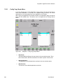
5.12.4
Clips Record Menu
The Clips Record menu allows the user to create or re-record clips.
To create a new clip, press the Record New button. Recording starts immediately and
the clip name is set to a default name. To stop recording press Still or E/E.
The Record Edit button allows you start recording in an existing clip at the current
position. The system allows recording over the end of the current clip which results in
appending to the current clip.
Figure 186 RAM Recorder – Clips Record
262
User Manual
KayakDD - Digital Production Switcher
Trim
This function is used to select the exact range out of a recorded clip, e.g. to create an
endless loop without any disturbance. When pressed the total clip is trimmed to the “In”
and “Out” values.
Delay Line
When switched on, the according channel behaves like a delay line, the desired delay
can be specified via Modify/Record Length.
NOTE!
When you change the Record Length value while you are in Delay Line mode the new
value is not accepted unless you leave and re-enter this mode.
User Manual
Begin
Moves clip to the beginning
End
Moves clip to the end
</>
Play Reverse / Play Forward
Step - / Step +
Advances one field or frame, depending on Readout mode
Still
Stops replay and displays the current image as a frame or
field depending on Readout mode.
E/E
Goes to stop, showing the input signal of the delegated
Channel
Var
Variable speed, adjustable by the digipot
263
KayakDD - Digital Production Switcher
5.12.5
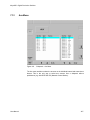
RAM Recorder Live Mode Menu
Selecting the Live Mode button (left of the display) reduces the number of parameter
adjustments to the most essential ones, allowing faster control with less selection
steps.
By pressing the button during RAM Recorder operation, a keypad with direct access to
the stored stills and clips appears.
Figure 187 RAM Recorder – Live Mode Stills Recall
Stills Recall
•
Select the according Ram channel via Delegation
•
Select the group of stills, e.g. 0-19
•
Select Video or Video/Key mode.
1. Video Mode
Only the video part of the still is loaded in the selected channel
2. Video/Key Mode
In this mode Ram1+2 (Ram3+4) work together as a video/key pair. The video
part of a still is loaded in Ram1 (Ram3) and the key part of a still is loaded in
Ram2 (Ram4). If a still does not contain a key part, only the video part will be
loaded into Ram1 and Ram2 keeps its previous image.
264
User Manual
KayakDD - Digital Production Switcher
NOTE!
Stills containing video and key are displayed in yellow characters, video only in
white.
In this Live-Menu the “Key-Only” video/key mode (only used for recording) is not
supported.
User Manual
265
KayakDD - Digital Production Switcher
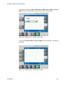
5.12.6
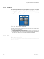
RAM Transfer Menu
The RAM Transfer menu provides possibilities to transfer clips or stills from/to RAM
store or USB flash memory sticks:
Figure 188 RAM Recorder – Clips/Stills Transfer
266
User Manual
KayakDD - Digital Production Switcher
In the different submenus (Stills to USB, Stills to RAM, Clips to RAM and Clips to
USB) the clips or stills are listed, can be renamed and the transfer started.
Figure 189 RAM Recorder – Transfer Stills to USB
In the submenu Stills to RAM and Clips to RAM clips and stills stored in the RAM can
be deleted.
Figure 190 RAM Recorder – Transfer Stills to RAM
User Manual
267
KayakDD - Digital Production Switcher
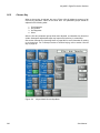
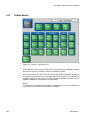
5.13
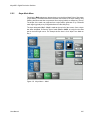
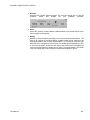
E-Mem Menus
Figure 191 E-Mem – Define Memo PP
The Define Memo menu serves to define the function groups of the KayakDD switcher,
which are be stored or recalled in an E-Mem snapshot or timeline.
The top level buttons; PP, ME1, Misc Int and Misc Ext allow group enable or disable of
the single functions named in the sub-menu relevant to the group on a keyframe by
keyframe basis.(See next figures.) In each sub-menu individual functions may be
enabled or disabled on a keyframe by keyframe basis.
NOTE!
The selection of recorded functions made in Define Memo menu for any E-Mem will
only be honoured at recall if AUTO-RECALL is enabled.
268
User Manual
KayakDD - Digital Production Switcher
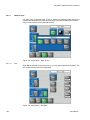
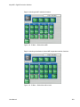
Page for selecting the ME1 switcher functions:
Figure 192 E-Mem – Define Memo ME1
Page for selecting miscellaneous internal ME independent switcher functions:
Figure 193 E-Mem – Define Memo Misc Intern
User Manual
269
KayakDD - Digital Production Switcher
Page for selecting miscellaneous external switcher functions:
Figure 194 E-Mem – Define Memo Misc Extern
270
User Manual
KayakDD - Digital Production Switcher
5.14
Media Player Menus
The Media Player menus serves to control external VTRs or other Media Servers.
The KayakDD offers a set of protocols that allow the user to connect and control
virtually all video servers, disk recorders, and VTRs on the market.
The protocols to select from are:
•
•
•
•
•
BVW75 (industry standard VTR protocol)
Mediapool
Odetics
VDCP (aka Louth), there are specialized versions for the Profile™ server family.
Pbus
With these protocols the KayakDD can control:
•
•
•
•
VTRs (BetaCam, DVCPro, etc.)
Video Servers
Disk Recorders
other media players
The list of servers that have at least one of the protocols implemented includes:
•
•
•
•
•
•
•
•
Thomson Grass Valley: Profile, Profile XP, M-Series
Thomson: Nextore
Philips: Mediapool™
Leitch (ASC): VR300, VR400
DVS: ProntoVision, etc
Sea Change
Pinnacle: MediaStream (HP), Thunder
Pluto
Disk recorders that have at least one of the protocols implemented include:
•
•
•
•
•
Accom: Attache, WSD
Abekas: A66, Diskus
Edifis: Brick, Sting
Fast Forward Video: Omega deck
…
Several of the DDRs and Servers listed offer more than one protocol. In many cases
Odetics and VDCP. The set of implemented functions may differ. Please refer to the
respective manufacturer's documentation to find out which of those protocols is more
suitable for your application.
User Manual
271
KayakDD - Digital Production Switcher
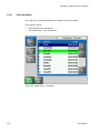
5.14.1
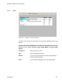
Clip Select Menu
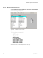
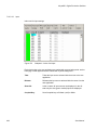
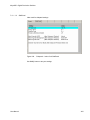
In the clip menu a clips list generated from a media server can be loaded.
Color coding in the list:
•
•
Green marked clips: selected clip
Blue marked clips: next selected clip
Figure 195 Media Player – Clip Select
272
User Manual
KayakDD - Digital Production Switcher
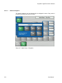
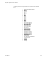
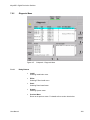
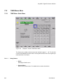
5.14.2
Clips Play Menu
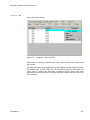
The Clips Play menu allows the user to control the connected machine.
Figure 196 Media Player – Clips Play
User Manual
273
KayakDD - Digital Production Switcher
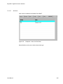
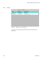
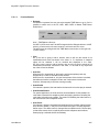
5.14.2.1
Machine Delegation
The external machines can be selected with the delegation buttons. Gang mode is
possible by selecting more than one button.
Figure 197 Media Player – Delegation
274
User Manual
KayakDD - Digital Production Switcher
5.15
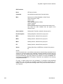
Other Menus
As the KayakDD software is enhanced, additional menus, subcategories, and controls
will become available. Once you understand the principles of KayakDD system menu
organization and operation, you will be able to quickly learn these new menus and use
them effectively for your work.
User Manual
275
KayakDD - Digital Production Switcher
276
User Manual
KayakDD - Digital Production Switcher
6
System Operation
6.1
Introduction
The basic KayakDD system is operated using button and lever control on the control
panel, and touch screen and knob controls on the Menu panel. Text and number entry
is also possible via a popup keyboard.
The Main control panel is used during live operation for fast, real time control. The
menus are generally used in conjunction with the panel controls to set up effects and
for system configuration. Since some adjustments and selections can only be
performed via menu, a special live mode is available for same menus, allowing limited
– but fast access.
Effects can be saved for future immediate recall, allowing fast and precise control of
complex visual effects in real time.
For advanced control a Sidepanel program is available which can run on a computer
with operating system Windows95 or higher.
User Manual
277
KayakDD - Digital Production Switcher
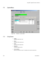
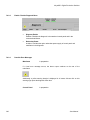
6.2
Matte Menu Controls
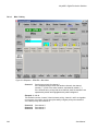
Use the following procedure to change matte settings in any of the Matte menus.
•
Go to the according Mattes menu.
•
If not already selected, touch the Wash Control data pad to bring up the Wash
Source selection and the control for Size/Offset and Softness via digipot
controls.
•
If necessary, use the Size/Offset and Softness knobs to make the wash edge
visible on the screen.
Size/Offset
Normally this parameter is named Size. When you are e.g. adjusting the Border Matte
for a wipe generator for a background transition, which uses the same wipe generator
for wash control as is used for the wipe transition itself, it is named offset.
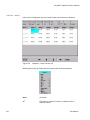
Figure 198 Matte Menu, Wash Control Selected
278
User Manual
KayakDD - Digital Production Switcher
•
•
Touch the Base Color data pad and use the top three digipots to adjust Hue,
Saturation, and Luminance of the base fill color (Figure below).
Touch the Wash Color data pad to delegate the digipots on the right to adjust Hue,
Saturation, and Brightness of the wash fill color.
Figure 199
User Manual
Matte Menu, Base Color Selected
279
KayakDD - Digital Production Switcher
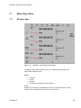
6.3
Keyer Priority
Video switchers with only two keyers per bank use a simple key over, key under
mechanism to control the stacking of the keys. Only one key can be located over the
other. The KayakDD system has four keyers, so more complex stacking is possible.
Keys can be placed between other keys, using key priority.
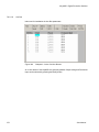
6.3.1
To Change the Current Keyer Priority
1. Go to the Keyer – Priority menu by touching the Keyer button in the Home
menu, then touch the Priority/Misc category selection button
Figure 200 Keyer Priority Menu, Current Stack Selected
2. If not already set up, turn on the desired keys and arrange them so they
overlap, observing the Program monitor. This will make the changes in key
priority visible. For demonstration purposes, you can use four preset pattern
keys.
3. Touch the keyer you wish to move in the stack in the Current column, then use
the Top, Move Up, Move Down, and Bottom buttons on the left to place the key in
the desired location. The key priority order changes immediately, as a cut.
280
User Manual
KayakDD - Digital Production Switcher
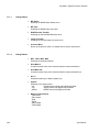
6.3.2
To Transition Between Different Keyer Priorities
Key priority transitions use a Current priority stack and a Next priority stack. The
transition occurs between the two stacks.
1. Press the Key Prior Transition element button in the Transition subpanel
Transition Subpanel
BGD
Key1
Key2
Key3
Key4
FTB
Enbl
Key
Prior
Dve
Black
Pst
Cut
Add
Mix
Wipe
Auto
Trns
Pvw
2. If not already set up, turn on the desired keys and arrange them so they
overlap, observing the Program monitor. This will make the changes in key
priority visible. For demonstration purposes, you can use four preset pattern
keys.
3. Delegate that M/E for preview in the Preview subpanel. This shows the end
result of the transition (the Next priority).
4. Go to the Keyer-Priority menu by pressing the Keyer button in the Home menu,
then touch the Priority/Misc category selection button.
5. The current stack in the menu is automatically set to what is currently being
output. You can change the Current priority stacking order if desired, as
described
in
To
Change
the
Current
Keyer
Priority.
6. Set up the Next priority stacking order, selecting the keyers in the Next column
and then using the Top, Move Up, Move Down, and Bottom buttons (Figure
below). The new stack will be visible on the preview monitor.
User Manual
281
KayakDD - Digital Production Switcher
Figure 201 Keyer Priority Menu, Next Stack Selected
7. Select the type of transition, using the Mix or Wipe buttons in the Transition
subpanel. If you selected a wipe, go to the Wipes menu by double pressing
one of the Wipe buttons, and then touch the pattern and any modifiers to be
used with the wipe.
8. Move the lever arm or press the Auto Trans button in the Transition subpanel
to perform the key priority transition. The transition is shown on the Program
monitor.
282
User Manual
KayakDD - Digital Production Switcher
6.4
Chroma Key Operating Notes
The KayakDD system features chroma keyers with powerful controls. These controls
offer subtle adjustments to allow successful keying of difficult subject matter (fine hair,
smoke, translucent objects, etc.), and to overcome some problems resulting from
imperfect chroma key set coloring or lighting.
Section - Concepts of the KayakDD this Manual - includes chroma key background
information useful for understanding the chroma key controls. The following
information provides more detailed instructions on how to set up a chroma key using
the Auto Setup feature and the manual controls in the Keyer menu.
6.4.1
Auto Setup
The first step of setting up most chroma keys is to use Auto Setup. Auto Setup
automates the first steps to achieving a chroma key. Auto Setup performs the
following:
•
•
•
•
•
•
Calculates primary suppression Hue and Luminance.
Sets primary suppression Selectivity and Chroma to defaults.
Calculates Clip Low, and sets Clip Hi to default.
Sets all the secondary suppression values to duplicate the primary
suppression values, but turns secondary suppression off.
Changes Opacity temporarily to 100% to permit an accurate backing color
sample, and then returns it to its original setting.
Sets Key Position and Size values to default (0).
Two different Auto Setup algorithms are available, one for well designed and lighted
sets (FGD Fade off), and the other for more challenging sets (FGD Fade on). Depending
on individual circumstances, additional manual adjustments may be required after you
use Auto Setup.
After an Auto Setup has been initiated, you can cancel it by pressing the Auto Setup
button again, but the chroma key will retain the default settings imposed.
User Manual
283
KayakDD - Digital Production Switcher
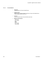
6.4.2
To Chroma Key Using Auto Setup
1. Go to the Keyer – Mode menu by touching the Keyer button in the Home
menu, then touch the Mode category and select Chroma Key as key mode.
2. Choose on the selected keyer’s key bus the chroma key source containing the
chroma key backing color.
3. Choose on the Program bus the source that will be used to replace the
backing color of the chroma key source.
Figure 202
Keyer Menu, Chroma Keyer
4. Press the Auto Setup button or the Positioner button on the top of the joystick.
Preview for that M/E will now display the chroma key source with a
superimposed cross hair cursor. The cursor actually represents a box of 16 x
16 pixels.
5. Use the Positioner to position the cursor on the backing color. Select a darker
area, if one exists, to optimize the backing color suppression.
6. Press the button on top of the Positioner. The chroma key will be set up
automatically using the average of the colors selected by the cursor box. If
FGD Fade was off, fine edges of the key will be preserved.
284
User Manual
KayakDD - Digital Production Switcher
7. If this chroma key is acceptable, you are done. If set, lighting, or other
conditions prevent the result from being acceptable, you need to decide
whether to adjust the chroma key manually or use Auto Setup with FGD Fade
on.
•
•
6.4.3
Manual adjustment permits retention of fine edge detail (see Manual
Chroma Key Adjustments). In particular, if there are problems with
translucent areas (hair, smoke) secondary suppression controls can
be useful (see Secondary Color Suppression).
Auto Setup with FGD Fade on produces a chroma key with harder
edges, but accommodates wider set variations (see below).
To Chroma Key Using Auto Setup with FGD Fade
If the set is lit unevenly or has other problems, FGD Fade is available to help solve the
problem. A better alternative, if time permits, is to adjust the lighting on the set to even
out the backing color. This may improve the key so that FGD Fade is not needed.
1. If you decide you must use FGD Fade, follow the Auto Setup procedure
described above, but set FGD Fade on in the Keyer menu. After selecting the
backing color area and touching the top button on the Positioner, the chroma
key will be set up with coarser values better able to handle set variations.
2. If this chroma key is acceptable, you are done. If you are still not satisfied, you
can fine tune the chroma key using manual adjustments.
6.4.4
Manual Chroma Key Adjustments
If the Auto Setup of the hue fails to provide a suitable chroma key, additional controls
are available in the Keyer Menu for fine tuning the key.
Chroma key manual set up consists of choosing the best set of compromises to
provide adequate detail and color fidelity to meet your needs. While using this menu
you need to view the chroma key scene on a monitor. A vectorscope and waveform
monitor can also be very useful when setting up a chroma key. During set up you need
to focus your attention on particular areas of the foreground, background, and/or
composite. The areas you look at will change depending on the individual controls
being used.
Via the popup button Output you can select FG Only or BG Only to remove extraneous
picture information, allowing you to view only those areas of the composite.
Chroma key set up procedures follow a recommended order, as indicated by the
numbered steps displayed on the menu. However, requirements can vary depending
on each individual scene. You may need to go back to earlier steps and readjust
previous settings to optimize the key. Understanding what the chroma key controls do
will help you decide what adjustments are required for your individual situation.
User Manual
285
KayakDD - Digital Production Switcher
6.4.5
Primary Suppression
Primary suppression is the most critical chroma key parameter, and the easiest to set.
Auto Setup should take care of this, but manual adjustments can be made if desired. If
primary suppression is set wrong, however, it will be impossible to achieve a good
chroma key with the other controls.
Primary Suppression should be set while looking at the foreground. Ideally the backing
color will appear as a small dot on the vector scope and a perfectly flat line on the
waveform display, but this never occurs due to set lighting variations, shadows, etc.
This means you will need to pick the best suppression for the overall look of the key.
1. Touch the 1 Prim Suppress data pads, if necessary, to activate these controls.
Data Pad 1 contains Luma / Chroma / Flare Suppression
Data Pad 2 contains Hue and Selectivity
Figure 203 Keyer Chroma Menu, Pri Suppress, Part1, Luma / Chroma / Flare S.
286
User Manual
KayakDD - Digital Production Switcher
2. Adjust Hue, Selectivity, Chroma, and Luma primary suppression to eliminate
the backing color.
•
•
•
•
•
Hue can be set accurately with Auto Setup. Hue should center on the
primary color of the backing area of the foreground scene. Depending
on where Luma and Chroma primary suppression are set, adjusting
Hue may not make any noticeable change on the scene. Chroma
suppression should be preset to 100% and Luma set to 0%. Hue can
then be tuned to remove the backing color.
Selectivity may need to be increased if there are colors in the
foreground image that are being suppressed. Selectivity should be
set as low as possible without including colors that should not be
suppressed. For example, when keying on green, a greenish yellow
shirt might be affected by the suppression. If so, adjust the selectivity
high enough to reject that color. Too high a selectivity is one of the
classic causes of a noisy key. If the foreground subject is stationary,
consider using a force mask instead of increasing selectivity.
Chroma suppression can be set accurately with Auto Setup. To
adjust, increase Chroma suppression and observe the backing color
dot on the vector scope move toward the center. You want to center it
exactly, so no chroma exists in the backing area. 100% chroma
suppression is the correct setting for all chroma keys. At this point, you
will probably see a line through the center of the vector scope. With
increased selectivity, this line will become an arc.
Luma suppression adjustments may be necessary if shading is visible
in the backing area with FG Only selected, or if the shading adversely
affects the background image. Primary Luma suppression is hardly
ever desired when FGD Fade is on. To adjust, increase Luma
suppression and observe the backing color move toward black. You
want to make the backing color just black. Increasing this control too
much will make the chroma key hard and noisy. When not enough,
highlights will be added to the background. Note that incomplete
luminance suppression is not necessarily bad. The highlights added to
the background will match the shading on the backing wall, adding
natural shadows and perhaps eliminating the need to add artificial
shadows.
All the above adjustments may need to be revisited later.
3. Another potential artifact of chroma keying is a tinting of the overall foreground
subject due to lighting splash from the backing color or lens flare. Flare
Suppression adds a small amount of color to the entire foreground image to
cancel the splash or flare. Typically less than 2% of the backing color is
needed to neutralize the flare.
User Manual
287
KayakDD - Digital Production Switcher
6.4.6
Key Controls
The purpose in adjusting Clip Hi and Clip Low is to cause the proper hole to be cut in
the background. All areas of the backing color should be full background while all
areas of the foreground should make the background completely invisible. The easiest
way to do this is to observe the key signal while making your adjustments.
The smaller the difference between Clip Hi and Clip Low, the higher the keyer gain.
High gain amplifies noise present in the transition between transparent and opaque.
The correct setting is with Clip Hi and Clip Low set to just barely achieve opacity and
transparency, respectively.
1. Touch the Key Controls data pads to activate these controls.
Data Pad 1 contains Clip Hi / Clip Low / Opacity
Data Pad 2 contains Size and Position
You can now manually adjust keyer clipping controls.
2. Press the Key PVW button on the Main control panel and look at the
preview output on a picture and waveform monitor.
Figure 204 Key Controls, Part1, Clip HI, Clip Low, Opacity
288
User Manual
KayakDD - Digital Production Switcher
3. Adjust Clip Hi so that all areas of the foreground objects are white. If Clip Hi
is set too low (too far clockwise), much of the translucent areas will be
forced to be fully opaque, hardening the key and darkening the transition
area between background and foreground.
4. Clip Low can be set accurately with Auto Setup. Adjust Clip Low so that
all areas of the backing color are black. If Clip Low is set too high (too far
counter-clockwise), translucent areas will be forced fully translucent,
hardening the key.
NOTE!
When adjusting clip levels, remember that areas on the edge of the
foreground subject should show as shades of gray. Gray indicates areas
of translucency, which is desirable in chroma keying.
5. Check the final results with Key PVW off and the chroma keyer in normal
mode (FG Only turned off). Note that incorrect adjustments can create a
hard, noisy key.
6. If the chroma key now looks good, you are done. If dark edges are
present, there may be too much primary Luma suppression or Clip Hi or
Clip Low may be set improperly. If adjusting these parameters fails to solve
the problem, you should consider activating the Reshape feature.
6.4.7
FGD Fade
FGD Fade is useful when shading variations exists in the backing color. A better
alternative, if time permits, is to adjust the lighting on the set to even out the backing
color. This may improve the key so that FGD Fade is not needed. FGD Fade helps
with backing color suppression at the expense of a harder looking key with more
noticeable edge artifacts. A drawback of FGD Fade is loss of detail in the keyed edge.
For example, smoke and hair in the foreground will probably be lost.
1. Touch the FGD Fade button to activate this feature.
2. Set primary Luma suppression to 0.
3. You can now readjust the Clip Hi and Clip Low controls if necessary to fine
tune the key as described above.
4. When FGD Fade is on, key resizing and positioning also become available to
clean up the key edges.
•
•
User Manual
Size narrows the key signal and can remove much of the blue or green
edge on the foreground subject.
Position moves the key signal left and right, and can be used to
reduce a color edge along only one side of the foreground.
289
KayakDD - Digital Production Switcher
6.4.8
Secondary Color Suppression
Secondary color suppression is intended to improve the color of translucent areas
(e.g., glass or smoke) or fine detail near the edge of a foreground subject (e.g., hair).
These areas can be take on some of the backing color.
Much less secondary suppression will be needed than is used for primary suppression,
because the foreground color is only partially corrupted by the backing color. Because
there is a mixture of backing color and foreground color, the secondary suppression
Hue and the direction (Angle) will be different from primary suppression. Primary
suppression removes the backing color, while secondary suppression corrects the
color in translucent areas.
NOTE!
If FGD Fade has been applied, it is unlikely enough edge detail will remain to use
secondary color suppression.
1. Touch the Sec Suppress data pads and then touch the Sec Suppr. button to
activate this feature (Figure below).
- Data Pad 1 contains Luma / Chroma / Angle
- Data Pad 2 contains Hue and Selectivity
Figure 205 Sec Suppress Controls Part1, Luma / Chroma / Angle
290
User Manual
KayakDD - Digital Production Switcher
2. Adjust secondary suppression Hue and Selectivity so that the translucent area
is affected, but opaque areas of the foreground are not. The final hue will lie
somewhere between the backing color (primary suppression hue) and the
uncorrupted foreground color.
3. When making this adjustment, it is helpful to turn the secondary Chroma
Suppression to maximum, and the secondary Suppression Angle to produce an
unnatural color in the affected area. This makes the changes to secondary
suppression more obvious.
4. Selectivity should be kept as wide as possible. You should only narrow
selectivity (increase its value) if you cannot avoid changing opaque areas of
the foreground.
5. Adjust the secondary Angle so that changing secondary Chroma suppression
moves the color in the desired direction. You are trying to match the color of
the translucent areas to an opaque (uncorrupted) area of the foreground
subject.
6. Decrease secondary Chroma suppression for the best match between
corrupted (translucent) and uncorrupted (opaque) areas. Interaction between
secondary suppression Angle and Chroma suppression may require repeating
these adjustments.
7. Increase secondary Luma suppression to balance lightness of the translucent
and opaque areas.
8. Repeat secondary suppression Angle, Chroma suppression and Luma
suppression for best results.
User Manual
291
KayakDD - Digital Production Switcher
6.4.9
Other Chroma Key Controls
Additional chroma key controls are available by touching the Other data pads (Figure
below). Coring, fringe, and shadow controls can be individually activated by touching
the labeled buttons.
Data Pad 1 contains Shadow Clip / Shadow Gain / Shadow Opacity
Data Pad 2 contains Coring and Fringe
Figure 206 Other Controls Part1, Shadow Clip / Shadow Gain / Shadow Opacity
Coring replaces any pixels in the luminance signal after primary suppression that are
below the adjustable threshold with black. This eliminates noise resulting from
incomplete suppression. While coring can improve some keys, it can easily be over
done. Coring thresholds much above black will affect dark grays that are actually part
of the foreground subject, making the chroma key composite look unnatural.
Fringe is used to restore color to the gray portions of the foreground color resulting from
secondary suppression adjustments. This control is only active when secondary
suppression is on.
Shdw provides controls of shadows that fall on the backing. Shadow Clip and Shadow
Gain allow selecting the range of the luminance portion of the foreground that produces
a shadow. Shadow Density is an opacity control for the shadow and adjusts how much
shadow is added to the background.
292
User Manual
KayakDD - Digital Production Switcher
6.5
Pattern Mix
The KayakDD system can combine the complex wipe pattern generators (Wipe1 and
Wipe2), to create a wide variety of customized wipes.
6.5.1
To Create a Pattern Mix
1. Double press the Wipe button in the Transition subpanel on the Main panel.
This selects Wipe as the next transition type and also opens the Wipes menu
with Wipe1 delegated for control.
2. Select the Wipe1 pattern to be used by touching the Pattern data pad, and then
selecting one of the displayed patterns.
3. Touch the Mix, Ratio, etc. data pad.
4. Press the Trans PVW button in the Transition subpanel, and move the lever arm
part way. This will display the Wipe1 pattern on preview.
5. Set Wipe delegation to Wipe2 and select the desired pattern to be mixed with
Wipe1.
6. You can select the type of pattern mix with the Mix type buttons (Mix, NAM +,
NAM ---). The NAM buttons are used for And or Or pattern mixing.
7. You can also adjust the amount each wipe pattern contributes to the mix with
the Ratio control digipot. At 50%, each pattern contributes equally. At 25%, the
other pattern contributes only 25% to the final pattern.
NOTE!
It is always Wipe1 which is adjusted for pattern mix, i.e. you are mixing Wipe1 with
Wipe2. Not Wipe2 with Wipe1.
Figure 207 Pattern Mix Menu
User Manual
293
KayakDD - Digital Production Switcher
294
User Manual
KayakDD - Digital Production Switcher
7
Sidepanel Program
7.1
Introduction
The Sidepanel program is a Windows based program, which is used a the menu part
of the Thomson Grass Valley DD35/XtenDD control system.
Since the KayakDD is also a member of this control system, the Sidepanel program
can be used to enhance the possibilities of the KayakDD switcher. More advanced
features, which you normally do not find on a switcher of this size will become
available by the use of this program.
The program will run on Windows 95 or higher operating systems.
NOTE!
Since the Sidepanel program is also used for the larger production switchers of
the XtenDD series with up to four M/E levels. Some screenshots in this manual
show additional items which are not available for the KayakDD system (e.g. more
than 16 inputs, more than 10 aux buses).
NOTE!
In some menus of the Sidepanel you may find features which are not yet
implemented in the KayakDD system or will not be available at all, due to a
different hardware structure
Due to their logic structuring and application of standard elements, the menus are
largely self-explaining. The setup is made according to the Graphical User Interfaces
(GUI) usual in the PC world. Control of the individual functions is possible with the
associated softkeys as well as with a mouse.
The following sections serve as an introduction into the philosophy of menu control,
describing only the most important elements. Detailed information concerning the
individual menus is contained in the following chapters of the manual.
User Manual
295
KayakDD - Digital Production Switcher
7.1.1
Sidepanel Glossary
Button
Control element of the graphical user interface which in appearance
and function corresponds to a button. Such as on/off-buttons,
action buttons, etc.
Control Element All graphic elements of the user interface that are able to react to
user inputs.
Dialog Elements All graphic elements of the user interface.
7.1.2
Dialog Button
Dialog keys are the 6 buttons to the left of the display. They are
used for the selection of other control dialogs. The graphic
equivalent on the display is the dialog button.
Menu Button
Buttons on the sidepanel keyboard for the selection of primary
control dialogs.
Digipot
Control element for adjusting analog values
What’s a Sidepanel Menu
All sidepanel keyboard hardware controls (digipots, function and dialog buttons)
have an associated control element within the display. This control element is
placed as near as possible to the hardware control. The control elements belonging
to the softkeys have two tasks:
•
•
Identify the function of the control
A mouse click on the control element results in the same action, like pressing
button.
The controls belonging to the digipots describe the function of the digipots. Every
dialog of this format is called a menu. Associated functions are grouped whenever
possible. A group of co-operating analog controls is formed by stacking up to four bar
graphs into one column. If a menu has more than one bar graph column the column
must be mapped (delegated) onto the digipots. This delegation is done when the
grouped functions are activated (e.g. ”Mask On” or ”Border On”) from this menu or with
any other key belonging to the same function group. When an analog control column is
delegated, the digipot designators are updated.
The menus are structured using mainly 3D effects to provide a clear and appealing
user interface without using many colors. Colors are used to signal events or represent
states.
The inner dialog area is used for visualization of parameters and for setting parameters
with the mouse. E.g. analog settings are represented by bar graphs inside the inner
dialog area.
296
User Manual
KayakDD - Digital Production Switcher
A definition of the various areas of a control dialog is given in the following diagram:
Figure 208 Sidepanel Menu Structure
7.1.3
Color Coding
Red
Medium blue
Green
Light blue
Yellow
Light grey
Dark grey
Black
White
White
User Manual
Attention (as the traffic signboard)
Active bars in bar-graphs
ON state in the case of on/off buttons
marking of the active field in listboxes
Attention
Background
Inscription (inactive), shadow edges
Inscription (active)
Bright edges
Background of delegated bar graphs
297
KayakDD - Digital Production Switcher
7.1.4
Fixed Softkeys
These buttons have the same function in most menus:
This button opens a button-overlay for direct selection of a similar hardware resource.
7.1.4.1
Delegation
NOTE!
The overlay is displayed in default for approx. 5 seconds. The time
can be changed in the menu Personality / Sidepanel!
7.1.4.2
Transfer
This button opens a button-overlay for the available transfer modes ”Transfer
from”, ”Transfer to”, ”EXCHANGE with”, and “Undo”.
NOTE!
The overlay is displayed for approx. 5 seconds. The time can be
changed in the menu Personality / Sidepanel!
Example: Transfer of the wipe settings from M/E1, wipe 1.
Step 1: Select Transfer
Step 2: Select From
Step 3: Select M/E1
Step 4: Select Wipe1
298
User Manual
KayakDD - Digital Production Switcher
7.1.4.3
Lock Menu
As long as this button is switched on, the Auto Menu function is inhibited.
7.1.4.4
Digits
This button is an on/off key that controls the numeric readout of analog values. The
default setting of this button is a personality preference. A ”double click” on this button
enables the numeric keypad.
7.1.4.5
Previous Menu
Recall the previous menu. Pushing Previous Menu again returns the operator to the
menu they just left.
User Manual
299
KayakDD - Digital Production Switcher
7.1.5
Bar Graphics
A bar graph visualizes parameters with a continuous (analog) range of values. A bar
graph is also used to adjust settings with a number of distinct values. It is assumed
that the average user associates a potentiometer and not a switch with the setting.
A bar graph has the control state relevant/irrelevant and delegated/nondelegated
which is represented optically. A bar graph in the delegated state is represented a blue
color. An non-delegated diagram is shown in black and an irrelevant diagram shows
only the frame and the text in gray color. The column and the numerical values are not
shown.
Bar graph in digit view mode. The bar graph contains the numerical value and the unit
of the parameter. A mouse click into this field enables numeric entry via a keyboard
connected to the panel.
300
User Manual
KayakDD - Digital Production Switcher
7.1.6
Digipot Designator
A digipot designator is a control element which is used to describe the digipot function.
It is represented in the digipot area on the right side, in each case in the height of the
pertinent digipot. The inscription changes if another group is selected.
A numeric digipot designator has a small bar to give an overview of range and actual
position of the value. This bar cannot be operated with the mouse, but you can enter
the numeric value via the keyboard.
If the user turns the digipot slowly, it works in a linear mode. This means that the
number of increments is proportional to the rotated speed of the digipot. If the user
turns the digipot fast, the function will be nonlinear (e.g. quadratic).
7.1.7
Selection Box
A selection box is a control that shows a number of elements. All elements of the
group are inside a frame. In the upper frame the name of the group is shown. One
element in the group is always selected. An element has a name or a bitmap as
description.
Examples of selection boxes. The left three boxes are the default boxes. The right
three boxes are optional (Personality Setup). Blocks and Multi are delegated. The
Shape is non-delegated. A selection box can be controlled with the mouse or with a
digipot if the box is delegated. When the user clicks to an unselected element the
element is now selected. With the digipot the selection can moved up and down.
User Manual
301
KayakDD - Digital Production Switcher
7.1.8
List Boxes and Index Cards
Listboxes are used to display and change lists of values. Most setup menus will have
listboxes. A menu that uses a listbox must have cursor keys, a ”Click” key Modify and
a select key OK. The digipots can also be used for listbox cursor positioning (digipot 0
for Up/Down and digipot 1 for Right/Left). Also the mouse can be used to position the
cursor. The cursor follows the mouse cursor. The softkeys for cursor positioning do
autorepeat when held down.
Sliderbar: If the listbox has more entries than lines, the sliderbar can be used to
position the visible section.
Every listbox has a memory for the actual listbox cursor position when the user leaves
the listbox or the menu. If the user selects the menu or listbox later the list box cursor
appears at the last stored position. Menus with more than one listbox have only one
set of control buttons. These buttons and the digipots will be delegated (with a cursor
button) to the selected listbox.
Figure 209
302
Sidepanel – List Box
User Manual
KayakDD - Digital Production Switcher
7.1.9
Typewriter
When the user is requested to make a character input, a keyboard with typewriter
layout (style US English) can be selected appear in the dialog window.
Figure 210
Sidepanel – Typewriter
There are two types of input, normal input and password input. If a password is
requested, for each typed character, a star appears. The operation of the typewriter is
possible with the following controls:
•
Keyboard that is connected to the side panel PC
•
Mouse or other pointing devices
•
Digipot control: The left-right digipot changes the cursor position in a horizontal
direction. When the cursor reaches the last button in the row it jumps to the
first button in the next row. When the cursor reaches the first button in a row it
jumps to the last button in the previous row. The top-down digipot changes the
cursor in a vertical direction. When the cursor reaches the last row it jumps to
the first row in the next column. When the cursor reaches the first row it jumps
to the last row in the previous column.
•
Numeric keypad (only for numbers)
The shift key operates like the 2nd button of a pocket calculator. If the shift key is
pressed the next character is a capital letter or a special character
(~!@#$%^&*()_+{}|:”<>? ) respectively. The label on the button changes. If the shift
lock function is active, the corresponding button will be represented as a pressed
button.
Numeric keypad of the control panel will now be activated in the following cases:
User Manual
•
Click on the EditField of a Slider
•
Click on the EditField of a Digipot, which is connected to a slider
303
KayakDD - Digital Production Switcher
Double-clicking on the digit button modifies the last Slider that was modified with the
mouse or side panel digipot.
7.1.10
Using a Mouse
The menu can also be controlled by means of a mouse. Doing so, all functions
contained in the menu are controllable with the mouse, thus enabling an operation
without softkeys and digipots. That means, operation is possible from a normal PC
without special hardware.
The functions are initiated by clicking or double-clicking with the left mouse button on
the individual elements in the menu.
Clicking with the right mouse button calls a pop-up menu which enables a change into
the other menu groups. This function replaces the menu buttons arranged to the left of
the display.
7.1.11
Dialog Title
A dialog title is presented inside the dialog area. It is edged by a graphic elevation. The
hardware resources addressed by the control dialog as well as the addressed area
come from the selection of this area. Example: hardware resource M/E1, area Main
menu. The specified M/E text (e.g.M/E1) has the M/E color coding.
Clicking the mouse into the header selects the menu for the next associated hardware
resource. For example, the control dialog of M/E1 then changes to M/E2.
304
User Manual
KayakDD - Digital Production Switcher
7.1.12
Menu Groups and Hierarchy
The root menu is the Status menu. From Status the top level menus of each group
can be selected (when clicking the right mouse button) via the pop-up menu or
pressing the respective menu buttons.
Menu group
Sub-menus
Startup
Startup
Status
Status
Status
P/P
M/E
M/E
Main
Auto Times
Color Background
Key
not supported in KayakDD
Wipe
not supported in KayakDD
Remote
Montage Proc
Remote
Remote
GP-I/O
P-Bus
not supported in KayakDD
Color Bgnd
Color BGD
Color BGD 1, 2, 3
Correction
Correction
Aux
Install
Install
Main
E-Box
Panel
System
Diagnose
Configuration
Config
Config
E–Box
Panel
Allocate Panel
Video Store
User Manual
Top level menu
not supported in KayakDD
TiM/E Memo_
TiM/E Memo
Select
Define
DVE
DVE
DVE Extern
DPM Main
DPM Edit
Media Player
M/E
MP Status
MP Clips
RamRec Transfer
Image Converter
Personality
Personality
Main
Auxiliary
Aux
Main
305
KayakDD - Digital Production Switcher
In some cases it is necessary for convenient and fast operation that a menu in the
context of an object provides a ”link” into a menu of another object.
Example: The Paint Store Menu has a link to the Wipe Main Menu if a pattern is
selected as Paint Store source. The button that activates the link has the look of a
dialog button . It shows the name of the called menu. It is located in the function
buttons area not in the dialog button area. Once the link is activated the Previous
Menu button changes to Return to provide a direct return path into the ”calling” menu.
Return is changed back into Previous Menu” when:
1. the Return is done
2. the context of the destination menu’s object is left.
Example: Paint Store has link into M/E x Wipe1 Main, the link is followed. Return is
valid as long as the user is in menus of that wipe generator. If another wipe generator
or another top level menu is selected Return is discarded and the button changes to
Previous Menu.
306
User Manual
KayakDD - Digital Production Switcher
7.2
Startup Menu
After program start, the Startup menu is shortly called with the KayakDD logo and
then automatically the menu available last with all selected parameters.
With initial startup, the Startup menu is called in order to enable selection of the main
frame and establishing the connection.
Figure 211
Sidepanel – Start Menu
The run-up bitmap (big one DD35 logo) and the background bitmap in the Startup
menu can be replaced by user defined ones. During run-up, the system is looking for
the files
•
•
c:\programme\dd35\bin\logo.bmp and
c:\programme\dd35\bin\logo2.bmp
If not available, the internal DD35 logo will be displayed. The file logo2.bmp is
optionally. If not available, the logo.bmp is used for both purposes.
User Manual
307
KayakDD - Digital Production Switcher
7.2.1
Selection of the Mainframe
Actuating the E-Box button calls a listbox in which the main frames connected to the
mains are listed with IP Net Address. After selection of a main frame, the Connect and
Disconn buttons are activated.
A corresponding selection connects or disconnects the connection.
7.2.2
Selection of a Attached Panel
Actuating the Panel button calls a listbox in which the switcher panels connected to the
mains are listed with IP Net Address. After selection of a panel, the Attach and
Detach buttons are activated.
A corresponding selection connects or disconnects the connection.
308
User Manual
KayakDD - Digital Production Switcher
7.2.3
Close / Minimize / Shut Down
User Manual
•
Close
A click (button or mouse) closes the XtenDD application.
•
Minimize
A click (button or mouse) minimizes the XtenDD GUI on the screen to the
Windows95 Task bar. A minimized state can be restored to its original size by
pressing any key
•
Shut Down
A double-click (button or mouse) closes the XtenDD application and shut down
the control panel PC.
309
KayakDD - Digital Production Switcher
7.3
Status Menu
The root menu of the switcher is the Status menu. From Status the top level menus of
other group can be selected (when clicking the right mouse button) via the pop-up
menu or pressing the respective menu buttons.
Figure 212
310
Sidepanel – Status Menu
User Manual
KayakDD - Digital Production Switcher
7.3.1
Selecting the M/E Main Menus
M/E1 - M/E2 - M/E3- P/P
Press the associated dialog button to select the associated M/E Main menu which
serves to modify the switcher parameters. In KayakDD-1 only PP, KayakDD-2: ME-1
and PP is available.
7.3.2
Enable / Disable the Faders
Fader Active: M/E1, M/E2 M/E3, P/P
Press the associated button to enable or disable the panel fader of the individual
mixing levels and the menu fader in the M/E Main menus. The active status is
displayed in the button. In KayakDD only PP is available.
7.3.3
User Definable Presets
User definable preset of the mainframe operational state is possible for a single M/E or
the complete switcher. For a recall of the complete switcher preset select the Status
menu. A single switcher preset can be recalled in the M/Ex Main menu.
Refer to the Install E-Box menu for saving the preset data.
User Manual
•
Recall Preset
The following presets can be recalled:
•
Factory Preset
Recall the factory preset.
•
Operation Preset
Recall the user defined operation preset. See section Install E-Box to store the
user defined operation preset.
•
Undo
Recall the last user settings.
311
KayakDD - Digital Production Switcher
7.3.4
Attached Macros
This menu can be accessed in two ways:
•
•
via Config / Attached Macros menu
by clicking to “attached macros” button,
which is visible in all menus at the right side between the middle digipots. This button
is only visible when there is at least one macro attachment. The button is gray or
green, depending on the settings in the menu Personality / Panel / MaKE Memo
Attachment Playmode.
312
User Manual
KayakDD - Digital Production Switcher
7.4
7.4.1
M/E Menu
M/E Main Menu
Figure 213
Sidepanel – M/E Main Menu
The inner dialog area shows the status of the respective M/E stage. All transition
functions (Cut, Auto, Trans PVW, Trans Duration, ...) can be controlled by trackball
or mouse.
User Manual
313
KayakDD - Digital Production Switcher
7.4.1.1
7.4.1.2
314
Select Trans Duration Time
•
•
Click on Duration field
Enter the desired value using the numeric keypad
•
Click E (enter) or C (clear)
•
Auto Times
For details refer to section Auto Times Menu.
•
Previous Menu
Return to the previous menu. For details refer to section Introduction.
•
Recall Preset
Recall the single M/E Preset
•
Factory Preset
Recall the factory preset
•
Operation Preset
Recall the user defined operation preset. See below to store the user defined
operation preset.
Dialog Buttons
User Manual
KayakDD - Digital Production Switcher
•
All stop
Press the associated button to stop or reset the following functions:
- stops all ongoing auto transitions
- sets FTB to inactive (100%)
- sets transition type to MIX
- moves BGND transition to start position
- removes all keyers
- set Next Transition BGND
- resets Next Transition for all other components.
This command does not
- influence matrix crosspoints
- stop TiM/E timeline play or TiM/E snapshot dissolve.
•
Menu Lock
For details refer to section Introduction.
•
Fader Active
Press the associated function button to enable or disable the fader of the
individual mixing levels. The active status is displayed in the button.
•
Curve
Press the associated function button to select the transition characteristics for
the faders.
•
•
•
•
•
Linear transition on the basis of a linear function
Expon transition on the basis of an exponential function
Gamma transition on the basis of a gamma function
S-Expon transition on the basis of an exponential gamma function
S-Gamma transition on the basis of a gamma exponential function
The selected curve function will be displayed in the button header area.
User Manual
315
KayakDD - Digital Production Switcher
•
BlkPSTMode
The BlkPST Mode button permits selection of different modes of fading:
To select a fading mode, activate the button and then select a mode with the
overlay button X-Fade, V-Fade1, V-Fade2, V-Fade3 or V-Fade4.
NOTE!
Defaults back to X fade after transition is finished.
For the V-Fade two modes of operation are selectable by clicking the listbox:
•
Trans Type
The Trans Type button permits selection of different types of transitions:
To select a transition type, activate the button and then select a transition type
with the overlay button Undef, Mix, Add, Wipe1, Wipe2 or DVE.
The selected transition type is displayed in the button header area.
NOTE!
Please note that you can only change the transition type when the transition is
finished, i.e. when an automatic transition has been completed or the fader is
in end position.
316
•
Limit Set
The Limit set and Limit on buttons serve to create reproducible partial
transitions. This mode is possible with all types of transitions. Limit set permits
storing the desired value set with the fader.
•
Limit On
Limit on enables the mode. Any transition with Cut or Auto and any manual
transition with the fader is only executed up to the value previously defined
with Limit set. If the transition is made with the fader, the yellow arrow to the
left of the fader does not change the direction when the fader is moved to its
end position, thus indicating that the transition is not completed. If Limit on is
User Manual
KayakDD - Digital Production Switcher
switched off at the point defined by Limit set, a jerk free transition to the next
contribution can be made with the fader. The remaining transition length is
then stretched to the full fader path.
7.4.2
Auto Times Menu
Figure 214
Sidepanel – Auto Times Menu M/E
The menu permits setting the auto transition times.
7.4.2.1
User Manual
Dialog Buttons
•
Main
Selecting M/E Main menu.
•
Previous Menu
Return to the previous menu. For details refer to section Introduction.
317
KayakDD - Digital Production Switcher
7.4.2.2
7.4.2.3
Function Buttons
•
Start
Starts the transition selected in the list box.
•
Trigger
Press the associated function button to start the Auto times manually. The
button is only active when a GPI in the Trigger column is pre-selected.
•
Modify
Selecting the button displays the numeric keypad to enter the auto transition
times of the selected component. Only numbers are valid entries.
•
Digits
For details refer to section Introduction.
Auto Time P/P
Components in the P/P mixing level:
Figure 215
318
Sidepanel – Auto Times Menu P/P
User Manual
KayakDD - Digital Production Switcher
7.4.3
Color Background Menu
Figure 216
User Manual
Sidepanel – Color Background Menu
319
KayakDD - Digital Production Switcher
7.4.3.1
Function Buttons
•
Delegate
For details refer to section Introduction.
•
Matte 1 / Matte 2
The Matte 1 (Matte 2) button delegates the digipots so that the desired colors
can be adjusted. There are seven preadjusted matte colors selectable.
The Hue control serves to adjust the color. The Chroma control serves to
adjust the color saturation (chrominance). The Luminance control serves to
adjust the desired brightness of the color.
NOTE!
Please note that certain combinations of chrominance and luminance values
will cause overlevels and inadmissible colors. For this reason, an automatic
can be switched on to control limits the chrominance for defined luminance
values. You can easily check this by setting the Chroma control to maximum
and then turning the Luminance control slowly to maximum; the chrominance
will be reduced with increasing luminance values.
If the automatic control is switched off an illegal sign indicates a wrong
adjustment.
•
320
Wash
The Wash button serves to reset the wash to: Angle-Vert, Pos-Mid and SoftMin and delegates the digipots to the wash parameters Angle, Pos, Soft.
User Manual
KayakDD - Digital Production Switcher
User Manual
•
Flat Matte 1
Flat matte 1 selects matte 1 as output.
•
Flat Matte 2
Flat matte 2 selects matte 2 as output.
•
Wash
Selecting Wash serves to select a matte that is composed of a color wash
between matte 1 and matte 2. If only the wash button lights up, it is possible to
change the color wash individually with the Softness, Position, and Angle
controls. The Softness control permits adjusting the width of the transition
between the two colors. The Position control serves to shift the position of the
transition. With the Angle control, the transition angle can be rotated. Select
Matte 1 or Matte 2 if you wish to adjust the matte with the Hue, Chroma, and
Luminance controls. Select Wash (upper row) to adjust Softness, Position, and
Angle.
321
KayakDD - Digital Production Switcher
7.5
Remote Menu
7.5.1
Main Menu
Figure 217
7.5.1.1
322
Sidepanel – Remote Menu
Dialog Buttons
•
GPI-Out
Selecting GPI-Out menu
•
P-Bus
Selecting P-Bus (Periveral Bus) menu.
•
Previous Menu
Return to the previous menu. For details refer to section Introduction.
•
Menu Lock
For details refer to section Introduction.
•
In Enable AUX CP
Enables Aux Control Panels
User Manual
KayakDD - Digital Production Switcher
User Manual
•
In Enable VTR
Enables the VTR control
•
In Enable Edit
Enables Editor control.
•
In Enable GP In
Enables GPI inputs
•
Out Enable P-Bus
Enables Editor control.
•
Out Enable GP Out
Enables GPI outputs
323
KayakDD - Digital Production Switcher
7.5.2
GPI-Out Menu
Figure 218
7.5.2.1
324
Sidepanel – GPI Menu
Dialog Buttons
•
Remote
Return to the Remote main menu.
•
P-BUS
Selecting P-Bus menu
•
Previous Menu
Return to the previous menu. For details refer to section Introduction.
User Manual
KayakDD - Digital Production Switcher
7.5.2.2
Function Buttons
•
Menu Lock
For details refer to section Introduction.
•
Trigger attached GPOs
– P/P
– M/E1 ... 3
In preparation
User Manual
•
Cursor Up/Down
Moving the bar in the list box and select a GPO channels 1 to 32
•
Trigger
Set a manual trigger
325
KayakDD - Digital Production Switcher
7.5.3
Remote P-Bus
Figure 219
7.5.3.1
326
Sidepanel – Remote P-Bus Menu
Dialog Buttons
•
Remote
Return to the Remote main menu.
•
GPI Out
Selecting GPI-In menu. Not yet implemented.
•
Previous Menu
Return to the previous menu. For details refer to section Introduction.
User Manual
KayakDD - Digital Production Switcher
7.5.3.2
Function Buttons
•
Remote P-Bus / Trigger
The Remote / P_Bus enables to manually trigger with Trigger the machines defined in
the Install / E-Box / P-Bus menu. At present, only 1 trigger can be output on the P-Bus,
which then reaches all machines for which in this case a trigger is adjusted.
In the 1st line, the trigger number is present (can be used, but must not). In the other
lines, this trigger number is adjusted for the respective machines.
The popup of each machine provides the following selection possibilities:
no Command:
this machine does not get any trigger
default Command:
this machine gets the trigger number being in the 1st line
all other lines:
here, each trigger is specified with the name being provided
for this machine. A selection in this area also changes
the general trigger number in the 1st line which then is
applicable for all machines.
It is only possible to trigger those machines which are activated in the Install / Pbus
menu. The trigger will then be performed by the equal-named button. It then reaches
all machines with a trigger name listed below.
User Manual
327
KayakDD - Digital Production Switcher
•
Remote P-Bus / Register
Sub-dialog of the trigger. Register are device-specific states. These registers can be
read out or written in just as the trigger for a defined number of machines. The
concerned machines are indicated in the field Trigger/Register where only Recall / No
Recall can be selected.
Storing or recalling is performed with the buttons Save Register and Recall Register.
328
User Manual
KayakDD - Digital Production Switcher
7.6
DVE Menus
7.6.1
DVE External
Figure 220 Sidepanel – External DVE Menu
7.6.1.1
Dialog Buttons
User Manual
•
DVE Extern
Menu serves to control an external DVE system.
•
DPM Main
Main menu page to control the internal iDPM system.
•
DPM Edit Menu
Edit menu page to create new effects.
•
Previous Menu
Return to the previous menu. For details refer to section Introduction.
329
KayakDD - Digital Production Switcher
7.6.1.2
330
Function Buttons
•
Menu Lock
For details refer to section Introduction.
•
DVE1 / DVE2
Selecting the channel of the external DVE.
DVE effects can be selected either by positioning the blue cursor box with the
digipots or by clicking with the mouse on the desired effect and confirm with
OK. The selected effect can be used as DVE transition or the DVE can be
controlled by the Motion Controls in this menu. With the digipot DVE the DVE
can be positioned to a fixed point in the timeline.
•
Motion Control
•
OK / Digits
For details refer to section Introduction.
User Manual
KayakDD - Digital Production Switcher
7.6.2
DPM Main
The Kayak HD system supports one DPM channel per keyer, that means a Kayak HD1 may have up to 4 DPM channels, a Kayak HD-2 up to 8 DPM channels. For units
currently shipping the DPM channel for the first keyer per ME-bank is standard, the
remaining 3 channels per ME are options.
The menu allows to select up to 100 (0 to 99) and start the effects.
The parameters of the Digital Picture Manipulators are not stored as part of the E-MEM
system. They are treated per ME-bank like external DVE channels with a separate
timeline system with 100 registers. That means the switcher can recall independently
extra DPM effects per ME while running an E-MEM timeline.
To offer even more flexibility the user can define per register, which of the 4 channels
should be affected. E.g. register 1 could only include the DPM channel of keyer 1
running an endless loop to spin a logo while the user is able to recall independently
other registers containing only channel 3 + 4 displaying differently sized boxes.
Figure 221 Sidepanel – DPM Main Menu
User Manual
331
KayakDD - Digital Production Switcher
7.6.2.1
Inner Window
The inner window consists of several sections:
• Inputs Selection Keyer/Fill,
• Effect selection (6 x 5 buttons per page),
• Page selection
7.6.2.1.1
Input Selection
Input selection for the 4 channels, click on the according fields for source selection.
7.6.2.1.2
Effect Selection
30 buttons for DPM effect selection (in total 100 effects on 4 pages). In the bottom part
per button you find an indication of the channels used in the according effect.
To select an effect, first preselect it (dark blue border) then press OK – or double click
an effect directly. The selected effect (light blue background) can be controlled by the
motion control buttons or by the DPM digipot on the right side.
The effect selection can be learned in a macro. Since you can run up to four DPM
effects simultaneously, learning motion control commands in macros has to be
done carefully.
Pressing the “Play” button while learning a macro, this macro will record a play
command for the first channel in the selected effect.
Example:
If the effect contains channel 2, 3, 4 – the macro will record the play command
for channel 2. This macro can be used to play any effect containing at least
channel 2, because a play command for one of the used channels will play all
used channels. So 4 macros is enough to play all effects.
7.6.2.1.3
Current Effect Number
In this section you find an indication of the selected effect per channel. This can differ
from the last recalled effect, since an effect recall only loads the channels included in
the DPM effect.
Tip
332
User Manual
KayakDD - Digital Production Switcher
7.6.2.2
7.6.2.3
Dialog Buttons
•
DVE Extern
Menu serves to control an external DVE system.
•
DPM Edit Menu
Edit menu page to create new effects or edit existing ones.
•
Previous Menu
Return to the previous menu. For details refer to section Introduction.
•
Delegate
Delegating the menu to an M/E or P/P stage of the switcher.
•
Highlight Effect No.
This feature is only a help to get a quick overview, which channel is used in
which effect. This is only important for customers using the DPM as a multiple
DVE! The overlay row is special and consists of two parts, which have to be
selected independently:
Function Buttons
no show
1 incl.
all incl.
exact
chan 1
chan 2
chan 3
chan 4
global
•
No highlighting
Highlight all effects which contain at least one of the
selected channels.
Highlight all effects which contain all of the selected
channels.
Highlight all effects which contain exactly the selected
channels.
Toggle selection channel 1: ”-- -- --” is off, ”chan 1” is on.
Toggle selection channel 2: ”-- -- --” is off, ”chan 2” is on.
Toggle selection channel 3: ”-- -- --” is off, ”chan 3” is on.
Toggle selection channel 4: ”-- -- --” is off, ”chan 4” is on.
Toggle selection global: ”-- -- --” is off, ”global” is on.
Use DPM Source
DPM Channel selection: You can select per local channel whether this channel
should be affected by the global channel. Click the buttons with the mouse to
select / deselect.
User Manual
333
KayakDD - Digital Production Switcher
•
DPM Loop
Activates the DPM function for the according keyer, that means when on, the
DPM is looped into the signal path.
•
334
Auto Run
When Auto Run is on a recall of an DPM effect will automatically run the effect.
When Auto Run is off, the run has to be triggered either in the Show Timeline
menu by pressing "Play" or by pressing the cut button in the Effects area again
while the section is delegated to DPM control.
The Auto Run button is also used when a DPM effect is recalled by an EMEM. When “on”, a keyframe containing DPM Eff. No in the Define Memo will
trigger an immediate run of the relevant DPM effect. (Define memo is set in the
E-MEM define memo menu.) When “off”, a trigger has to be set to run the
effect.
User Manual
KayakDD - Digital Production Switcher
7.6.3
7.6.3.1
DPM Edit Menu
General Control Principles of the Index Cards
The edit control consists of 2 rows of 8 index cards.
•
•
You can toggle between the two rows of 8 with the arrow button (top row left).
To select an index card press the according button in the top row of the GUI
panel.
Most index cards have several pages (functions) with up to 4 controls.
•
•
•
7.6.3.2
You can toggle through the functions with the function select button (top row
right of the GUI).
The up to 4 controls per page can be controlled by the 4 digipots on the right
side.
Some controls can also be set with numeric values or using the mouse cursor
(see below).
Cursor Modes
Cursor pad
Figure 222
Sidepanel – Cursor Modes
Data entry of the parameters are possible by clicking into the respective parameter
field (a numeric key pad appears) or by cursor movement inside the cursor pad.
Different curser modes are selectable:
User Manual
335
KayakDD - Digital Production Switcher
7.6.3.2.1
Standard
Figure 223
Sidepanel – Cursor Mode Standard
Right click and drag your mouse to change analog values.
7.6.3.2.2
Wrap
Figure 224
Sidepanel – Cursor Mode Wrap
Right click and drag your mouse to change analog values. When the mouse reaches
the end of the detection area it is automatically positioned to the opposite border (wrap
around). This mode is recommended for mouse control.
336
User Manual
KayakDD - Digital Production Switcher
7.6.3.2.3
C Speed
Figure 225
Sidepanel – Cursor Mode C Speed
Inside the white lines same behavior as standard mode. When the mouse is outside
the white border the value will change with a constant speed.
This mode is recommended for touch screen control.
7.6.3.2.4
V Speed
Figure 226
Sidepanel – Cursor Mode V Speed
Inside the green lines same behavior as standard mode. When the mouse is outside
the green border the value will change with a variable speed. The speed is high at the
top and low at the bottom. This mode is recommended for touch screen control.
User Manual
337
KayakDD - Digital Production Switcher
7.6.3.2.5
Detected Movement
Selection of cursor movement direction horizontal
7.6.3.3
and vertical ..
Editing Controls
•
Default – Set All / Geometric parameter to default values
•
Goto – Navigation inside the timeline. Goto Start / End / KF (Keyframe nn)
•
Insert – Insert current state as keyframe before (Kf Before), or after (Kf After), or insert a
Pause after the last keyframe.
•
Modify – Open the modify dialog
Sel. KF
Modify the selected keyframe
Selected Allows numeric input for geometric parameters.
Other commands not yet supported
338
User Manual
KayakDD - Digital Production Switcher
•
Delete
Keyframe Delete the selected keyframe. The total duration of the effect will be reduced by
the keyframe duration of the deleted keyframe. If this keyframe is the only one,
the values are set to factory default.
7.6.3.4
Pause
Deletes the selected Pause.
All Kf’s
Deletes all keyframes. One keyframe always remains with factory default values.
Run Controls
Motion control buttons for selected effect, see below Inner Window, middle part.
If the DVX Run Controls button is activated the buttons left changes the function and created effect
can be started.
Start:
Reverse:
Pause:
Play:
End:
User Manual
Set effect to begin (first keyframe)
Play effect in reverse direction
Pause effect
Play effect in normal direction
Set effect to end (last keyframe)
339
KayakDD - Digital Production Switcher
7.6.3.5
Setup
This menu is the start menu for building an effect. Channels that are not enabled will not be stored
and will not be affected when the register is recalled.
Figure 227 Sidepanel – DPM Edit – Setup Menu
340
User Manual
KayakDD - Digital Production Switcher
7.6.3.6
Kurl-PS-Modulation
This menu is used as an example how the different types of parameters are modified.
The parameters “Amplitude”, “Frequency”, “Phase” are modified in the way described
above, depending on the Cursor Mode. The parameter “Warp Mode” is modified via a
popup selection. Most of the menus work in this way. For detailed descriptions of the
according parameters please refer to the description in the Menu Summaries section
and the Concept section of this manual.
The up and down arrows at the right side of the value display can also be used to
change the according values.
Figure 228 Sidepanel – DPM Edit – Kurl PS Modulation Menu
User Manual
341
KayakDD - Digital Production Switcher
7.6.3.7
Timeline
Figure 229 Sidepanel – DPM Edit – Timeline Menu
7.6.3.7.1
Page View
Start Time
Eff–Dur
KF–Dur
Eff.–Pos
342
Set timeline offset for selected DPM channel.
Via ”Modify / Selected” you can enter absolute timecode
Set the duration for the total timeline.
Set the duration for the selected keyframe.
Via ”Modify / Selected” you can enter absolute timecode
Moves the current position (cursor) in the timeline.
User Manual
KayakDD - Digital Production Switcher
7.6.3.7.2
Page Zoom/Scroll
Zoom
Scroll
Eff.–Pos
Set the zoom window for the display
Set the start timecode for the display.
Moves the current position (cursor) in the timeline.
(same as in ”page View”)
With the left / right arrow at the bottom you step to the
previous / next keyframe.
User Manual
343
KayakDD - Digital Production Switcher
7.6.3.8
Save / Recall
Figure 230 Sidepanel – DPM Edit – Save / Recall Menu
Register
Select register for
”Save/Discard”
”Rename”
”Delete”
”Recall”
“Use Priority”
”Protect”
”Loop”
Use Priority
“on”: The DPM effect controls the keyer priority of the according ME
“off”: The keyer priority is controlled in the transition section and
via E-MEM
Protect
”on”: Register cannot be saved, renamed, or deleted
”off”: All operations are allowed
344
User Manual
KayakDD - Digital Production Switcher
Loop
”normal”: effect runs once
”loop”: effect runs endlessly, always in forward play. When the end is
reached, it jumps to the beginning
”bounce”: effect runs endlessly, when the end is reached, it runs in
reverse to the start, bouncing always between start and end
In the listbox per effect the involved keyers are listed.
User Manual
345
KayakDD - Digital Production Switcher
7.6.3.9
Misc / Priority
Figure 231 Sidepanel – DPM Edit – Misc Menu
Channel 1
Set the keyer priority for channel 1.
If the channel priority is lower than another channels, the channel
number (”1”) is left of the other numbers, separated by a dash (”–”).
If the channel has z–priority with other channels, these channels are not
separated by a dash and highlighted with yellow background.
Example: 3 – 12 –4
This indication means: channel 3 has the lowest priority, channel 1 and 2 are together
in one group of z–priority, but this group has always a higher priority than channel 3
and a lower priority than channel 4.
Channel 2
Channel 3
Channel 4
346
See channel 1
See channel 1
See channel 1
User Manual
KayakDD - Digital Production Switcher
7.7
Media Player Menu
7.7.1
MP Status Menu
Figure 232
Sidepanel – Media Player Status Menu
The Status menu shows the status of up to four “Media Player“ defined in the
Install / EBox / Machine menu.
Display:
•
•
•
•
Timecode
In mark
Out mark
VTR operation mode (Play, Stop, Rewind, ...)
NOTE!
Dropframe is indicated in the MediaPool format. For example 01:23:12.06
The last colon is replaced by a dot in case of a drop frame.
User Manual
347
KayakDD - Digital Production Switcher
7.7.1.1
7.7.1.2
348
Dialog Buttons
•
MP Status
Selecting the Media Player Status menu.
•
MP Clips
Selecting the Media Player Clip menu.
•
RAM Recorder Transfer
Selecting the internal RAM Recorder menu.
•
Image Converter
Selecting the internal Image Converter menu.
•
Previous Menu
Return to the previous menu. For details refer to section Introduction.
•
MP1 - MP2 - MP3 - MP4
Selecting the desired machines
•
Grab Mark In
Current timecode value of the selected machine is stored as Mark In.
•
Grab Mark Out
Current timecode value of the selected machine is stored as Mark Out.
•
Go To
Selected machine go to Mark In (Marc Out)
•
Speeds
Selecting of the speed control:
- Var
Variable speed control with Digipot and Fader
- Jog
Jogging control with Digipot and Trackball
- Shuttle
Shuttle control with Digipot and Fader
•
Motion control buttons
- Fast rewind
- Play reverse
- Stop
- Pause
- Play forward
- Fast forward
Dialog Buttons
User Manual
KayakDD - Digital Production Switcher
7.7.2
Media Player Clip Menu
Figure 233
Sidepanel – Media Player Clip Menu
The Media Player Clip menu serves the drive control at VTR. For this purpose, the
buttons in the Motion Control are provided. In addtionen, in this menu the clips list
from a Media Server (e.g. MediaPool, EDIFIES) can be displayed.
7.7.2.1
User Manual
Dialog Buttons
•
MP Status
Selecting the Media Player menu.
•
RAM
Selecting the internal RAM Recoder menu.
•
Previous Menu
Return to the previous menu. For details refer to section Introduction.
349
KayakDD - Digital Production Switcher
7.7.2.2
350
Function Buttons
•
Start Clip
Load the chosen clip from the Media Server
•
Update Cliplist
Update Clip list requests a table of contents of all clips of the Media Server.
This procedure may take some time.
•
Autocue
Selected machine jumps to the stored timecode value.
•
Motion control buttons
- Fast rewind
- Play reverse
- Stop
- Pause
- Play forward
- Fast forward
User Manual
KayakDD - Digital Production Switcher
7.7.3
RAM Recorder Transfer Menu
The RAM Recorder Transfer menu allows the user to transfer images to and from the
RAM Recorder.
7.7.3.1
Clips To Ram
Figure 234
RAM Recorder - Transfer
The list of available clips (video, key or video+key) is displayed from the directory path
“c:\Programme\DD35\ramrec”
User Manual
Delete
Deletes the selected clip on your hard disk
Rename
Renames the selected clip on your hard disk
Start Transfer
Starts the file transfer of the selected clip to the
RAM Recorder.
Before the transfer a typewriter pops up to allow you to
change the name of the clip. A total length of 31 characters is
allowed for clip names of the RAM Recorder
351
KayakDD - Digital Production Switcher
7.7.3.2
Clips To PC
Figure 235 RAM Recorder - Transfer
352
Delete
Deletes the selected clip on the RAM Recorder
(in current software release enabled)
Rename
Renames the selected clip on the RAM Recorder
(not yet supported)
Start Transfer
Starts the file transfer of the selected clip to the
RAM Recorder.
Before the transfer a typewriter pops up to allow you to
change the name of the clip.
User Manual
KayakDD - Digital Production Switcher
7.7.3.3
Stills To Ram
Figure 236 RAM Recorder - Transfer
The list of available clips is displayed from the directory path
“c:\Programme\DD35\ramrecStills”
Delete
Deletes the selected still on your hard disk
Rename
Renames the selected still on your hard disk
Start Transfer
Starts the file transfer of the selected still to the
RAM Recorder.
Before the transfer a typewriter pops up to allow you to
change the name of the still. A total length of 31 characters is
allowed for still names of the RAM Recorder.
Before the actual transfer starts you have to select the
memory position you want to send the still to.
(see next page)
User Manual
353
KayakDD - Digital Production Switcher
7.7.3.4
Selection of the Memory Position for the Still to be Transferred
Figure 237
RAM Recorder - Transfer
Select a position and press Continue Transfer to start the actual transfer
354
User Manual
KayakDD - Digital Production Switcher
7.7.4
Image Converter Menu
Figure 238
•
•
•
RAM Recorder – Image Converter
The Image Converter is started with a browser. The left window shows the
folders in a windows-typical way and the right window lists the files of the
respectively selected folder.
Double click to folder
Selecting files, which have to be converted, is made by a left mouse click.
Multiple selection is possible with the right mouse key.
NOTE!
When converting, the associated filter is started and one single sequence is
created from the individual files! The picture order in the sequence is determined
by the order of the selected files.
User Manual
355
KayakDD - Digital Production Switcher
7.7.4.1
Select Destination Format
Activating the Convert button opens a dialog window for the detail adjustments. The
following picture formats can be converted among each other:
AVI
BMP
JPG
TGA
TIFF
XTENDD
Figure 239
Audio Video Interleaved
Windows/OS2 Bitmap
Joint Picture Expert Group
TrueVision Targa Image
Tagged Image File Format
RAM Recorder File
RAM Recorder – Image Converter – Select Target Format
Output File Name:
The name of the exit file has to be entered in a dialog box. The file extension is added
automatically depending on destination pixel format. In general, the entered file name
will be enlarged with a three-digit number to generate different file names if a
sequence will be converted to single images.
Converting in AVI Format:
If AVI as target format is selected, a Codec dialog window appears. Select on of the
listed Codec and close the dialog with OK.
NOTE!
If the dialog is canceled, an empty file will be generated!
356
User Manual
KayakDD - Digital Production Switcher
7.7.4.2
Source Pixel Format
Activating the Convert button opens a dialog window for detail adjustments. The
following Source Pixel formats can be adjusted:
Figure 240
User Manual
RAM Recorder – Image Converter – Source Pixel Format
357
KayakDD - Digital Production Switcher
7.7.4.3
Destination Pixel Format
Actuating the Convert button opens a dialog window for the detail adjustments. The
following destination pixel formats can be adjusted:
If the source and destination pixel format is different, the image is resized to maintain
the aspect ration of the image content.
•
•
7.7.4.4
If PC as destination pixel format is selected, the first picture to be converted
determines the picture format of the destination file.
If a TV format is selected as destination pixel format is selected, the
destination file is coupled with TV format.
Converting Size, Positioning and Preview
Having selected the conversion parameters, you may have a look at the format in the
Preview window. The red frame shows the outer edge of the picture (TV format only)
to be converted and the white frame shows the limits of the picture screen after
conversion.
The switches Allow enlarge, Allow shrink, Keep aspect and the controls located
below enable adjusting and locating the desired picture section.
If PC is selected as destination pixel format, only the “size” control (<<< xx% >>>) is
active.
358
User Manual
KayakDD - Digital Production Switcher
7.7.4.5
Untangle
The UNTANGLE feature can be used for clips. Selecting the function cuts a clip in
single frames.
User Manual
359
KayakDD - Digital Production Switcher
7.8
7.8.1
Installation Menu
Install Main Menu
Figure 241
Sidepanel – Install Main Menu
Main menu with displays of the current control panel and mainframe port assignment.
7.8.1.1
Dialog Buttons
•
•
•
•
•
360
E-Box
Selecting E–Box Install menu.
Panel
Selecting Panel Install menu.
System
Selecting System menu. Menu not yet implemented.
Diagnose
Selecting Diagnose menu.
Previous Menu
Return to the previous menu. For details refer to section Introduction.
User Manual
KayakDD - Digital Production Switcher
7.8.1.2
Saving Operation Preset Data
Saving operation data as user defined preset is possible with the button Store Preset
in the Install / E-Box menu.
User Manual
•
OK
The complete mainframe operational setting is saved as to be the new
“operational preset” setting.
•
Cancel
Canceling the save procedure.
361
KayakDD - Digital Production Switcher
7.8.2
Install E-Box Menu
Figure 242
7.8.2.1
362
Sidepanel – Install E-Box Menu
Dialog Buttons
•
Install
Selecting Install main menu.
•
Panel
Selecting Install Panel menu.
•
System
Selecting System menu.
•
Diagnose
Selecting Diagnose menu.
•
Previous Menu
Return to the previous menu. For details refer to section Introduction.
User Manual
KayakDD - Digital Production Switcher
7.8.2.2
Function Buttons / Index Cards
7.8.2.2.1
Copy
With the softkey Copy it is possible to store or load the files ENVIRON.INI and
License.txt (E-Box) or ENVIR_CP.INI (panel) from a floppy disk or harddisk.
CAUTION! After loading the environment file, the switcher will reset!
User Manual
363
KayakDD - Digital Production Switcher
7.8.2.2.2
Input
Index card for setting the input name transfer parameters and the Software patch
Panel.
Figure 243
364
Sidepanel – Index Card Copy
ext. Name:
Enable / Disable the name transfer mode with Yes/No
Patched to:
Option “Software Patch Panel”:
Software License Key is required!
With the buttons Reset Patch Panel and Patch Panel On/Off
the settings can be activated or resetted.
Router Output:
Select the router output channel
Router Level:
Select the level of the routing system (e.g. Prosan router)
GPO Preroll:
in preparation
Subst. Table:
None / SUBSTAB1 ... 15
Selecting a substitution table.
Refer also to Config / Panel / SubstTab menu.
The substitution tables are used for Simulcast mode.
This entry in this index card can only be modified
if in the sidepanel PC‘s registry the value
“USERINTERFACE / INPUT_SUBSTAB_SELECTABLE is
set to “1”.
User Manual
KayakDD - Digital Production Switcher
7.8.2.2.3
GPI
Index card for modifying the GPI parameters.
Figure 244
Sidepanel – Index Card GPI
Select Modify to determine wheatear the rising or falling edge of the arriving signal
(GPI 1 ... 8) is to be used.
A GPI is considered Active when current flows through the LED of the opto-coupler
at the GPI input. When no current flows the GPI is Inactive. Hence a Rising edge
is the transition from Inactive to Active, and a Falling edge is the transition from
Active to Inactive.
User Manual
365
KayakDD - Digital Production Switcher
7.8.2.2.4
GPO
Index card for selecting and modifying the 32 GPO parameters.
Figure 245
Sidepanel – Index Card GPO
Select Modify to change the parameters:
366
Shape:
Pulse / Static
Idle State:
Open / Closed
Pulse Duration:
Enter the preroll time in frames (max 255 frames)
Attached to:
Assign a fixed video source to the 32 GPI channel
User Manual
KayakDD - Digital Production Switcher
7.8.2.2.5
DVE
Index card for selecting and modifying the DVE parameters.
Figure 246
Sidepanel – Index Card DVE
For details refer to the respective section Digital Video Effect System Integration
in your Planning & Installation Manual.
User Manual
367
KayakDD - Digital Production Switcher
7.8.2.2.6
Router
Index card for selecting and modifying the parameters of external routers.
Figure 247
Sidepanel – Index Card Router
Two protocols and the assigned ports are selectable:
368
Mnemonic Transfer:
Name transfer from the external router to the switcher
control.
Crosspoint Control:
Control protocol for the external Aux busses.
Audio follow Video:
Control protocol for Audio follow Video,
e.g. “esam2_V308”
Automatic Control:
Control protocol for Autom. control system
protocol , e.g. “acos_V300”
User Manual
KayakDD - Digital Production Switcher
7.8.2.2.7
Ext DSK
Index card for installation the external DSK parameters.
Figure 248
Sidepanel – Index Card External DSK
For details refer to the section External Downstream Keyers in your Planning &
Installation Manual.
User Manual
369
KayakDD - Digital Production Switcher
7.8.2.2.8
Aux Bus
Index card for installation the Aux Bus parameters.
Figure 249
Sidepanel – Index Card Aux Busses
All 10 Aux buses of the KayakDD are generally phased. Output coding and Permanent
Input can be selected by pressing the Modify button.
370
User Manual
KayakDD - Digital Production Switcher
7.8.2.2.9
Tally
Index card for selecting Tally ports and setting the MI-3040 box addresses.
Figure 250
Sidepanel – Index Card Tally
NOTE!
Two MI–3040 boxes can be addressed as to be one box with 80bits if they have
the same MPK address and if they are installed in neighbor columns in the table
above. Within a tally channel (Red, Green, Yellow) same box addresses may be
used. However, a box address cannot be used in different colors.
For details refer to the section “Tally Signaling” in your Planning & Installation Manual.
User Manual
371
KayakDD - Digital Production Switcher
Pressing the button Tally Out Assignment opens a new dialog page for Tally
Assignment:
Figure 251
Sidepanel – Index Card Tally Assignment
With the following buttons the Tally Assignment can be changed:
Tally Out Assign:
dialog page appears/disappears
Tally Assign:
switched assignment on/off
Modify:
changed the assignment
Reset Assign:
reset the channels to Default or None
Copy Assign:
copied assignment from channel to channel
A “modified” state of each channel will be displayed in the headline of the assignment
table.
372
User Manual
KayakDD - Digital Production Switcher
7.8.2.2.10
Aux CP
Index card for installing the Aux Control Panels connected with the mainframe.
For Details refer to the Planning and Installation Manual.
Figure 252
Sidepanel – Index Card Aux CP
Type:
Opens a pop-up window with all types of Aux Control Panels.
Port:
Opens a pop-up window with all ports plus ”None” like in all
other menus where a port must be configured.
NOTE!
The port must be different to the ports used for
DVEs, Editors, ext. DSKs, etc.
MPK Address:
User Manual
Opens the typewriter pop-up window. The physical MPK
address of the AUX-CP must be entered.
Refer the label at the rear of the panel modules
(e.g. CP-3020: e0002d43).
373
KayakDD - Digital Production Switcher
7.8.2.2.11
Ext Aux
Index card for selecting and modifying the external Aux parameters.
Figure 253
Sidepanel – Index Card Ext Aux
The card enables the ability to select a special output at a defined level of the router.
Example:
If you select in the column Router Output the number 6 and in the column Router Level
the number 1 then it corresponds to the specification that External Aux Bus 1 is
connected with the router output 6 at level 1. The number of the levels and router
outputs depends of the router control protocol.
374
User Manual
KayakDD - Digital Production Switcher
7.8.2.2.12
UMD
Index card for installation the Under Monitor Displays and set the tally mode.
Figure 254
Sidepanel – Index Card UMD
For details refer to the section “Under Monitor Displays” in your Installation Manual.
User Manual
375
KayakDD - Digital Production Switcher
7.8.2.2.13
Machine
Index card for installation the machine parameters (e.g. VTR) for Machine Control and
VTR Emulation.
Figure 255
Sidepanel – Index Card Machine
The setting can be changed by navigating the parameter and pressing the Modify
button. For operating refer to section Machine Control.
376
User Manual
KayakDD - Digital Production Switcher
7.8.2.2.14
Editor
Index card for installation the Editor parameters.
Figure 256
Sidepanel – Index Card Editor
For details refer to the section “Editor Control” in your Installation Manual.
User Manual
377
KayakDD - Digital Production Switcher
7.8.2.2.15
P-Bus
Index card for setting the P-Bus parameters.
The Install E-Box / P-Bus ( = Peripheral Bus) menu defines the machines which can be
controlled via an RS422 bus. In the left list box of the P-Bus index card, these
machines can be provided with a name and can be activated or deactivated.
Figure 257
Sidepanel – Index Card P-Bus
The right list box enables to provide for each of these machines the trigger events with
function names (e.g. PLAY, SHUTTLE). For each machine there are the trigger from 0
... 15 which can be assigned each to other function. The name can be selected from a
list of default names which provides specific names for this application.
The list of trigger names consist of a fixed-programmed part and a freely definable
part. The freely definable part – 16 names – can be adjusted in the sub-dialog Edit
Names.
For controlling the machines refer to section Remote P-Bus / Trigger.
378
User Manual
KayakDD - Digital Production Switcher
7.8.3
Install Panel Menu
Figure 258
7.8.3.1
User Manual
Sidepanel – Install Panel Menu
Dialog Buttons
•
Install
Selecting Install main menu.
•
E-Box
Selecting E–Box Install menu.
•
System
Selecting System menu.
•
Diagnose
Selecting Diagnose menu.
•
Previous Menu
Return to the previous menu. For details refer to section Introduction.
379
KayakDD - Digital Production Switcher
7.8.3.2
Function Buttons / Index Cards
7.8.3.2.1
Menu Lock
For details refer to section Introduction.
7.8.3.2.2
Cursor Up/Down/Left/Right
The cursor buttons are used to navigate within the table
7.8.3.2.3
Aux CP
Index card for installing the Aux Control Panels connected to the switcher control
panel. For Details refer to your the Planning and Installation Manual.
Figure 259
Sidepanel – Index Card Aux CP
Type:
Opens a pop-up window with all types of Aux Control Panels.
Port:
Opens a pop-up window with all ports plus ”None” like in all
other menus where a port must be configured.
NOTE!
The port must be different to the ports used for DVEs,
Editors, ext. DSKs, etc.
MPK Address:
380
Opens the typewriter pop-up window.
The physical MPK address of the AUX-CP must be entered.
Refer to the label at the rear of the panel modules (e.g. CP3020: e0002d43).
User Manual
KayakDD - Digital Production Switcher
7.8.3.2.4
Global
Index card for performing global panel settings and fader adjustment.
Figure 260
Sidepanel – Index Card Aux Global
Fader/Joystick
Adjustment:
Adjustment of the fader end-position values (fine adjustment of the A/D
converters):
Lower end-position: 0% signal, Upper end-position: 100% signal. Press Modify,
a
pup-up
menu
with
dialog
messages
appears.
Move all faders to the upper end-position and select the menu entry in the pup–
up menu “Move all faders to the upper position and press OK”.
Move all faders to the lower end-position and select the entry in the pup–up
menu “Move all faders to the lower position and press OK”.
The automatic adjustment is finish.
End-position means: Move the fader with gentle force as far as it will go.
During the fader adjustment the fader moving have no effect on video signals!
The following settings can be selected and/or adjusted:
User Manual
PGM/PST Bus Position:
PGM above PST / ...
CUT/AUTO Button Position:
CUT right / left
ShiftButtons:
None / Left / Right / Left and Right
Simulcast Slave Address:
Last byte of the defined mainframe IP address
381
KayakDD - Digital Production Switcher
7.8.3.2.5
UPK (User programmable keys/buttons)
In this index card, many buttons available in the panel sections, can be assigned to
other functions. The functions are individual for each button. Select the desired
function with pressing the Modify button.
Figure 261
Sidepanel – Index Card UPK
The following buttons are programmable:
•
•
•
•
•
•
•
•
•
•
•
DVE Transition
Mix Transition
Wipe1 Transition
Wipe2 Transition
BlkPst Transition
Trans PVW Transition
NextTrans Bgd B Transition
NextTrans Bgd A Transition
NextTrans Key 1 Transition
NextTrans Key 2 Transition
NextTrans Key 3 Transition
Note that the number of buttons is dependent on it panel type.
382
User Manual
KayakDD - Digital Production Switcher
The following functions are programmable for the respective buttons described
above:
•
•
•
•
•
•
•
•
•
•
•
•
•
•
•
•
•
•
•
•
•
•
•
•
•
•
•
•
•
•
•
•
•
•
•
•
•
•
•
User Manual
Default function (button specific)
None
Limit Set
Limit On
Wipe 1
Wipe 2
Add
DVE
GPO 1
GPO 2
GPO 3
GPO 4
GPO 5
GPO 6
GPO 7
GPO 8
Next Transition Bgnd B
Next Transition Bgnd A
Next Transition key 1
Next Transition key 2
Next transition key 3
Next Transition key 4
Mix Transition
Auto Transition key
Auto Transition key
Auto Transition key
Auto Transition key
Enable/Disable V–Fade 1
Enable/Disable V–Fade 2
Enable/Disable V–Fade 3
Enable/Disable V–Fade 4
Simulcast Master
Simulcast Slave
Show Button Macro Attachments
Transition Preview
Cut key 1
Cut key 2
Cut key 3
Cut key 4
383
KayakDD - Digital Production Switcher
7.8.3.2.6
UMD
Index card for installation the Under Monitor Displays and set the tally mode.
Figure 262
Sidepanel – Index Card UMD
For details refer to the section Under Monitor Displays in your Planning & Installation
Manual.
384
User Manual
KayakDD - Digital Production Switcher
7.8.3.2.7
Sat Panel
Index card for installation the Satellite Panel RSAT.
Figure 263
Sidepanel – Index Card Sat Panel
Select Modify to set the port number and protocol type.
User Manual
385
KayakDD - Digital Production Switcher
7.9
System Menu
Figure 264
7.9.1
386
Sidepanel – System Menu
Dialog Buttons
•
Install
Selecting Install main menu.
•
E-Box
Selecting E–Box Install menu.
•
Panel
Selecting Panel Install menu.
•
Diagnose
Selecting Diagnose menu.
•
Previous Menu
Return to the previous menu. For details refer to section Introduction.
User Manual
KayakDD - Digital Production Switcher
7.9.1.1
Drives
Figure 265
Sidepanel – Index Card Drives
The Drives menu defines all drives which are provided with application data on the
switcher.
The drive in the top line (separated by a horizontal line from the other drives in the list)
enables loading and storing applications. All other drives displayed in the list are only
important for the copying procedures Copy Config Simple and Copy Config
Detailed.
User Manual
Drive/Server:
Name of the drive or server
Path:
Path to the application directory
Refresh:
If Yes, it can be read in again in the Copy Config dialogs by
means of the Refresh button.
Active:
If Yes, the drive is displayed in the Copy Config dialogs.
387
KayakDD - Digital Production Switcher
7.9.1.2
Devices
Figure 266
Sidepanel – Index Card Devices
The Device name of control panel and mainframe can be renamed by using the
Modify button.
388
User Manual
KayakDD - Digital Production Switcher
7.9.2
Diagnosis Menu
Figure 267
7.9.2.1
User Manual
Sidepanel – Diagnosis Menu
Dialog Buttons
•
Install
Selecting Install main menu.
•
E-Box
Selecting E–Box Install menu.
•
Panel
Selecting Panel Install menu.
•
System
Selecting System menu.
•
Previous Menu
Return to the previous menu. For details refer to section Introduction.
389
KayakDD - Digital Production Switcher
7.9.2.2
7.9.2.3
Enable / Disable Diagnosis Menu
•
Diagnose Enable
Enables / Disables the diagnosis in the attached control panel and in the
connected mainframe.
•
Redundant Power
Includes / Excludes the option redundant power supply of control panel and
mainframe in the diagnosis.
Possible Error Messages
Mainframe
in preparation
If a local error message occurs, the alarm output conducts at the rear of the
mainframe.
Additionally a yellow warning triangle is displayed in all menus. Mouse click on this
warning sign opens the diagnosis menu also.
Control Panel
390
in preparation
User Manual
KayakDD - Digital Production Switcher
7.10
Configuration Menu
7.10.1
Config Main Menu
Figure 268
Sidepanel – Config Main Menu
The application main menu is designed to handle the use of applications within a
switcher system. Applications can be loaded from harddisk and started, stopped,
modified or created new. If an application is modified or created it is normally done
online. Online in this case means that each modification done in an application menu
results in an action within a switcher system – device immediately. Offline means that
those modifications are only stored in files on the local harddisk.
The Application Main menu has a list of the running applications of the connected
mainframe ”Running Applications” and a list of stored applications on the local
harddisk ”Available Applications”. If the menu is entered, the cursor should be on
”Running Applications” and on the application, the local sidepanel belongs to.
The name of the connected mainframe is displayed in a separate display field.
User Manual
391
KayakDD - Digital Production Switcher
The list box ”Running Applications” displays all known running applications of the
mainframe connected to the local sidepanel. It has a fixed number of entries. The
”Default” application that is always available is the top entry. It is followed by two userdefined applications. If less than applications are running in a mainframe, the related
place remains empty (”– – –”). The application where the local sidepanel belongs to is
marked with a hook.
The list box ”Available Applications” displays all applications stored on the local
harddisk. The list box has two vertical sections. At the top there is a shortcut section
that shows the last four applications loaded to a mainframe. It is displayed in loading
order with the latest one at the top. Below there is a complete list of all applications
available on the harddisk. It is listed alphabetical.
Each entry consists of an application name, a creation date and time.
The list box ”Content Overview” displays the register resources of panel (MaKE
memos) and mainframe (TiM/E memo).
7.10.1.1
392
Dialog Buttons
•
E-Box
Selecting Config E-Box menu.
•
Panel
Selecting Config Panel menu.
•
Allocate Resource
Selecting Allocate Resource menu.
•
Allocate Panel
Selecting Allocate Panel menu.
•
Previous Menu
Return to the previous menu. For details refer to section Introduction.
User Manual
KayakDD - Digital Production Switcher
7.10.1.2
User Manual
Function Buttons
•
Join
This function is used to join the local sidepanel to a running application. The
button is only relevant for the list box ”Running Applications”.
•
Leave
This function is used to leave the application the local sidepanel is joined to.
Leaving an application is identical to the function ”join to default”. The button is
only relevant for the list box ”Running Applications”.
•
Clear Content
The Clear Contents is used to delete the selected registers (MaKE memos, TiM/E
memos) in the attached panel and connected mainframe.
•
Copy Config
For details refer to section 3.16.1.3 Copy Config.
•
Delete
The Delete button is used to delete complete application entries on the local
harddisk. Thus it is only relevant if the cursor points to an application stored there.
•
Rename
The rename function is apply able on running applications and on stored
applications. The new application name is read with an input dialog. For stored
applications it renames the application name on the local harddisk.
•
Save
Starts saving an application on the local harddisk. The button is only relevant if
the cursor points to a running application.
•
Save As
Starts saving an application on the local harddisk after entering a new name for
the application. The new application name is read by an input dialog.
393
KayakDD - Digital Production Switcher
394
•
Menu Lock
For details refer to section Introduction.
•
Stop
Stops the running application where the cursor points to. All allocated resources
are given to the default application.
•
New
Creates a new application. The button is relevant if the cursor points to a free
application entry in ”Running Application” (online), or on any position at ”Available
Applications” (offline).
•
Cursor Up/Down/Left/Right
The horizontal cursor buttons are used only to toggle between the two list boxes.
The vertical cursor softkeys and the vertical cursor digipot are used to navigate
within a list box.
•
Protect
Write protection of the selected application in the list box ”Available Applications”.
Protected applications are marked with a cross.
•
Start
Loads an application from the local harddisk and starts it.
User Manual
KayakDD - Digital Production Switcher
7.10.2
Copy Config
•
Simple
To save or exchange applications or user-specific data from the switcher
harddisk to a floppy or vice versa, a new Copy function with new menus is
implemented.
Select the new menu in the Config menu:
Complete applications can be stored.
•
User Manual
Detailed
Single files can be stored.
395
KayakDD - Digital Production Switcher
7.10.3
Config Copy Simple Menu
In the Copy Simple menu, whole applications can be copied. The menu shows lists for
source and destination. In the lists, the available storage devices, the stored
applications or the connected devices of an application can be shown.
After copying an application from another switcher, the application might use devices
which are not available here. The devices can be changed with the Change Device
button.
Figure 269
396
Sidepanel – Config Copy Simple Menu
•
Show Drive
Internal harddisk and floppy drive are shown in the two selection areas. There
are all drives listed, which are activated in the Install / System / Drivers menu
•
Show Application
The applications of the selected drive are listed in the two selection areas.
•
Show Devices
The devices of the selected application are shown.
User Manual
KayakDD - Digital Production Switcher
•
Change Devices
Allocates a different device (E-Box, Panel) for the currently selected application
in the list box. A list of currently available devices is shown. Select the desired
device. After copying an application from another switcher, the application might
use devices which are not available here. The button is enabled only when
Show Devices is selected.
•
Copy Direction
Changing the copy direction from the left to the right and vice versa.
•
Refresh
Reads the drive.
•
Delete App
Deletes the selected application files from the drive.
•
User Wipe - Wipe Pattern - MaKE Memo - TiM/E Memo - Key Memory Operation State - DVx Effects
Buttons act as a filter for the shown application. Only the selected file types are
copied.
User Manual
397
KayakDD - Digital Production Switcher
7.10.4
Config Copy Detailed Menu
In the Copy Detailed menu, selected files can be copied between two existing
applications.
The menu shows two lists for source and destination. In each list, a specific part of an
application can be viewed.
NOTE!
In the copy detailed mode only one file can be copied per procedure. If you select
more than one file an error message appears.
On the highest level, all drives activated in the Install / System / Drives menu and the
Active Application are listed.
Use the Level+ and Level– buttons to navigate in the directory tree of the application.
File types and files can be selected using the Select button or by double-clicking on an
item in the source list box. In the destination list, the same directory level must be
selected!
Press the Copy button to copy the selected file.
Figure 270
398
Sidepanel – Copy Config Detailed Menu
User Manual
KayakDD - Digital Production Switcher
User Manual
•
Show Names
Shows the object names of the files.
•
Copy Direction
Changing the copy direction from the left to the right and vice versa.
•
Refresh
Reads the drive.
•
Level +/–
Changing the directory level.
•
Select / Deselect
Selects the blue marked file or file type for copying.
399
KayakDD - Digital Production Switcher
7.10.5
Config E-Box Menu
Figure 271
7.10.5.1
400
Sidepanel – Config E-Box Menu
Dialog Buttons
•
Config
Selecting Config menu.
•
Panel
Selecting Panel menu.
•
Allocate Resource
Selecting Allocate Resource menu.
•
Allocate Panel
Selecting Allocate Panel menu.
•
Previous Menu
Return to the previous menu. For details refer to section Introduction.
User Manual
KayakDD - Digital Production Switcher
7.10.5.2
Function Buttons
7.10.5.3
Index Cards
7.10.5.3.1
Audio
•
Menu Lock
•
Cursor Up/Down/Left/Right
All cursor softkeys and cursor digipots are used to navigate the cursor. The
complete cursor control is always relevant.
•
Modify
This button is only enabled if the cursor is set on an entry belonging to the own
application.
Index card serves for adjustment of audio switchers via the ESAM2 protocol.
Figure 272
Sidepanel – Index Card Audio
It is possible to define up to 64 internal audio channels. In the left list box, they are
provided with a name. to each of these internal audio channels can be assigned as
many audio channels as you like. They are displayed in the list box Audio Source.
User Manual
401
KayakDD - Digital Production Switcher
The buttons Add Source and Delete Source enable to vary them. The respective
internal audio channel is marked green for this purpose. To each video input can be
assigned an internal audio channel. This is indicated in the third list box.
The list box Audio Settings is used to perform basic adjustments.
M/E:
The audio switcher operates only on one M/E
which is specified here.
Program / Preset:
Audio Program and Audio Preset can be mapped
on an external Aux bus.
The button Assign Buttons opens a second dialog page. This page enables
assignment of the audio channels to the individual buttons of the external Aux busses
for Audio Program / Audio Preset.
Figure 273
402
Sidepanel – Index Card Audio Assign
User Manual
KayakDD - Digital Production Switcher
Operating:
The audio switcher follows only PGM (PST). Only PGM is always to be heard. The
crossbar selection only is switched. If there is no audio assigned to the video, the last
audio source stays.
CUT PGM and PST
sources swap according to the video
AUTO
works only correctly when the associated audio sources
differ from each other. Otherwise, the equal audio
sources are temporarily muted.
PGM/PST
enables to control the two busses as EXT AUX
BUSSES. When switching on these and simultaneously
on the corresponding video crossbar, the principle is
applied that “the last” is winning.
With the ESAM2 protocol, transition with the fader is not
possible.
NOTE!
The YAHAMA DM1000 audio switcher has different Input No. as in the ESAM-2
protocol defined:
- When selecting “Video Input 1” “Audio fader input 8” is responding!
- When selecting “Video Input 2” “Audio fader input 7” is responding!
- When selecting “Video Input 3” “Audio fader input 6” is responding!
- When selecting “Video Input 4” “Audio fader input 5” is responding!
- When selecting “Video Input 8” “Audio fader input 1” is responding!
- When selecting “Video Input 9” “Audio fader input 16” is responding!
- When selecting “Video Input 10” “Audio fader input 15” is responding!
User Manual
403
KayakDD - Digital Production Switcher
7.10.5.3.2
Global
Index card for global settings.
Figure 274
Sidepanel – Index Card Global
With button Modify the following parameters are selectable:
Color Limit Active:
No /Yes
The level limitation for the internal matte signals
will be switched On or Off.
Color Limit:
Adjustable between 100 ...133 %
Format:
4:3 or 16:9
An M/E specific TV format selection
is possible in the respective M/E menu.
Field Dominance:
The Modify button can be used to switch over between Any,
Field1 and Field2.
The setting concerns the switching of the crosspoints on all
busses, the start of auto transitions, switching with Cut and
the recalling of snapshots and timelines. In position ANY
switching occurs at the beginning of the next frame. In
position FIELD1/2 switching or starting occurs before the
corresponding field.
404
User Manual
KayakDD - Digital Production Switcher
Replace Async:
On/Off
The Modify button permits the selection of different modes
for the treatment of asynchronous sources in the switching
levels (M/E1, M/E2, P/P):
On: If Background/Program are asynchronous, enabled
keyers are disabled. If Background/Program are
asynchronous and the fill signal of a keyer becomes
asynchronous, the enabled keyer is disabled. If
Background/Program or Preset are asynchronous and a
transition is selected, a cut is performed at the end of the
transition.
Off: Asynchronous signals are phased over H and are
passed.
Aux Preview Bus:
Selecting the desired Aux Preview Bus None, Aux1 ... Aux15
Auto Aux Preview:
On/Off
Enable or disable the Auto PVW mode. In enabled condition
the key PVW, mask PVW or the chroma key cursor signal of
the respective mixing level is switched on the PVW bus.
KeyMemory AutoSave: On/Off
If the KeyMemo button is switched on in a Keyers menu, the
key memory is always recalled if the key sources are
changed during control panel operation.
These changes can occur directly by selecting another key
source or also indirectly by changing the Fill source or the
Split mode.
For storing the key settings in the key memory two modes
are available:
1. Auto Save
If the switch Key Memory AutoSave=On, the settings of the
previous key signal are stored automatically before the
settings of the next key are recalled.
If the switch Key Memory AutoSave=Off, the stored settings
of the new key are recalled without saving the previous
settings.
2. Manual Storing
Key Memory AutoSave=Off. For storing the current settings
into the key memory, press the button of the respective Fill
source approx. 2 seconds. The storing is confirmed by a
short beep in the control panel.
H/V Blanking:
User Manual
The Modify button can be used to switch over between
transparent and blanked. In blanked position the V-gap and
the H-gap is replaced by BLACK and the DD35-internal sync
frame is added. In transparent position the information
contained in the V-gap (VITS, videotext etc.) are kept. This
function can be selected for each output and aux busses
separately
405
KayakDD - Digital Production Switcher
7.10.5.3.3
Input
Index card for input settings
Figure 275
Sidepanel – Index Card Input
Entries belonging to the own application are marked with a green background, entries
belonging to other applications are marked with a yellow background.
406
Take:
Takes the input source selected with the cursor to the own
application.
Release:
Releases the input source selected with the cursor from the
own application.
Show All:
In the on-state, all input sources are displayed. In the offstate only the own (green marked) inputs are displayed.
Coupled Key:
Set all coupled keys to Default (=self) or White.
User Manual
KayakDD - Digital Production Switcher
7.10.5.3.4
GPI
Index card for GPI settings
Figure 276
Sidepanel – Index Card GPI
Double-click or pressing the Modify button calls a pop-up menu and in some cases
pop–up lists.
The selected function will be triggered on the edge defined in Install menu when button
GPI Enable is On. However, there are some exceptions where the GPI works as a
”static” input. i.e. actions take place after a change in the GPI state but the value
depends on the GPI’s state after the change. Also GPI Enable needs not to be On for
these functions.
User Manual
407
KayakDD - Digital Production Switcher
GPI Functions:
None:
GPI has no function.
Command:
User-defined command code. See note below.
Misc:
Switch over the Video Standard or Video Format
Video Format (4x3, 16x9)
Inactive = 4x3
Active = 16x9
Video Standard (625/50, 525/60)
Inactive = 625/50
Active = 525/60
This is a very redundant function because the switcher can
auto detect the video standard from the signal at the
reference input.
Auto transition:
Starting Auto Transition, selected in the pop-up list
Recall Snapshot:
Starting Snapshot, selected in the pop-up list
M/E1:
Starting function, selected in the pop-up list
M/E2:
Starting function, selected in the pop-up list
M/E3:
Starting function, selected in the pop-up list
PP:
Starting function, selected in the pop-up list
Stores:
Starting Video Store or MPR Store, selected in the pop-up
list
NOTE!
In the Command mode, user defined commands are selected being transmitted to the
switcher at a received trigger event. Selecting Command enables to directly enter the
command code. See for this purpose the DD35 command set, which can be obtained
from the manufacturer. The other selections are defined in text files GPICMDMF.TXT
(mainframe) and GPICMDCP.TXT (panel). These files are contained in the directory
c:/programme/dd35/bin.
For entry, a special syntax has to be considered. It is possible to add predefined
parameters to the command, the available commands are listed in these files. For
editing, it is best to copy and match existing entries. In any case, the DD35 command
set is required.
408
User Manual
KayakDD - Digital Production Switcher
7.10.5.3.5
GPO
Index card for GPO settings.
Figure 277
Sidepanel – Index Card GPO
With the Modify button, names can be assigned to the GPOs.
User Manual
409
KayakDD - Digital Production Switcher
7.10.5.3.6
Aux CP
Index card for configuration the Aux Control Panels connected to the mainframe.
Figure 278
Sidepanel – Index Card Aux CP
Modify Opens a pop-up window with the functions that can be programmed.
410
None:
no function
2nd:
This button is used as 2nd button i.e. shifts the source
selection buttons
User Manual
KayakDD - Digital Production Switcher
3rd:
This button is used as 3rd button i.e. shifts the source
selection buttons
AUX n - M/E Bus - P/P Bus:
This buttons delegates the AUX-CP to crosspoint
selection for the given bus.
Ext. AUX n:
These buttons delegate the AUX-CP to crosspoint
selection for the given external aux bus.
TiM/E Memo n:
This button delegates the AUX-CP to register
recall for the given TiM/E Memo system.
Make Memo:
This button delegates the AUX-CP to Make Memo
macro recall.
NOTE!
This function is not available for AUX-CPs installed at the E-Box
At least one function other than None, 2nd or 3rd must be programmed. Otherwise
the AUX-CP performs no action at all.
Since the CP-3020 Aux control panel module has only two delegation buttons, Deleg 1
and Deleg 2 may be programmed with 2nd and 3rd. In this case, Deleg 3 defines the
function of the AUX-CP. Deleg 4..6 can be ignored.
User Manual
411
KayakDD - Digital Production Switcher
Button Assign:
When the Aux Control Panel is used for crosspoint selection of internal busses, the
sources can be assigned freely to the source selection buttons of the AUX-CP. To do
this, Assign changes the contents of the index card. See below.
The procedure for input assignment is very similar to the input assignment for the
control panel.
Figure 279
Sidepanel – Index Card Aux CP Assign
Button Reset Assign:
All None:
Default:
= All:
= Aux All:
412
all buttons are assigned to no input.
sets the factory default input assign (see table below)
sets the input assign like the input assign for bus row ALL
(control panel only)
sets the input assign like the input assign for bus row AUX
ALL (control panel only)
User Manual
KayakDD - Digital Production Switcher
Button Insert Position:
Insert the selected input at the current cursor position and moves the previous inputs
downwards to the end. At the end of the levels, the last assignment get lost!
Button Delete Position:
Deletes the selected input at the current cursor position and moves the all the next
inputs upwards. At the end of the levels, a None will be inserted.
User Manual
413
KayakDD - Digital Production Switcher
7.10.5.3.7
ME
Index card for global settings for M/E1, M/E2, M/E3 and P/P
414
Figure 280
Sidepanel – Index Card ME Settings, 1st Page
Figure 281
Sidepanel – Index Card ME Settings, 2nd Page
User Manual
KayakDD - Digital Production Switcher
Edit Input Name:
Button is only active when one of the M/E Output configuration entries is selected (e.g.
Util A...). The button serves to rename the input name of the respective output.
With button Modify the following parameters are selectable:
- Look-Ahead PVW
- Defines the signal for PVW output:
- OFF PVW output = ME output
- ON PVW output = Look-Ahead PVW
- On-Air PVW ME on air: PVW output = Look-Ahead PVW
- ME not on air: PVW output = ME output
Black Preset Abort (Enable/Disable):
When another program source is selected a currently running transition with
BLK PST on will be aborted, the BLK PST button lamp turns off and the selected
source is taken as program.
Transition Abort (Enable/Disable):
When another program source is selected a currently running transition will be
aborted and the selected source is taken as program. Only available in non-layered
mode.
FTB Cancel (Enable/Disable):
When another program source is selected an active fade-to-black will be instantly
cancelled, so that the image with the selected source is visible on the
stages program output. Only available in non-layered mode.
Auto Trans. Abord Inhibit:
In On state, a Auto Transition can not stopped by pressing the Auto button again.
Key Drop ...:
The selected keys will be dropped, i.e. cutout, when another program source
is selected. Mainly used for DSKs.
User Manual
415
KayakDD - Digital Production Switcher
7.10.5.3.8
Editor
Index card for editor settings.
Figure 282
Sidepanel – Index Card Editor
For details refer to your Installation Manual
416
User Manual
KayakDD - Digital Production Switcher
7.10.5.3.9
Aux Name
Index card for aux bus name settings.
Figure 283
Sidepanel – Index Card Aux Names
This configuration card is to be used if you want to have source names at the External
Aux Bus and the router control protocol excludes the name transfer. E.g. ASCII
protocol. The 4digit names occur at the external aux bus source and they are fixed for
each external aux bus.
Router control protocols with a name transfer do not need the setting here. These
protocols are able to grab the name from the external control unit, e.g. Prosan.
User Manual
417
KayakDD - Digital Production Switcher
7.10.5.3.10 Aux Couple
Index card for coupling the aux bus to other switcher buses (masters). If the source on
the master is changed, the source on the coupled aux bus follows.
Figure 284
418
Sidepanel – Index Card Aux Couple
Coupled To:
Select the desired switcher bus
Mode:
Normal
In coupled mode, additional selection of sources on the aux
bus is possible.
Exclusive
In coupled mode, additional selection of sources on the aux
bus is not possible.
Subst. Table:
Select the desired substitution table. Refer index card below.
User Manual
KayakDD - Digital Production Switcher
7.10.5.3.11 Subst. Table
Index card for generating and editing a substitution table.
Figure 285
Sidepanel – Index Card Subst Table
The index card contains 15 substitution tables. These tables can be used by coupled
aux buses or coupled M/Es to exchange the source when the coupled aux bus follows
his master. Refer also Aux Couple and M/E Couple index card above.
User Manual
Modify Name:
Enter a own name for the substitution table
All Subst:
Sets all substituted inputs to a selectable input,
to white or delete all.
Add Subst:
Enter a new substitution pair in the selected table.
Remove Subst:
Remove a substitution pair from the selected table.
Modify Subst:
Modify the selected table.
419
KayakDD - Digital Production Switcher
7.10.5.3.12 DVE
Index card for DVE settings.
Figure 286
Sidepanel – Index Card ME Settings
For DVE control, the Aux busses supplying the video and key signals have to be
directly indicated in the GVG200 protocol. In order to keep an assignment variable, this
index card is available enabling an Aux bus mapping. Thus, not only the permanently
entered Aux busses can be used but also all the other Aux busses.
If the DVE Key and Fill source are assigned to Aux busses (that is the normal way
working with the DVE) each time the DVE Fill source is changed at the Aux bus
selection. The coupled key source is set on the corresponding DVE Key bus.
This coupling can be activated or deactivated with the parameter Key Bus Coupled
On/Off
420
User Manual
KayakDD - Digital Production Switcher
7.10.5.3.13 Title
Index card for fixed title settings.
Figure 287
Sidepanel – Index Card Title
These adjusting elements enable fading-in different auxiliary lines (Box, Center Cross)
into each individual Aux bus. The fading serve as an auxiliary means to mark at
productions defined picture areas (e.g. areas for logos, subtitles, 4:3 raster). The
digipots enable to adjust the title box or the center cross over the complete picture
area.
User Manual
Center:
Centers the selected auxiliary line in the picture center
Title:
Fades in a rectangular frame
Cross:
Fades in a center cross
421
KayakDD - Digital Production Switcher
7.10.5.3.14 Tally In
Index card for tally in settings.
Figure 288
422
Sidepanel – Index Card Tally In
User Manual
KayakDD - Digital Production Switcher
7.10.6
Config Panel Menu
Figure 289
7.10.6.1
User Manual
Sidepanel – Config Panel Menu
Dialog Buttons
•
Config
Selecting Config menu.
•
E-Box
Selecting Config E-Box menu.
•
Attached Macros
Selecting Attached Macro menu.
•
Allocate Panel
Selecting Allocate Panel menu.
•
Previous Menu
Return to the previous menu. For details refer to section Introduction.
423
KayakDD - Digital Production Switcher
7.10.6.2
Function Buttons / Index Cards
7.10.6.2.1
Make Memo
Make Memo can store commands as macros (e.g. Cut, Auto, GPO trigger, etc.). By
inserting Pause between commands it can also store a macro sequence. The
difference between TiM/E Memo with snapshots and timelines to Make Memo is, that
TiM/E Memo store states and sequences of states, Make Memo stores commands and
sequences of commands.
For recall the stored macros the PP source selection panel is used. The MaKE button
delegates the PP keyer bus to the Make Memo function.
Figure 290
Sidepanel – Index Card MaKE
• Record
Start and stop recording macros.
• Insert Pause
Only active, if Record button is selected.
424
User Manual
KayakDD - Digital Production Switcher
•
Edit Macro - View Macro – Modify
For details refer next section Macro Editor.
•
Cursor Up/Down
The vertical cursor softkeys and the vertical cursor digipot are used to navigate
within a list box. The complete cursor control is always relevant.
How to Store a Macro:
Make sure that in the Config menu the Running Application is selected to witch you
want to add the macros. If the cursor is not on a Running Application the menu item
menu is disabled.
Select with the cursor button, the digipot or by mouse click a free Key No. in the Make
Memo list field.
Push Record button to start recording the macro. Push the desired control panel
buttons and adjust the desired digipots. If a pause is needed between commands,
push the Insert Pause and select the desired time (0.5, 1.0, 2.0, 3.0 or 5.0 in seconds),
then proceed with the commands. At the end of the macro push Record again to stop
recording.
NOTE!
If no pause is inserted all commands were executed immediately.
If you want to rename the stored commands push Modify and select Rename in the
overlay. Type in the name with the keyboard overlay.
To copy a macro to another Key No. select the macro and push Modify. Select Copy in
the overlay. Type in the desired Key No. and confirm with Enter.
Macros can also be swapped by selecting Swap in the Modify overlay.
To delete a macro select the macro in the list, push Modify and select Delete.
It is possible to assign other busses to the Make buttons in the control panel., e.g. Aux
busses. Select Key All and push Modify. Select from the overlay the bus you want to
assign to these buttons.
•
User Manual
Transfer Key
Transfer the selected macro from one button to another.
425
KayakDD - Digital Production Switcher
7.10.6.2.2
Assign
Index card for Input Assignment. The menu is selectable only when a control panel is
attached. Only a user with permit ”APPLICATION MODIFY” can make changes.
Figure 291
Sidepanel – Index Card Config Panel
Box Bus Rows:
Pre-selects the panel’s bus rows for which the Input
Assignment should be changed.
Selectable are:
ALL (= all bus rows on the panel),
P/P-Bgnd + Fill,
P/P-Key,
AUX All,
AUX 1 ... AUX 10
NOTE!
Extern AUX is NOT selectable.
Box Input:
426
Shows a sorted list of all assignable inputs (Number, four
char ident, eight char ident) plus the entry None which must
be used to assign no input to a button. The arrow in the
rightmost column indicates the input that is assigned to the
button which is currently marked in the box Button.
User Manual
KayakDD - Digital Production Switcher
Box Button:
Shows a sorted list of all assignable crosspoint buttons. The
arrow in column 1 indicates the buttons which are assigned
to
the
input
currently
marked
in
box
Input.
Column 2 is the numeric list of all buttons.
Column 3 is a helper to show whether the Button is in first
2nd or 3rd level.
Column 4 and 5 show the number and the four char ident of
the assigned input. Dashes (– – –) indicate that no input is
assigned.
All Bus Rows:
Shortcut for pre-selecting bus row ALL.
Cursor Up/Down:
The vertical cursor softkeys and the vertical cursor digipot
are used to navigate within a list box. The complete cursor
control is always relevant.
Insert Position:
Insert the selected input at the current cursor position and
moves the previous inputs downwards to the end. At the end
of the levels, the last assignment get lost!
Delete Position:
Deletes the selected input at the current cursor position and
moves the all the next inputs upwards. At the end of the
levels, a None will be inserted.
• Reset Assign
Resets the assignment to the following states:
Opens an overlay with some pre-defined input assignments:
Like Bgnd Copies the input assignment from the Bgnd bus row into the key bus row
(only for key buses):
Like AUX All:
Copies the input assignment from the AUX All bus row into
the selected bus row.
Like ALL
Copies the input assignment from the ALL bus row into the
selected bus row.
Black Left
Makes a default assignment with input Black on the leftmost
button.
Black Right
Makes a default assignment with input Black on the rightmost
button.
All None
Assigns no input to all buttons of selected bus row.
• Assign None
User Manual
Moves the cursor in the right table downwards.
427
KayakDD - Digital Production Switcher
• Assign
428
Moves both cursors downwards.
User Manual
KayakDD - Digital Production Switcher
7.10.6.2.3
AUX CP
Index card for configuration the Aux Control Panels connected with the switcher control
panel.
Figure 292
Modify:
Sidepanel – Index Card Aux CP
For details refer to Config E-Box Menu.
Delegation:
Pressing a delegation button delegates the AUX-CP to that function. The delegation
button is lit to indicate that status. If possible, the source buttons show the current
status of the delegated function. In most cases, this will be the selected crosspoint
on the delegated bus. If the function is TiME Memo recall or Make Memo
recall, no state is indicated because such recalls are events.
2nd, 3rd:
Pressing a delegation button that is programmed to be 2nd or 3rd toggles the shift
level of the source buttons.
User Manual
429
KayakDD - Digital Production Switcher
Source Buttons:
Pressing a source button performs the function according to the delegation. I.e.,
selects the crosspoint or recalls the register or macro.
The response to a recall is a short flash of the source button. The response to a
crosspoint selection is the indication of the new crosspoint.
AUX-CP Enable:
In menu Remote, the AUX-CPs can be enabled or disabled. In disabled state, the
AUX-CP performs no function. Local delegation is still possible.
430
User Manual
KayakDD - Digital Production Switcher
7.10.6.3
Macro Editor
• Edit Macro
Pressing the button actually enters a sub-dialog of the MaKE page (see below).
View Macro Pressing the button enters the same dialog as “Edit Macro”, but
without any buttons to change the contents
Figure 293
Sidepanel – Index Card MaKE
SubDialog Macro Editor:
User Manual
End Edit & Save:
Pressing the button saves the actual changes made in the
macro editor and returns to the MaKE dialog.
Cancel Edit:
Pressing the button discards changes made in the macro
editor and returns to the MaKE dialog.
431
KayakDD - Digital Production Switcher
Insert:
Insert new comm. at select.
Insert an empty command line before the
selected command.
Insert new comm. at end
Insert an empty command line after the last
command.
Insert exist. macro at select.
Insert an existing macro before the selected
command.
Insert exist. macro at end
Insert an existing macro after the last command.
432
Modify
Pressing the button modifies selected command
(or empty command line).
Delete
Pressing the button deletes selected command
(or empty command line).
Show Hex Values
Pressing the button toggles the display between normal text
mode and technical mode showing the command in
hexadecimal code:
User Manual
KayakDD - Digital Production Switcher
Principles of the Macro Editor:
With the macro editor you can view and edit the contents of a macro. You can delete
commands from the macro by just pressing the delete button. Insert a command can
be done in two ways:
• Insert an empty command line and modify this line directly in the command editor.
• Create a (temporary) macro with the commands needed on the control panel and
insert this macro.
Inserting an existing macro is the simpler way to add commands, however creating
command directly in the editor gives you more flexibility.
Creating/changing commands with “Modify”:
When you press the Modify button, a sequence of pop-up windows appears allowing
you to create the command you want.
Example for a pop-up selection:
User Manual
433
KayakDD - Digital Production Switcher
Depending whether the command deals with a switch value, an analog value, or an
event you will find one of the following selection pop-ups:
Switch value (e.g. Wipe Rotation Mode):
Set by value
Sets rotation mode to a fixed value.
Next selection will be: Angle / Speed / Coupled
Toggle up
When you execute this macro, the result depends on
the actual state:
when Angle > Speed
when Speed > Coupled
when Coupled > Coupled
some parameters allow “wrap around”.
In this case Coupled would change to Angle.
“On/Off” parameters always allow “wrap around”.
Toggle down
When you execute this macro, the result depends on the
Actual state:
when Coupled > Speed
when Speed > Angle
when Angle > Angle
some parameters allow “wrap around”.
In this case Angle would change to Coupled.
“On/Off” parameters always allow “wrap around”.
When you learn macros via the control panel, you will find out that some commands
are learned as “set by value” and others by “toggle” (e.g. “on/off” command).
When you create the commands directly in the command editor you have the
choice to select the way most convenient to you.
434
User Manual
KayakDD - Digital Production Switcher
Analog value (e.g. Wipe Border Width):
set by value
Sets border width to a fixed value.
Next selection will allow you numeric entry.
set to minimum
Sets the border width to minimum
set to maximum
Sets the border width to maximum
set to neutral
Some analog value like the border width have a symmetrical
range (+/–). Set to neutral selects the middle position.
increment
Allows you to create a macro which increases/decreases the
value by a certain amount any time you execute the macro.
Analog commands can only be created directly in the
command editor. Via the control panel you can not learn
analog macros.
An interesting analog macro could be e.g. the following:
This macro will always set Dsk1 to “on”.
A macro learned on the control panel with “Cut” or “Auto” instead will toggle the
state of the Dsk.
User Manual
435
KayakDD - Digital Production Switcher
Event (e.g. Transition Cut):
trigger
436
For this type there is only one selection possible:
to trigger the event
User Manual
KayakDD - Digital Production Switcher
7.10.7
Attached Macros Menu
Figure 294
7.10.7.1
Sidepanel – Attached Macros Menu
Dialog Buttons
• Config
Selecting Config menu.
• E-Box
Selecting Config E-Box menu.
• Attached Macros
Selecting Attached Macro menu.
• Allocate Panel
Selecting Allocate Panel menu.
• Previous Menu
Return to the previous menu. For details refer to section Introduction.
User Manual
437
KayakDD - Digital Production Switcher
7.10.7.2
Viewer for Attached Macros
This menu can be accessed in two ways:
via Config / Attached Macros menu by clicking to “attached macros” button,
which is visible in all menus at the right side between the middle digipots. This button
is only visible when there is at least one macro attachment. The button is grey or
green, depending on the settings in the menu Personality / Panel / MaKE Memo
Attachment Playmode.
7.10.7.3
Principles of Macro Attachment
Macros can be recalled manually via the macro bus row (Keyer row in Program/
Preset) and via the sidepanel. A more sophisticated way is to recall a macro
automatically when you press any other button on the panel. Since a normal button
has its own function, you can attach a macro which is executed BEFORE the actual
function (pre-macro) and/or a macro which is executed AFTER the actual function
(post-macro).
The macros are not attached to the physical buttons, but to the logical buttons. That
means, when you attach a macro to the first button in the Aux bus row while the
auxbus delegation is on Aux bus 5 and second page is selected, this macro is only
fired at the button press for this special setting.
438
Center Position:
Centers the display and the cursor
Previous Deleg.:
Toggles the info display backwards through the different
delegations. Only enabled for buttons with more delegation
levels (e.g. Aux bus row buttons, Keyer section buttons).
Next Deleg.:
Toggles the info display forwards through the different
delegations. Only enabled for buttons with more delegation
levels (e.g. auxbus row buttons, keyer section buttons, wipe
selection buttons).
CP-Type:
The default panel type to display is of course the actual panel
type. You can select all other panel types in case you want to
export your application to another type of panel. Since panels
differ in button layout some button of type A may not exist on
panel type B. Macro attached to this buttons will be shown as
“not decoded macros” for panel type B.
User Manual
KayakDD - Digital Production Switcher
Available panel types:
Selects automatically the connected panel type!
Left/Right/Up/Down Arrow:
Scrolling the display in the according direction.
User Manual
Zoom In:
Zoom in display. Starting from a certain zoom
factor the text labels per button are displayed.
Zoom Out:
Zoom out display.
Show Info:
If “on” the “info popup window” is shown whenever the cursor
(blue crosshair) is over a button. If “off” the “info popup
window” is only shown as long as you hold down the left
mouse button on the according button. The 4 digipots also
allow to scroll the display and to move the cursor (blue
crosshair).
439
KayakDD - Digital Production Switcher
Attachment Display:
If a macro is attached to a button in a certain section (e.g. Aux row, M/E1 row) this
section is displayed with a yellow background. The buttons with attached macros are
displayed in red.
To see the details of the attachment, move the cursor to the according button (or click
on it) to open the “info popup window”. Here you will see for which delegations and
which pages pre– and/or post–macros are attached with the name and the number of
the macro.
Figure 295
440
Sidepanel – Attachment Display
User Manual
KayakDD - Digital Production Switcher
7.11
Personality Menu
Figure 296
Sidepanel – Personality Menu
The menu permits personality settings for the panel and sidepanel (PC and display).
With the Transfer button, the settings can be saved (Export) on a diskette or
loaded (Import) from a diskette.
User Manual
441
KayakDD - Digital Production Switcher
7.11.1.1.1
Panel
Index card for panel settings.
Figure 297
Sidepanel – Index Card Panel, 1st Page
Figure 298
Sidepanel – Index Card Panel, 2nd Page
Use Modify button to set your settings.
442
User Manual
KayakDD - Digital Production Switcher
7.11.1.1.2
SidePanel
Index card for sidepanel settings.
Figure 299
Sidepanel – Index Card SidePanel
Use Modify button to set your settings.
User Manual
443
KayakDD - Digital Production Switcher
7.12
TiM/E Memo Menu
7.12.1
TiM/E Memo Select Menu
Figure 300
Sidepanel – Master TiM/E Memo Menu
The Select menu enables to directly select the individual register 0 ... 99. The info field
on the left side displays the short name, the long name and the text of the register just
marked with the cursor frame.
7.12.1.1
Dialog Buttons
• Define
Selecting the Define menu.
• Previous Menu
Return to the previous menu. For details refer to section Introduction.
444
User Manual
KayakDD - Digital Production Switcher
7.12.1.2
Function Buttons
• Delegate
If this button is pressed, the user can select another TiM/E Memo to go to. So it is
possible to switch over to the PP, M/E1, M/E2, M/E3 or Master TiM/E Memo
Select Menu.
Note – TiM/E Memo edit menu:
If a M/E is in Edit mode and if the M/E changed with the Delegate button to a M/E
which is in Select mode, the menu remains in edit mode and vice versa.
The M/E cannot be changed with the TiM/E Memo menu button on the right side
of menu display.
• View
On: If the user is going to edit a timeline, then he will see the results of his
modifications and cursor movement in the video, i.e. if a keyframe or snapshot
object will be selected, it will be recalled and displayed in the video.
Off: If the user is going to edit a timeline, then he will not see the results of his
modifications and cursor movement in the video, i.e. the state of any object and
the video will not be affected.
• Auto Run
When Auto Run is switched off, the timeline is played completely and only
stopped when a “Wait” is inserted into the timeline.
When Auto Run is switched on, only the first keyframe of the timeline is recalled,
thereafter the timeline is stopped until the user continues the timeline with
Continue. Subsequently it continues running normally.
• Undo Enable
If this button is pressed, the state before the last recall or timeline play is restored.
• Undo Enable/Disable
For special application, the Undo function can be disabled. If Undo disabled, no
undo state is stored before snapshot recalls and playing timelines. Recalling the
undo state is therefore not possible. The reason for disabling the Undo feature is,
that it saves time before snapshot recalls.
• Auto Recall
If this button is pressed, snapshots and timelines will be recalled / played as they
were stored or edited, i.e. they will not be filtered through the currently adjusted
define memo. The define memo is changed after a snapshot recall / timeline play
to that define memo which is implicitly stored within snapshots and timelines.
Starts playing a selected timeline immediately.
User Manual
445
KayakDD - Digital Production Switcher
• Cut
– If snapshot selected: Recall
– If timeline selected: Timeline Play
• Auto
If this button is pressed and a snapshot is selected, a dissolve operation with the
Auto transition time for this snapshot will be done. If a timeline is selected and
then the Auto button is pressed, the selected timeline will be played in the given
Auto Time. While the dissolve or auto play operation the button LED is on.
Timelines containing endless loops or waiting for an event (GPI, time) can’t be
played with Auto.
• Time
If this button is pressed, the user can adjust the Auto Time for snapshot dissolves
and timeline auto play and the default transition time for keyframes in timelines.
• Transfer memo
If this button is pressed, the user can save the contents (snapshot or timeline) of a
registers (Reg1 .. 99) to a floppy disk (FD) or load data into a register.
• Menu Lock
Locks the current menu.
• Edit
Selecting the Edit menu and enabling the edit function for the register selected
with the blue cursor frame. For details refer to section Edit Menu.
• Delete
Deletes the register selected with the blue cursor frame.
• Move
Moves a snapshot from one register to another. If the destination register already
contains a snapshot or timeline, both register contents will be changed.
446
User Manual
KayakDD - Digital Production Switcher
• Rename
Renames the currently selected register. The user can rename the 4, 8 and 20
character
names
and
change
the
256
character
comment.
• Store
Stores the currently in Define Memo enabled entities to the selected (blue cursor
frame) register as a snapshot.
• Modify
Modifies a stored snapshot according to the currently defined Define Memo. The
state of all currently in the Define Memo enabled entities will be changed in the
selected snapshot to the currently adjusted state, e.g. if the border color of a wipe
effect has to be changed from red to green in a already stored snapshot you have
to select this snapshot, enable only the wipe in the Define Memo and adjust the
mixer to the state where the border color is green. Then press Modify. The border
color of this wipe now will be changed in the selected snapshot to green.
User Manual
447
KayakDD - Digital Production Switcher
7.12.2
Define Memo Menu
Figure 301
Sidepanel – Define Memo Menu
The menu indicates which switcher resources are stored in snapshots and timelines.
For this purpose, a symbolic representation of the switcher appears in the
menu.
Blue:
Yellow:
Green:
Cursor position
Selectable switcher functions
Selected Switcher functions
ATTENTION!
Resource conflicts are possible. In the Define Memo menus of the M/E1..3 TiM/E
Memo all resources not belonging to that M/E are “released” for default.
448
User Manual
KayakDD - Digital Production Switcher
The X-Bar object in the menu Define Memo got the sub-entries pgm and pst. Thus,
PGM sources and PST sources can be selected individually. The states of both are
stored but only the activated bus will be recalled.
Example:
If PGM is disabled during Recall, the PGM row of the selected M/E is not affected
by the snapshot recall (or timeline).
It is not recommended, to disable only one bus (PGM or PST) during Recall, in
case of timelines that are including background transitions.
7.12.2.1
Dialog Buttons
• Select Menu
Selecting the TiM/E Memo Select menu.
• Previous Menu
Return to the previous menu. For details refer to section Introduction.
User Manual
449
KayakDD - Digital Production Switcher
7.12.3
Edit Menu
Figure 302
7.12.3.1
Sidepanel – Master TiM/E Memo Edit Menu
Dialog Buttons
• Define
Selecting the Define menu.
• Previous Menu
Return to the previous menu. For details refer to section Introduction.
NOTE!
If the edit mode is activated. The respective Select menu of the TiM/E memo cannot
be selected.
450
User Manual
KayakDD - Digital Production Switcher
7.12.3.2
Function Buttons
• View
On: If the user is going to edit a timeline, then he will see the results of his
modifications and cursor movement in the video, i.e. if a keyframe or snapshot
object will be selected, it will be recalled and displayed in the video.
Off: If the user is going to edit a timeline, then he will not see the results of his
modifications and cursor movement in the video, i.e. the state of any object and
the video will not be affected.
• Delete
Delete the keyframe marked with the cursor.
Selecting of the Modify All mode:
• Modify All / Modify range
If is range is selected, the changes refer only to this area, otherwise the changes
are carried out in the entire timeline.
Simple:
Changes the parameters which can be adjusted with digipots and buttons
absolutely on the adjusted value.
Advanced: The following functions change the keyframe contents:
Digipots Relative:
Changes the parameters which can be adjusted with the digipots in a relative
amount, e.g. color, brightness, pattern size, clip level, etc.
Digipots:
Changes the parameters which can be adjusted with the digipots absolutely on
the adjusted value, e.g. color, brightness, pattern size, clip level, etc.
Buttons:
Changes the state of values which can be adjusted with buttons, e.g. crosspoints,
key modes, wipe pattern, rotation on/off etc.
User Manual
451
KayakDD - Digital Production Switcher
Exchange Buttons:
This function changes only values which have a certain value. In order to set this
value pressed previously the Set KF Ref button. Then enter the desired new value
and press the Exchange Buttons button.
Example:
Exchange the circles in the time line through stars.
Selected wipe pattern no 119 (circle).
Press Set KF Ref.
Selected wipe pattern no. 131 (stars).
Press Exchange Buttons.
The following functions do not change the keyframe contents:
Transition –> Duration
Changes all transition times.
Transition –> Type
Changes the transition type (Linear / S-Linear).
Hold Time
Changes the hold time of the keyframe.
• End Edit
Close the edit mode with saving the modification.
• Cancel Edit
Cancel the edit mode without saving.
• Left / Right Cursor
Navigate the cursor inside the timeline
• Modify Current
The parameter listbox appears for the current selected object. If it is a keyframe,
the parameter listbox shows the entry Store Keyframe [Yes/No]. The default value
depends on whether View On or Off is selected. Store Keyframe [Yes] means that
the keyframe data of the object are also stored when the listbox is closed with OK.
I.e. there is a simple possibility to change the keyframe data.
When the listbox is opened, the cursor can be set with the mouse or the digipot to
other objects in the timeline. The listbox then shows the state of the current
selected object.
Double-clicking an object with the mouse opens the listbox just the same as the
button Modify Current.
452
User Manual
KayakDD - Digital Production Switcher
• Mark
This button enables selection of a range in the timeline. If a range is selected, the
button Modify all changes its inscription into Modify Range. All modifications are
performed in the selected range only.
• Insert
Insert an object in a timeline. For details see below.
Current:
Insert a keyframe with the actual settings
Stored:
Insert a stored Snapshot or Sequence.
Enter the desired number.
Wait:
Insert a wait object GPI, User, TOD, Hold.
Trigger:
Insert a trigger object GPO, DVE, Machine, Memo,
MaKE, PBus.
Loop:
Insert a loop object Begin, End
Note to insert a PBus Trigger/Register:
Under Insert > Trigger > PBus, a Trigger PBus command or a PBus Register
command
can be inserted into the timeline.
PBus Trigger:
The listbox represents the machines and the meaning of the trigger for the machines.
The first line in the listbox shows the numeric value of the trigger. All machines
get the same trigger whose meaning, however, can be different for the individual
machines. If the trigger is changed for one machine, in general, the display
of the other machines is also changed as well as the numeric value of the trigger.
PBus Register:
In the first line, that register can be selected which has to be recalled. It shows the
machines. For each machine, it can be individually selected whether the recall has
to be performed or not.
User Manual
453
KayakDD - Digital Production Switcher
7.12.3.3
Object Overview and Parameter Entry
The following section gives an overview on the objects with their parameters which
can be inserted into a timeline.
Start:
Object is always available. Cannot be erased or inserted.
Transition:
Is automatically inserted before keyframe or snapshot.
Keyframe:
When inserting, also the parameters of the associated transition can be indicated.
Parameters:
Duration
Transition Type (linear, s-linear)
Holdtime
External Snapshot:
When inserting, also the parameters of the associated transition can be indicated.
Parameters:
Snapshot No.
Holdtime
Timeline:
Parameters:
Timeline No.
Loop Begin:
The loop can be changed on the Loop Begin as well on the Loop End symbol
Parameters:
Loop count
454
User Manual
KayakDD - Digital Production Switcher
Wait Frames
Parameters:
Frames
Wait GPI
Parameters:
GPI No.
Loop End
The loop can be changed on the Loop Begin as
well on the Loop End symbol
Parameters:
Loop count
Wait User
Parameters:
–
Wait TOD
Parameters:
Time of Day
Trigger GPO
Parameters:
GPIONo.
Trigger DVE
Parameters:
Machine 1
Commands:
Play, Stop, FFWD, FREW 1
Trigger Machine MP
Parameters:
Machine 1
Commands: Play, Stop, FFWD, FREW, Cue In, Cue Out, Goto,
Variable 1
Speed: only with command “Variable” 2
Timecode: only with command “Goto” 2
Trigger Memo
Parameters:
Machine 1
Commands: Play, Stop, FFWD, FREW, Goto, Variable 1
Speed: only with command “Variable” 2
Timecode: only with command “Goto” 2
Default Register [yes/no]
“Yes” means that the command is applied to the register just being selected in the
TiM/E Memo control field. Register No [0 ... 99]
“No” means that the command is applied to the register indicated under the register no.
1
2
User Manual
The parameter is already defined via the overlay menu.
Entry only possible with certain commands
455
KayakDD - Digital Production Switcher
Trigger P-Bus Trigger
Parameters: Trigger No
Machine 1: recall, no recall
:
Machine 24: recall, no recall
Trigger P-Bus Register
Parameters: Register No
Machine 1: recall, no recall
:
Machine 24: recall, no recall
Trigger MaKE Memo
Parameters: Memo No.
End
Object is always available. Cannot be erased or inserted.
456
User Manual
KayakDD - Digital Production Switcher
7.13
Aux Menu
Figure 303
Sidepanel – Aux Menu
The Aux menu enables to select the sources on the individual internal and external aux
busses. This is the only way to select aux sources from a sidepanel without
pushbuttons (e.g. with DD35 GUI PC (Network Control Station).
User Manual
457
KayakDD - Digital Production Switcher
Select the aux bus with the cursor button and press Modify. Then select the desired
aux source in a popup menu.
458
User Manual
KayakDD - Digital Production Switcher
8
Glossary
Auto Transition
A transition having a predefined duration generally initiated by pressing a control
panel button.
Aspect
The ratio of a picture’s horizontal and vertical dimensions when correctly
displayed (4:3, 16:9).
Background Bus
A row of buttons on the M/E used to select background video signals. Typically
labeled A and B, with A representing the current output, and B representing the
next output.
Background Transition
A transition between the background video signals selected on the M/E.
Background Video
Video that forms a background scene into which a key may be inserted.
Backing Color
The color in a chroma key scene that will be replaced with another video signal.
Bit Rate
The number of bits per second passed from one point to another.
Black
A black video signal generated within the switcher.
Box Wipe
A rectangular wipe pattern. For masking, the KayakDD system provides a
special box wipe pattern generator allowing independent control of the
placement of each side of the box.
Chroma
The depth or saturation of color. Chroma, hue, and luminance make up the three
characteristics of television color.
Chroma Key
A video key effect in which one video signal is inserted in place of areas of a
particular color in another video signal. Blue and green are the chroma key
colors most frequently used.
Clean Feed
A final output of the switcher that does not include downstream key effects or
fade to black. Also see Programmable Clean Feed.
User Manual
459
KayakDD - Digital Production Switcher
Clip
A threshold level adjustment to which the keying attribute (luminance,
chrominance) is compared for generating the internal key control signal. Clip, in
conjunction with gain, sets the switching point between the background and the
key fill. Also see Gain.
Clip High, Clip Low
An alternative to Clip and gain keying, providing independent control of the
points where the background video and the key fill video are each fully visible.
Complex Wipe Pattern Generator (Wipe1 + 2)
A wipe pattern generator with additional capabilities (for example, matrix wipes).
Component Video
A video signal that keeps color and luminance information separate. RGB; Y, RY, B-Y; and Y, Cr, Cb are examples of component video.
Composite Video
An encoded video signal that combines color information with luminance
information. NTSC, PAL, and D-2 are examples of composite video.
Compositing
Combining two or more video signals together into one output signal.
Control Signal
A signal used to perform an alteration or transition of video signals. For
example, control signals are used for keying, masking, and wipe transitions.
Control Surface
The set of controls available to a single operator. These controls may reside on
separate but related control panels.
Cross Fade
See Mix.
Crosspoint
An electronic switch, usually controlled by a button on the panel, that allows
video or audio to pass when the switch is closed.
Cut
An instantaneous switch from one picture to another. Switching circuitry allows
cuts only during the vertical interval of the video signal to prevent disruption of
the picture.
VDR (Video Disk Recorder)
A video recorder and playback device using hard disk storage in place of video
tape.
Delegate
To assign panel controls to a particular operating function. Some panel controls
(buttons, knobs, Positioner) can affect more than one function. The operator can
choose an alternative function by delegating the panel controls to that function
(typically by pressing or holding down a panel button).
460
User Manual
KayakDD - Digital Production Switcher
Deserializer
A device that converts serial digital information to parallel.
Dissolve
See Mix.
DPOP (Double Press Open)
Pressing a control panel button twice rapidly to open a related menu. On the
KayakDD system, buttons supporting DPOP are labeled with a graphical
indicator.
Effect
A setup of panel controls specifying the sources involved and any processing
applied to those sources. Effects can be learned (saved) and recalled by the EMEM effects memory system.
Effect Transition
Recalling an E-MEM effect so that a transition is automatically performed at the
start of the recall.
Effects Processor
The portion of a switcher that performs mixes, wipes and cuts between
background and/or effects key video signals.
E-MEM Effects Memory
A feature that permits control panel setups to be stored for later recall.
Engineering Setups (Installation)
On the KayakDD system, a collection of settings that establishes an essential
baseline for system operation and integrates the KayakDD system into a facility.
Ethernet
A form of high speed data transport between devices on a network.
Fade To Black
A mix transition to black.
Field
One scan of an interlaced video image. In interlace systems, two fields are
required to make a complete picture (video frame) because alternate lines are
scanned.
Fill Video
A video signal which fills a hole cut in background video by a key control signal.
Flip-Flop
A transition where the sources selected on the background buses (for example,
preset and program) of an M/E are exchanged at the end of a transition. The
original preset bus source becomes selected on the program bus, and the
original program bus source becomes selected on the preset bus.
FPGA
Field Programmable Gate Array.
User Manual
461
KayakDD - Digital Production Switcher
Frame
One complete scan of a video image. For interlace video, alternate lines are
scanned, and so a frame containing all the picture information consists of two
fields.
Frame Rate
The number of frames presented per second. For interlace systems the frame
rate is half the field presentation rate.
Gain
An amplification factor applied to a key control signal by a keyer that determines
how much, if any, of the background and key fill video will be mixed together at
the key edge areas. Low gain (1, or unity) generally results in a linear key.
General Purpose Interface (GP)
An interface that allows limited remote control of some of a device’s functions.
GPI
General
Purpose
Interface
Input
GPO
General Purpose Interface Output
General Purpose Interface (GPO)
An interface that allows limited remote control of some of a device’s functions.
House Sync
Sync generated within a facility that is used as a reference for generating and/or
timing other signals.
Hue
The location of a color on the color spectrum (i.e. red, yellow, green, blue).
Chroma, hue, and luminance make up the three characteristics of television
color.
Interlace
A system of video scanning where the odd and even numbered lines of a picture
are presented consecutively as two separate interleaved fields. The two fields
required to make a complete picture are called a frame.
Jitter
An undesirable variation in the timing of transitions in a digital signal.
Positioner
A hardware positioner with control of multiple axes.
Key
An effect where a portion of a background scene is replaced by a new video.
Key cut and key fill signals are involved, though in some cases the same signal
may be used for both (self key).
Key Cut
In key effects, the key cut signal is used to specify where to cut a hole in the
background that will be filled with the key fill video. The key cut signal
determines the shape of the key effect.
Key Fill
In key effects, the video signal which fills the hole cut in the background video.
462
User Manual
KayakDD - Digital Production Switcher
Key Invert
Reversing the polarity of a key, such that material formerly keyed out will be
keyed in, and vice versa.
Key Mask
A key mode which allows use of a wipe pattern generator to prevent some
undesirable portions of the key cut signal from cutting holes in the background
video.
Key Memory
A feature where the last keying and video processing settings for a source are
retained and re-imposed when that source is re-selected. Default source
memory values can be set for each source on each bus.
Key Priority
The stacking order of multiple keys. The keyed signal with the highest priority
appears in front of all the others. Keyed signals appear below higher priority
keys and in front of lower priority keys, in a stack. A key priority transition
changes the order of the keys without changing the background output.
Key Frame
A complete definition of an effect at a single point in time. Default keyframe
values can be set for a suite. See Snapshot.
Linear Key
A Luminance key with a special parameter Setting: gain 100%, Clip 50%.
Look Ahead Preview
Video that shows the result of the currently setup next transition.
Looping, Loop-Through
An input that includes two connectors. One connector accepts the input signal,
and the other connector is used as an output for connecting the input signal to
another piece of equipment. On KayakDD, only the analog reference input is
loop though.
Luminance
The brightness of the picture or area of the screen being considered. Chroma,
hue, and luminance make up the three characteristics of television color.
Luminance Key
A key effect in which the portions of the key cut signal that are greater in
luminance than the clip level cuts the hole in the background scene. Generally
used when the key cut and key fill signals originate from the same source.
Luminance key clip and gain is adjustable.
Mask
See Key Mask.
Matte
Internally-generated color video which can be adjusted for luminance, hue, and
chroma. Matte can be used to fill areas of keys and borders.
User Manual
463
KayakDD - Digital Production Switcher
Matte Fill
Using matte video to fill the hole of a key effect.
Matte Generator
A video generator that produces matte signals.
M/E
Abbreviation of mix/effects, pertaining to the circuitry and controls involved in
compositing video signals.
Mix
A transition between two video signals in which one signal is faded down as the
other is faded up.
Multiplier
A control circuit in which a control signal is multiplied with one or more input
video signals. The resulting video output level varies from full on to full off
according to the state of the control signal.
Object
An individual a functional area of a system, typically one of several having
similar capabilities.
Pattern Border
A variable width border that occurs at the edges of a wipe pattern.
Pixel
A picture element. A pixel is a digital sample of the luminance and color values
of a picture at a single point.
Profile
Model name of a Thomson Grass Valley Video Disk Recorder.
Point of Use
A location in the system where a resource is used. A resource is generally used
at different locations at different times. However, with some resources it is
possible to use the same resource at different locations at the same time.
Preset Bus
A row of source buttons used to select the source that will be output by the M/E
during the next background transition. Also called the B bus.
Preset Pattern
A key effect in which a wipe pattern that has been preset to a desired size and
location is used to cut the key hole. The characteristics of the pattern are set
using pattern controls.
Preview
A video signal that is viewed before it is output by the switcher. See also Look
Ahead Preview and Switched Preview.
Program Bus
A row of source buttons used to select the source for the current output of the
M/E. Also called the A bus.
464
User Manual
KayakDD - Digital Production Switcher
Programmable Clean Feed
A type of clean feed where different keys can be selected for inclusion or
exclusion from the clean feed.
Recall
To restore a previous panel setup that has been learned using E-MEM.
Reclocking
The process of clocking the data with a regenerated clock to remove jitter.
Resource
A capability of the system, typically consisting of a set of circuitry.
Register
A place to store an effect.
Saturation
The degree of purity of a color. Adding white to a color reduces its degree of
saturation.
Self Key
A key effect in which a single video signal serves as both the key cut and key fill.
Serial Digital Video
Passing video data bits in serial form (one bit after another), along a single wire.
Standard
Definition serial digital video (SMPTE 259M) operates at 270 MBits/sec
(2 x 13.5 MHz x 10 bits).
Serial Interface
An interface which allows the switcher to be controlled remotely by a computer
editor or other serial controller. Data is passed serially between the editor and
the switcher at selectable baud (transmission) rates.
Serializer
A device that converts parallel digital information to serial.
Snapshot
An
E-MEM
with
only
one
keyframe.
Soft Border
A wipe pattern border which is mixed on the edges to give a soft effect.
Soft Edge
A pattern edge between two video signals in which the signals are mixed for a
soft effect.
Source
1) An external device providing video. A source may provide only one video
signal, or it may provide two signals (key fill and key cut).
2) The video signal(s) from a source, along with the source definition information
associated with that source.
User Manual
465
KayakDD - Digital Production Switcher
SPOP (Single Press Open)
Automatically opening a related menu when a control panel button is pressed.
On the KayakDD system, buttons supporting SPOP are labeled with a graphical
indicator.
Stack
See Key Priority.
Still Store
A device that captures, saves, and outputs a still video image. On the KayakDD
system the RAM Recorder option is a still store with additional capabilities,
including animation.
Store (Learn)
To save a panel setup using E-MEM.
Sync
1) General term for a synchronizing signal or signal component. Digital systems
generally employ an analog external timing reference signal (such as color black
or tri-level sync) to synchronize different pieces of equipment. Within the digital
signal itself, however, synchronizing information is carried by special digital
codes inserted at the beginning and end of each active line.
2) In analog television systems, sync is the portion of the video signal which
occurs during blanking and is used to synchronize the operation of cameras,
monitors, and other equipment. Horizontal sync occurs within the blanking
period in each horizontal scanning line, and vertical sync occurs within the
vertical blanking period. A color black signal is often used for synchronizing
different pieces of analog equipment.
Tally
A light which lights up to indicate that the associated button has been selected
or to indicate that the associated input to the switcher is on-air.
Terminate, Termination
To complete a circuit by connecting a resistive load to it.
Transition
A change from one picture to another. Cut, mix, and wipe are transitions.
Vertical Interval
The portion of the video signal that occurs between the end of one field or frame
and the beginning of the next.
Video Fill
A video signal used to fill the hole made by a key cut signal.
Video Path
The path that video takes through the switcher.
Wash Matte
A type of matte that contains two elements rather than a single flat color. For
example, a wash matte can have one color that mixes gradually across the
screen to another color.
466
User Manual
KayakDD - Digital Production Switcher
Wipe
A transition between two video signals that occurs in the shape of a selected
pattern.
Wipe Pattern Generator
Circuitry that creates patterns that can be used to create wipe transitions, preset
patterns, key masks, and matte washes.
User Manual
467
KayakDD - Digital Production Switcher
468
User Manual