1
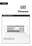
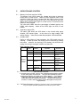
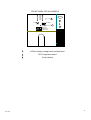
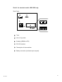
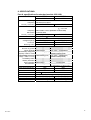
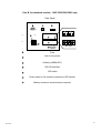
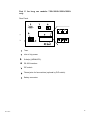
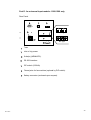
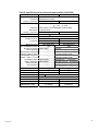
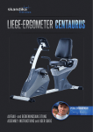
UPS + AVR
Uninterruptible Power System
User’s Manual
Line-Interactive Sine Wave
(Standard models: 650/1000/1200/1500/2000/3000)
(Long run models: 750/1000/1500/2000)
(Universal input models: 1000/1500)
100%
80%
60%
40%
20%
- -
LOAD
+
-
BATTERY
NORMAL
BACK UP
LOW BATT.
OVER LOAD
10%
D10-1000A
1
TABLE OF CONTENTS
Part A. for Standard models: 650/1000 only -------------------------- Page 3
1.
INTRODUCTION
1.1 Overview
1.2 Battery replacement warning
1.3 Communication interface
Part B. for standard models:1200/1500/2000/3000 only ----------- Page 4
1.
INTRODUCTION
1.1 Overview
1.2 Battery replacement warning
1.3 DIP switches
1.4 Communication interface
Part C. for long run models:750L/1000L/1500L/2000L only ------- Page 5
1.
INTRODUCTION
1.1 Overview
1.2 Battery replacement warning
1.3 DIP switches
1.4 Communication interface
Part D. for universal input models:1000/1500 only ------------------ Page 6
1.
INTRODUCTION
1.1 Overview
1.2 Battery replacement warning
1.3 DIP switches
1.4 Communication interface
FOR ALL MODELS
2.
MAIN FEATURES ---------------------------------------------------- Page 7
3.
CAUTION --------------------------------------------------------------- Page 7
4.
INSTALLATION AND OPERATION ----------------------------- Page 7 – 8
4.1 Installation
4.2 Operation
4.3 Connecting the FAX machine
5.
INDICATION AND CONTROL ------------------------------------ Page 9 – 10
5.1 Battery level and load level LEDs
5.2 Operation status LED
5.3 Audible alarm
5.4 Auto self-test function
5.5 DIP switch settings
5.6 Remote control
5.7 Reset the UPS
6.
COMMUNICATION INTERFACE -------------------------------- Page 11
6.1 The definition and setup for RS-232
6.2 The definition and setup for DB9 (optional)
7.
TROUBLE SHOOTING --------------------------------------------- Page 12
8.
SPECIFICATIONS --------------------------------------------------- Page 13 – 21
9.
IMPORTANT SAFETY INSTRUCTIONS ---------------------- Page 23
D10-1000A
2
1.
INTRODUCTION (for standard models: 650/1000 only)
1.1 Overview:
The series UPS is an advanced Line-Interactive Uninterruptible
Power System which produces pure sine wave power to your
equipment; unlike the traditional off-line UPS, the series provide very
short transference when blackouts happen, and zero transference
from AC mode to battery mode or from battery mode to AC mode.
The voltage regulation performance of series is similar to an On-line
UPS; however, the series provide efficiency over 98% under normal
power condition. Two charge modes, quick charge and trickle
charge, are provided to maintain the batteries in the best condition.
1.2 Battery replacement warning
The self-test function (by pushing the button) will inform you with
an alarm when the batteries are weak and require replacement.
1.3 Communication interface
A communication interface port for sensing input voltage, output
voltage, battery capacity, output power level, and UPS statuses are
provided; through this port, you can remote control the UPS for
turning on and off by customized schedule and setting the auto-test
procedure.
D10-1000A
3
1.
INTRODUCTION (for standard models: 1200/1500/2000/3000 only)
1.1 Overview:
The series UPS is an advanced Line-Interactive Uninterruptible
Power System which produces pure sine wave power to your
equipment; unlike the traditional off-line UPS, the series provide very
short transference when blackouts happen, and zero transference
from AC mode to battery mode or from battery mode to AC mode.
The voltage regulation performance of series is similar to an On-line
UPS; however, the series provide efficiency over 98% under normal
power condition. Two charge modes, quick charge and trickle
charge, are provided to maintain the batteries in the best condition.
1.2 Battery replacement warning
The self-test function (by pushing the button) will inform you
with an alarm when the batteries are weak and require
replacement.
1.3 DIP Switches
DIP switches allow you to adjust the UPS for different line
voltages and frequencies in different areas. It also allows you
to enable the green power function to shut down the UPS
automatically if the load is less than 25W, and then to extend
the battery life.
1.4 Communication interface
A communication interface port for sensing input voltage, output
voltage, battery capacity, output power level, and UPS statuses are
provided; through this port, you can remote control the UPS for
turning on and off by customized schedule and setting the auto-test
procedure.
D10-1000A
4
1.
INTRODUCTION (for long run models: 750L/1000L/1500L/2000L
only)
1.1
Overview:
The series UPS is an advanced Line-Interactive Uninterruptible
Power System which produces pure sine wave power to your
equipment; unlike the traditional off-line UPS, the series provide
very short transference when blackouts happen, and zero
transference from AC mode to battery mode or from battery
mode to AC mode. The voltage regulation performance of the
series is similar to an On-line UPS; however, the series provide
efficiency over 98% under normal power condition. Two charge
modes, quick charge and trickle charge, are provided to maintain
the batteries in the best condition.
1.2
Battery replacement warning
The self-test function (by pushing the button) will inform you
with an alarm when the batteries are weak and require
replacement.
1.3
DIP switches
DIP switches allow you to adjust the UPS for different line voltages
and frequencies in different areas. It also allows you to enable the
green power function to shut down the UPS automatically if the
load is less than 25W, and then to extend the battery life.
1.4
Communication interface
A communication interface port for sensing input voltage, output
voltage, battery capacity, output power level, and UPS statuses are
provided; through this port, you can remote control the UPS for
turning on and off by customized schedule and setting the auto-test
procedure.
D10-1000A
5
1.
INTRODUCTION (for universal input models: 1000/1500 only)
1.1 Overview:
The series UPS is an advanced Line-Interactive Uninterruptible
Power System which not only produces pure sine wave power, but
also provide universal input range to your equipment; unlike the
traditional off-line UPS, the series provide very short transference
when blackouts happen, and zero transference from AC mode to
battery mode or from battery mode to AC mode. The voltage
regulation performance of the series is similar to an On-line UPS;
however, the series provide efficiency over 95% under normal
power condition. Two charge modes, quick charge and trickle
charge, are provided to maintain the batteries in the best condition.
The series is made with Universal input, but single output
110V or so.
1.2 Battery replacement warning
The self-test function (by pushing the button) will inform you with
an alarm when the batteries are weak and require replacement.
1.3 DIP switches (Available for 1500VA)
DIP switches allow you to adjust the UPS for different line voltages and
frequencies in different areas. It also allows you to enable the green
power function to shut down the UPS automatically if the load is less
than 25W, and then to extend the battery life.
1.4 Communication interface
A communication interface port for sensing input voltage, output voltage,
battery capacity, output power level, and UPS statuses are provided;
through this port, you can remote control the UPS for turning on and off by
customized schedule and setting the auto-test procedure.
D10-1000A
6
FOR ALL MODELS
2.
MAIN FEATURES :
*
Line-Interactive structure.
*
Microprocessor based design.
*
‘Green Power’ design with auto on/off function.
*
RS-232 interface for communication.
*
Protection for overload, short circuit, & over heat.
*
Pure sine wave output.
*
Zero Transference.
3.
CAUTION:
*
The UPS is designed to power computer loads and the associated
peripheral devices, such as monitors, modems, external H-Disk
drivers, etc. To ensure the performance of the UPS, Do Not load
the UPS with laser printer, motor, or any type of inductive load.
*
Connecting the UPS to a two-pole, three-wire grounding mains
receptacle. Connection with any other type of receptacle may
result in a shock hazard and may violate local electrical codes.
*
Do not allow water or any foreign object to get inside the UPS.
And do not put objects containing liquid on or near the unit.
*
Keep UPS away from fire or heating sources.
*
The standard models of 650/1000/1200/1500/2000/3000 are shipped
from the factory with fully charged internal batteries; however,
the batteries may lose some energy during delivery and storage.
To ensure that the UPS will provide the expected run-time during
a blackout, the UPS must be left in charging for at least 5 hours
before your first use. The batteries are charged automatically
by the UPS whenever the UPS is connected with city power (No
need to turn on the UPS).
4.
INSTALLATION & OPERATION:
4.1 Installation
D10-1000A
*
Inspecting the packing carton for damage that may have occurred
while in transit. Immediately notify the carrier and place of purchase
if any damage is found. Retain the package for future use.
*
Plugging the power cord to a 3-wire grounding receptacle. If an
extension cord must be used between the UPS and the nearest
wall outlet, use a 3-wire grounding type rated for at least 20 Amps.
7
*
4.2
Connecting your equipment to the UPS. To ensure that your
computer equipment will be protected during a utility failure, it is
important to make sure that the maximum power need from the
equipment is not over the rated capacity of the UPS. Red LED will
lighted up and alarm will beep if the load is over the rated value.
Meantime, if the overload is severe, the UPS will shut down
immediately for protecting UPS itself.
Operation
4.2.1 After installation with normal city power, the UPS will charge the
battery automatically, and the status LED blinks green every 2
seconds. Please push the button about one second on the front
panel, then the UPS will give power to the outlets after a short-time of
self-test.
4.2.2 Pushing the button for 4 seconds, the UPS will turn off the power on the
outlets. But, the UPS will keep charging if city power is normal. To
stop the charging, please pull out the power cord to shut down the UPS
completely.
4.2.3 During a blackout, push the button for entering idle mode (Ref.
Indication Table), then push again for one second, and the UPS will be
turned on and enter into backup mode. To turn off the power from
UPS; please push the button for 4 seconds, then UPS’s status LED will
blink orange every 2 seconds, wait for 5 seconds, and UPS will turn off
the power automatically.
4.2.4 In idle mode, UPS will turn off the power automatically within 12
seconds during a utility failure; while UPS will keep charging the
batteries if the utility power is normal. When utility power is
normal, please pull out the power cord if you want to turn off the
UPS completely.
4.2.5 When “Green Power” function is enabled, the UPS will turn off the
power within 30 seconds after blackout occurs with the power
consumption lower than 25W.
4.3
D10-1000A
Connecting the FAX machine:
When you are connecting a FAX machine or modem with the UPS,
please also connect the phone line through the UPS. The UPS
may offer protection against damaging power fluctuations and
surges that travel through the phone line. The UPS also offers a
ring on function when the power is off. UPS power will be turned
on automatically when a ringing signal exists in the phone line, and
the UPS will keep power on until the FAX machine finishes receiving
work, then the UPS will be turned-off by the green power function.
In a long-time black-out situation, you won’t miss any FAX data by
this function.
8
5.
INDICATION AND CONTROL
5.1
Battery level and load level LEDs
The battery level LEDs show the voltage level both in back-up
mode and in normal mode. When the LED indicates 20% of the
capacity in back-up mode, it means that the UPS is going to shut
down; for the length of backup time left, it will depend on the load.
While when all five LEDs light in normal mode, it means that the
battery is fully charged.
The load level LEDs show the percentage of added load by the
UPS’s rated capacity. When all five LEDs light, the UPS is over
loaded.
5.2
Operation status LED
The status LED shows the UPS status, in the normal utility power
duration, LED shows Green. In the event of a utility outage, LED
shows Orange. If the UPS is under fault operation, LED shows Red.
5.3
Audible alarm
During a utility failure or fault operation, the UPS emits beep for
warning. In back-up mode, the beeping can be silenced by pushing
the button. However, the warning of low battery will still sound for
urging user to leave computer without any data loss.
Basic Indication Table:
LED
ALARM
PERIOD
Idle mode Green
No Beep
One flash every 2 sec.
Utility Good
Orange
No Beep
One flash every 2 sec.
Utility outage
Red
No Beep
One flash every 2 sec.
Timer on, refer to
Item 5.6
Green
No Beep
Continuously
Normal
(Utility good)
Orange
Yes, can be One beep every 4 sec.
silenced
2 beeps every 4 sec.
Orange
No, can Not 4 beeps per sec.
be silenced
Red
Yes
Normal/
Back-up
mode
D10-1000A
8 beeps per sec.
STATUS
Back-up
(No load)
Back-up
(Loading)
Battery Low
Battery NG.
5.4
Auto self-test Function:
In normal mode of UPS, turn on your computer and push the button
on the front panel for self-test. The UPS will simulate a power
outage and transfer your load to the UPS’s battery. If low battery
warning sounds during the test, it means that the battery set is
weak and requires extended recharge. If battery NG warning
sounds, it means that the battery set is damaged and requires
replacement.
5.5
DIP Switch Settings (Available for standard models: 1200/1500/2000/3000,
long run models: 750/1000/1500/2000 & universal input model: 1500)
9
DIP Switch
1
2
3
4
Function Table of DIP Switch
Switch No.
Function
Voltage = 100V / 200V
Voltage = 110V / 220V
Voltage = 115V / 230V
Voltage = 120V / 240V
Frequency for DC Start ※
1
Up
2
Down
V
V
V
V
Up
V
V
3
Down
Up
4
Down
Up
Down
V
V
50Hz 60Hz
Green Power
Yes
(Enable/Disable)
※ Frequency for DC start is not available for universal input series.
No
P.S.: Program setting active only after the UPS is re-started.
D10-1000A
5.6
Remote Control:
The UPS can be set for daily shutdown/wake up. This command must
be set through the RS-232 interface. When this function is set, the
timer inside the UPS will begin to run, and the load will be turned off by
the shutdown/wake up schedule. During the period of turn off to the
next turn on, the status LED blinks red every 2 seconds. .
5.7
Reset the UPS
If any abnormal condition occurs, and the item 4.2.1 ~ 4.2.4 can not
be executed, please push the button for at least 10 sec. until the
status LED becomes orange, then the UPS is reset.
10
6.
COMMUNICATION INTERFACE:
The UPS provides both computer interfaces, smart software
(RS-232) and dry contact (DB-9); by using different software
and cable, the UPS shows different monitoring function.
6.1 The definition and setup for RS-232 is as following:
Baud Rate
: 2400 dps
Data Length : 8 bits
Stop Bit
: 1 bit
Parity
: None
5 4 3 2 1
9 8 7 6
Pin #6 : RS-232 data Tx out.
Pin #7 : Common of Pin #6 and Pin #9
Pin #9 : RS-232 data Rx In
6.2 The definition and setup for DB9 (optional) is as following:
Pin #2 : AC Power Failure
Pin #4 : Common GND of Pin #2 & Pin #5
Pin #5 : UPS Battery Low
Pin #6 : Turn off UPS
Pin #7 : GND of Pin6
The interface with computer is diagramed as above for your reference.
Use Pin #4 as the common of Pin #2 and Pin #5, Pin #2 and Pin #4 will
become close loop from open when the utility fails, Pin #5 and Pin #4 will
become close loop from open when the battery level is low.
The UPS will shut down itself when the high level from RS-232,
sustained for 3 seconds, which is applied between Pin #6 and Pin #7.
D10-1000A
11
7. TROUBLE SHOOTING
Problem
Possible Cause
UPS no reaction while AC 1. Line cord plug is loose
is connected
2. Fuse on rear panel blown
(Inside the drawer of inlet)
3. Dead wall socket
Action to Take
1. Check the line cord plug
2. Replace fuse
3. Check wall socket with a
table lamp.
Power output is normal, UPS UPS is over loaded
emits continuous beep,
status LED shows RED.
Turn off UPS and unplug
excessive loads from UPS.
UPS emits continuous beep, UPS has shut down due to
status LED show RED, & no overload.
power on outlets.
Unplug excessive loads from
UPS, press button to reset the
buzzer, and turn on the UPS
again.
UPS does not provide
expected run time
1. Excessive loads connected
at UPS’s outlets.
2. Battery is weak and can not
provide enough capacity.
Do not operate the UPS, and
leave the UPS plugged in for
10 hours. Then, test it again,
if UPS still can not provide
expected run time, battery
should be replaced.
Button on front panel
doesn’t work
1. The CPU inside UPS is not
running correctly.
2. Button damaged.
1.Push the button for 10
seconds to reset the UPS.
2. Unplug line cord and all
loads from the UPS to let it
shut down automatically,
and call for service.
Battery is weak and should be Replace batteries.
To push button for testing
under AC mode, UPS emits replaced
urgent beep (8 beeps per
sec.) and RED LED blinks at
the same time.
UPS can not be turned on. 1. Battery polarity wrong
2. UPS fault
D10-1000A
1. Check battery connection.
2. Call for service.
12
FRONT PANEL FOR ALL MODELS
100%
80%
60%
40%
20%
1
3
- -
LOAD
+
-
BATTERY
2
NORMAL
BACK UP
LOW BATT.
OVER LOAD
1
LEDs of battery voltage level and load level.
2
LED of operation status.
3
D10-1000A
Control button.
13
Part A. for standard models: 650/1000 only
Rear Panel
5
4
2
NEMA Type
3
1
0
0
+
00-
6
IEC Type
D10-1000A
1
Fuse.
2
Inlet of city power.
3
Outlet(s) (NEMA or IEC).
4
RS-232 Interface.
5
Phone jacks for fax machine.
6
Battery connector (enclosed upon request).
14
8. SPECIFICATIONS:
Part A. specifications for standard models: 650/1000:
CAPACITY
650VA
1000VA
390W
INPUT
Voltage
Frequency
Current (110V/220V)
OUTPUT
Voltage
600W
Selectable 100/110/115/120V 1ø or 200/220/230/240V 1ø
50Hz/60Hz Auto detect
6.5A / 3.25A
10A / 5A
100/110/115/120V 1ø or 200/220/230/240V 1ø ±3% for Back-up Mode
< ±10% for AVR
Frequency
Wave Form
Current (110V/220V)
TRANSFER TIME
BATTERY
Voltage/Capacity
Level Ind.
Recharge Time
LED / ALARM INDICATION
Normal city power
Back up Mode
Abnormal Freq. of City power
(Frequency > 65Hz or < 47Hz)
Abnormal Voltage of City power
(Voltage > 126% or < 77%)
Low Battery Alarm
Battery Fail Alarm
Over load Alarm
Thermal Alarm
50Hz or 60Hz ± 0.1Hz (Selectable under DC start)
True Sine Wave
5.8A / 2.9A
Transfer Time < 3 ms
Lead-Acid, maintenance free
12V 9Ah X 1pcs
YES
9.1A / 4.6A
12V 7Ah X 2pcs
YES
90% within 8 hrs
90% within 5 hrs
LED
Alarm
GRN Lighting
No beep
ORG Flashing
B-B-----B-B----- (2 beeps/4sec.)
ORG Flashing (quick) B-B-----B-B----- (2 beeps/4sec.)
(Transfer to backup mode)
ORG Flashing (slow) B-B-----B-B----- (2beeps/4sec.)
(Transfer to backup mode)
ORG Flashing
B-B-B-B-B-B-------- (4 beeps/sec.)
RED Flashing
B.B.B.B.B.B.B.B.
.(8 beeps/sec.)
RED Lighting
B……….. (Continuously)
RED Flashing
G..... R.....
(G = 16beeps/2sec. R = silence / 2sec.)
LOAD LEVEL INDICATION
DC START / ALARM RESET
RS-232 INTERFACE
ENVIRONMENT TEMP.
ENVIRONMENT HUMIDITY
DIMENSIONS (L x H x W)
SHIPPING DIM. (L x H x W)
WEIGHT (N.W. / G.W.)
D10-1000A
YES
YES
YES
YES
YES
YES
0 - 37 ℃
30-95% Non-Condensing
38 x 20 x 18 (cm)
48 x 33 x 30 (cm)
11 / 12 kgs
38 x 20 x 18 (cm)
48 x 33 x 30 (cm)
15 / 16 kgs
15
Part B. for standard models: 1200/1500/2000/3000 only
Rear Panel
4
5
6
2
NEMA Type
3
3
1
0
0
D10-1000A
+
00-
7
IEC Type
1
Fuse.
2
Inlet of city power.
3
Outlet(s) (NEMA/IEC).
4
RS-232 Interface.
5
DIP switch
6
Phone jacks for fax machine (optional by DIP switch).
7
Battery connector (enclosed upon request).
16
Part B. specifications for standard models: 1200/1500/2000/3000:
CAPACITY
INPUT
1200VA
720W
1500VA
900W
2000VA
1200W
3000VA
1800W
Voltage
Frequency
Current (110V/220V)
OUTPUT
Voltage
Selectable 100/110/115/120V 1ø or 200/220/230/240V 1ø
50Hz/60Hz Auto detect
12A / 6.3A
16A / 8A
20A / 10A
30A / 15A
Frequency
Wave Form
Current (110V/220V)
TRANSFER TIME
50Hz or 60Hz ± 0.1Hz (Selectable under DC start)
True Sine Wave
11A / 5.5A
13.6A / 6.8A 18.2A / 9.1A 27.2A / 13.6A
Transfer Time < 3 ms
100/110/115/120V 1ø or 200/220/230/240V 1ø ±3% for Back-up Mode
< ±10% for AVR
BATTERY
Lead-Acid, maintenance free
Voltage/Capacity 12V 7Ah X 3pcs 12V 7Ah X 3pcs 12V 7Ah X 4pcs 12V 7Ah X 6pcs
Level Ind.
YES
YES
YES
YES
Recharge Time
90% within 2 hrs
LED / ALARM INDICATION
LED
Alarm
Normal city power GRN Lighting
No beep
Back up Mode ORG Flashing
B-B-----B-B----- (2 beeps/4sec.)
Abnormal Freq. of City power ORG Flashing (quick)
B-B-----B-B----- (2 beeps/4sec.)
(Frequency > 65Hz or < 47Hz)
(Transfer to backup mode)
Abnormal Voltage of City power ORG Flashing (slow)
B-B-----B-B----- (2beeps/4sec.)
(Transfer to backup mode)
(Voltage > 126% or < 77%)
Low Battery Alarm ORG Flashing
B-B-B-B-B-B-------- (4 beeps/sec.)
Battery Fail Alarm RED Flashing
B.B.B.B.B.B.B.B.
.(8 beeps/sec.)
Over load Alarm RED Lighting
B……….. (Continuously)
Thermal Alarm RED Flashing
G..... R.....
(G = 16beeps/2sec. R = silence / 2sec.)
YES
YES
DC START / ALARM RESET
YES
YES
RS-232 INTERFACE
YES
YES
ENVIRONMENT TEMP.
0 - 37 ℃
ENVIRONMENT HUMIDITY 30-95% Non-Condensing
LOAD LEVEL INDICATION
YES
YES
YES
DIMENSIONS (L x H x W)
45 x 20 x 18 (cm) 45 x 20 x 18 (cm) 51 x 20 x 18 (cm) 51 x 20 x 18 (cm)
SHIPPING DIM. (L x H x W)
54 x 33 x 30 (cm) 54 x 33 x 30 (cm) 61 x 33 x 30 (cm) 61 x 33 x 30 (cm)
WEIGHT (N.W. / G.W.)
D10-1000A
YES
YES
YES
19.5/20.5 kgs
21/22 kgs
25/26 kgs
36/37 kgs
17
Part C. for long run models: 750L/1000L/1500L/2000L
only
Rear Panel
4
5
6
2
NEMA Type
3
3
1
0
0
1
Fuse.
2
Inlet of city power.
+
00-
IEC Type
Outlet(s) (NEMA/IEC).
3
4
RS-232 Interface.
5
DIP switch
6
7
D10-1000A
7
Phone jacks for fax machine (optional by DIP switch).
Battery connector.
18
Part C. specifications for long run models 750/1000/1500/2000:
CAPACITY
750VA
1000VA
1500VA
2000VA
Continuous Loading
500W
700W
900W
1200W
Max. Loading
750W
1000W
1500W
2000W
(< 30sec.)
(< 30 sec.)
(< 30 sec.)
(< 30 sec.)
INPUT
Voltage
Frequency
Current (110V/220V)
OUTPUT
Voltage
Frequency
Wave Form
Current (110V/220V)
TRANSFER TIME
BATTERY
Voltage
Selectable 100/110/115/120V 1ø or 200/220/230/240V 1ø
50Hz/60Hz Auto detect
8A / 4A
10A / 5A
16A / 8A
20A / 10A
100/110/115/120V 1ø or 200/220/230/240V 1ø ±3% for Back-up Mode
< ±10% for AVR
50Hz or 60Hz ± 0.1Hz (Selectable under DC start)
True Sine Wave
6.8A / 3.4A
9.1A / 4.6A
Transfer Time < 3 ms
36V
48V
24V (optional) 36V (optional)
13.6A / 6.8A
18.2A / 9.1A
48V
72V
Level Ind.
YES
YES
YSE
YSE
Protection for reverse
YES
YES
YES
YES
battery polarity
CHARGE
Voltage 40.95V / 27.3V 54.60V / 40.95V
54.60V
81.90V
Maximum Current
6A
6A
6A
6A
LED / ALARM INDICATION
LED
Alarm
Normal city power GRN Lighting
No beep
Back up Mode ORG Flashing
B-B-----B-B----- (2 beeps/4sec.)
Abnormal Freq. of City power ORG Flashing (quick) B-B-----B-B----- (2 beeps/4sec.)
(Frequency > 65Hz or < 47Hz)
(Transfer to backup mode)
Abnormal Voltage of City power ORG Flashing (slow) B-B-----B-B----- (2beeps/4sec.)
(Voltage > 126% or < 77%)
(Transfer to backup mode)
Low Battery Alarm ORG Flashing
B-B-B-B-B-B-------- (4 beeps/sec.)
Battery Fail Alarm RED Flashing
B.B.B.B.B.B.B.B.
.(8 beeps/sec.)
Over load Alarm RED Lighting
B……….. (continuously)
Thermal Alarm RED Flashing
G..... R.....
(G = 16beeps/2sec. R = silence / 2sec.)
LOAD LEVEL INDICATION
YES
YES
YES
YES
DC START / ALARM RESET
YES
YES
YES
YES
RS-232 INTERFACE
YES
YES
YES
YES
ENVIRONMENT TEMP.
0 - 37 ℃
ENVIRONMENT HUMIDITY 30-95% Non-Condensing
DIMENSIONS (L x H x W)
45 x 20 x 18 (cm) 45 x 20 x 18 (cm) 45 x 20 x 18 (cm) 45 x 20 x 18 (cm)
SHIPPING DIM. (L x H x W)
54 x 33 x 30 (cm) 54 x 33 x 30 (cm) 54 x 33 x 30 (cm) 54 x 33 x 30 (cm)
WEIGHT (N.W. / G.W.)
13.0/14.0 kgs 14.5/15.5 kgs 17.5/18.5 kgs 17.5/18.5 kgs
D10-1000A
19
Part D. for universal input models: 1000/1500 only
Rear Panel
4
5
6
2
NEMA Type
3
3
1
0
0
1
Fuse.
2
Inlet of city power.
3
D10-1000A
+
00-
7
IEC Type
Outlet(s) (NEMA/IEC).
4
RS-232 Interface.
5
DIP switch (1500VA)
6
Phone jacks for fax machine (optional by DIP switch).
7
Battery connector (enclosed upon request).
20
Part D. specifications for universal input models 1000/1500:
CAPACITY
1000VA (600W)
INPUT
Voltage
Frequency
Current (110V/220V)
OUTPUT
Voltage
Frequency
Wave Form
Current (110V/220V)
TRANSFER TIME
BATTERY
Voltage/Capacity
Level Ind.
Recharge Time
LED / ALARM INDICATION
Normal city power
Back up Mode
Abnormal Freq. of City power
(Frequency > 65Hz or < 47Hz)
Abnormal Voltage of City power
(Voltage > 126% or < 77%)
Low Battery Alarm
Battery Fail Alarm
Over load Alarm
Thermal Alarm
1500VA (900W)
100/110/115/120V 1ø or 200/220/230/240V 1ø Auto detect
50Hz/60Hz Auto detect
10A / 5A
100/110/115/120V 1ø ± 3%
16A / 8A
for Back-up Mode
< ±10% for AVR
50Hz or 60Hz ± 0.1Hz (Selectable under DC start)
True Sine Wave
9A / 4.5A
Transfer Time < 3 ms
13.6A / 6.8A
Lead-Acid, maintenance free
12V 7Ah X2pcs
12V 7Ah X 3pcs
YES
YES
90% within 5 hrs
90% within 2 hrs
LED
Alarm
GRN Lighting
No beep
ORG Flashing
B-B-----B-B----- (2 beeps/4sec.)
ORG Flashing (quick)
B-B-----B-B----- (2 beeps/4sec.)
(Transfer to backup mode)
ORG Flashing (slow)
B-B-----B-B----- (2beeps/4sec.)
(Transfer to backup mode)
ORG Flashing
B-B-B-B-B-B-------- (4 beeps/sec.)
RED Flashing
B.B.B.B.B.B.B.B.
.(8 beeps/sec.)
RED Lighting
B……….. (Continuously)
RED Flashing
G..... R.....
(G = 16beeps/2sec. R = silence / 2sec.)
LOAD LEVEL INDICATION
DC START / ALARM RESET
RS-232 INTERFACE
OPERATION TEMP.
OPERATION HUMIDITY
DIMENSIONS (L x H x W)
SHIPPING DIM. (L x H x W)
WEIGHT (N.W. / G.W.)
D10-1000A
YES
YES
YES
YES
YES
YES
0 - 37 ℃
30-95% Non-Condensing
38 x 20 x 18 (cm)
48 x 33 x 30 (cm)
17/18kgs
45x 20 x 18 (cm)
54x 33 x 30 (cm)
22/23kgs
21
9.
IMPORTANT SAFETY INSTRUCTIONS
●
When replacing the batteries, use the same number and the same
type of batteries.
●
Do not dispose of batteries in a fire; the battery may explode.
●
Do not open or mutilate the battery or batteries, released
electrolyte is harmful to the skin and eyes.
●
A battery can present a risk of electric shock and high short circuit
current. The following precaution should be observed when
working on batteries.
* Remove watches, rings or other metal objects.
* Use tools with insulated handles.
D10-1000A
●
To prevent an overbalance of this unit, with the installation the
additional stabilizer are to mount at the bottom side.
●
This unit should be installed from service personnel.
●
The equipment can be operated by any individuals with no previous
experience.
●
“The socket-outlet shall be installed near the equipment and easily
accessible.”
●
“With the installation of this equipment it should be prevented, that
the sum of the leakage current of the UPS an the connected
consumer does not exceed 3.5mA.”
●
Attention, hazardous through electric shock. Also with
disconnection of this unit from the main, hazardous voltage still
may be accessible through supply from battery.
●
The battery supply should be therefore disconnected in the plus
and minus pole through the from the outer enclosure accessible
battery fuses when maintenance or service work inside the UPS is
considered.
●
The lead acid battery may cause chemical hazard.
●
The battery presents a risk of electric shock and energy hazard.
●
Batteries will be disposed by the manufacturer or importer.
Customers need to send them back with no charge for disposal.
●
Electrical hazard, the discharge time is about 5 min.
22


![Manual[DOWNLOAD]](http://vs1.manualzilla.com/store/data/005715994_1-2fafd5cf8faf458a6c3437b6894f1203-150x150.png)