1
WLM-3501
Wireless ADSL2+ Modem Router
User Manual
Version: 1.0
Table of Contents
INTRODUCTION....................................................................................... 4
1
KEY FEATURES................................................................................. 5
2
PACKAGE CONTENTS ....................................................................... 6
3
CAUTIONS ....................................................................................... 7
4
PRODUCT LAYOUT ........................................................................... 8
BACK LABEL
9
5
SYSTEM REQUIREMENTS ............................................................... 10
6
WLM-3501 PLACEMENT ................................................................. 10
7
SETUP LAN, WAN ........................................................................... 10
8
PC NETWORK ADAPTER SETUP ...................................................... 11
WINDOWS XP
11
WINDOWS VISTA/WINDOWS 7 12
9
BRING UP THE WLM-3501 ............................................................. 14
10
INITIAL SETUP WLM-3501 ............................................................ 14
LOGIN PROCEDURE
14
STATUS ................................................................................................. 15
STATUS
STATISTICS
DHCP LIST
DIAGNOSTICS
15
16
17
18
11
CONFIGURATION WIZARD ............................................................ 19
12
BASIC SETTINGS ........................................................................... 20
LAN SETTINGS
DHCP SETTINGS
WAN SETTINGS
SECURITY SETTINGS
WIRELESS ACL
13
ADVANCED SETTINGS .................................................................... 30
ADVANCES WIRELESS
QOS
UPNP
ROUTING
SNMP
DDNS
NAT
TR-69
14
20
21
22
27
29
30
32
34
35
36
37
38
39
FIREWALL SETTINGS ..................................................................... 40
FIREWALL
40
ACL
IP FILTER
DMZ
VIRTUAL SERVER
15
41
42
45
46
TOOLBOX SETTINGS ...................................................................... 47
PASSWORD
TIME SETTINGS
FIRMWARE UPGRADE
REBOOT
47
53
54
55
Revision 1.0
© Sitecom Europe BV 2011
Note: All the information contained in this manual was correct at the time of
publication.
However, as our engineers are always updating and improving the product, your
device’s software may have a slightly different appearance or modified
functionality than presented in this manual.
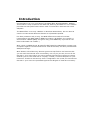
Introduction
Congratulations on your purchase of the WLM-3501 Wireless ADSL2+ Modem.
This modem is fully compliant with 802.11b, 802.11g and 802.11n. This modem
provides the best performance when used in combination with 802.11n client
adapters.
The WLM-3501 is not only a Modem or Wireless Access Point, but can also be
used to connect wired Ethernet devices at 10/100 Mbit speeds.
For data protection and privacy, the WLM-3501 can encode all wireless
transmissions with WEP, WPA or WPA2 encryption. By default, the modem is
secured with a WPA2 (AES) encryption key. (The WPA2-key is printed on the
label underneath the modem.)
With a built-in DHCP Server & powerful SPI firewall the WLM-3501 protects your
computers against intruders and known Internet attacks, and also provides safe
VPN pass-through.
With Sitecom Cloud Security, Sitecom goes one step further and ensures that
you can surf the Internet even more safely, not only on your PC, but on all the
devices in your home which you use to access the Internet. It does not matter
whether you surf the Internet on a laptop, a tablet, a mobile telephone or your
television. Thanks to the security that is integrated in the router, all the Internet
devices in your home are protected against the dangers of Internet criminality.
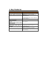
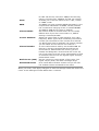
1 Key Features
Features
IEEE 802.11g compliant
Based on 802.11n technology
Four 10/100 Mbps Port
(Auto-Crossover)
Firewall supports Virtual
Server
Mapping, DMZ, IP Filter, ICMP
Blocking, SPI
Supports 802.11i
(WPA/WPA2, AES), VPN passthrough
Integrated modem (Annex A)
Sitecom Cloud Security
Advantages
Fully Interoperable with IEEE 802.11b /
IEEE802.11g compliant devices
WLM-3501: Up to 6 times faster than
regular 802.11g
(in combination with a 150n or 802.11n
wireless adapter)
To connect four wired PC's as well.
Avoids the attacks of Hackers or Viruses
from Internet
Provide mutual authentication (Client
and dynamic encryption keys to
enhance security)
Fully compatible with the fastest
ADSL2+ connections up-to-date.
Protect your home against cybercrime
while browsing.
2 Package Contents
Open the package carefully, and make sure that none of the items listed
below are missing. Do not discard the packing materials, in case of return;
the unit must be shipped back in its original package.
1.
WLM-3501 modem/router
2.
110V~240V 12V 1A Power Adapter
3.
Quick Install Guide
4.
CD (User’s Manual)
5.
Warranty card
6.
UTP cable
7.
RJ11 cable
3 Cautions
This router’s design and manufacturer has your safety in mind. In order to
safely and effectively use this router, please read the following before usage.
3.1 Usage Cautions
The user should not modify this router. The environmental temperature
should be within +5 ~ +35 degrees Celsius.
3.2 Power
The router’s power voltage is DC 12V 1A.
When using this router, please connect the supplied AC adapter or AC adapter
cable to the router’s power jack. When placing the adapter cable, make sure
it can not get damaged or be subject to pressure. To reduce the risk of
electric shock, unplug the adapter first before cleaning it. Never connect the
adapter to the router in a humid or dusty area. Do not replace the adapter or
cable’s wire or connector.
3.3 Repair
If the router has a problem, you should take it to an appointed repair centre
and let the specialists do the repair. Never repair the router yourself, you
might damage the router or endanger yourself.
3.4 Disposing of the Router
When you dispose of the router, be sure to dispose it appropriately. Some
countries may regulate disposal of an electrical device, please consult with
your local authority.
3.5 Others
When using this router, please do not let it come into contact with water or
other liquids. If water is accidentally spilled on the router, please use a dry
cloth to absorb the spillage. Electronic products are vulnerable, when using
please avoid shaking or hitting the router, and do not press the buttons too
hard.
- Do not let the router come into contact with water or other liquid.
- Do not disassemble the router, repair the router or change the design of the
router, any damage done will not be included in the repair policy.
- Avoid hitting the router with a hard object, avoid shaking the router and
stay away from magnetic fields.
- If during electrostatic discharge or a strong electromagnetic field the
product will malfunction, unplug the power cable. The product will return to
normal performance the next time it is powered on.
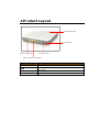
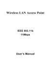
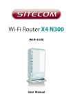
4 Product Layout
WPS/Reset button
Power button
Modem connection
Power connector
LAN / computer connections
Port
ADSL
LAN
Power connector
Power button
Description
Connect your telephone/ADSL cable this port
Connect the cable from your PC or network device to
this ports.
Connect your power adapter to this port.
Turn the modem On or Off.
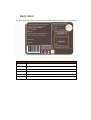
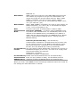
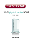
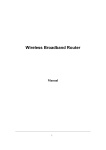
Back label
The back label describes the corresponding LED indications and port functionality.
LED
Description
Power
Lights up when powered ON. Blinks on TEST/RESET
ADSL
Lights up when an ADSL cable is connected.
Internet
Lights up when internet connection is UP.
WLAN
Lights up in Blue when WLAN is enabled. Blinks on traffic
OPS
Blinks when OPS mode is on
LAN1~4
When a LAN cable is connected the corresponding light lights up.
5 System Requirements
To begin using the WLM-3501, make sure you meet the following as minimum
requirements:
•
PC/Notebook.
•
1 Free Ethernet port.
•
Wi-Fi card/USB dongle (802.11 b/g/n) – optional.
•
Annex A, ADSL internet connection.
•
PC with a Web-Browser (Internet Explorer, Safari, Firefox, Opera)
•
Ethernet compatible CAT5 cables.
6 WLM-3501 Placement
You can place the WLM-3501 on a desk or other flat surface, or you can
mount it on a wall. For optimal performance, place your Wireless Broadband
Modem/Router in the center of your office (or your home) in a location that is
away from any potential source of interference, such as a metal wall or
microwave oven. This location must be close to a power connection and the
ADSL/phone line should not be over 2 meters long.
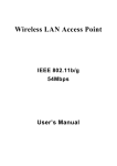
7 Setup LAN, WAN
Modem connection
LAN / computer connections
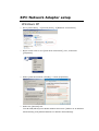
8 PC Network Adapter setup
Windows XP
•
Go to [Start Menu], [Control panel], [Network Connections].
•
Right-mouse-click on the [Local Area Connection]) icon, and select
[properties]
•
Select [Internet Protocol (TCP/IP)] =>Click [Properties].
•
Select the [General] tab.
The WL-358/359 supports DHCP. Please select both [Obtain an IP address
automatically] and [Obtain DNS server address automatically].
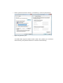
Windows Vista/Windows 7
•
Go to [Start Menu], [Control panel], [View network status and
tasks], -> [Manage network connections].
•
Right-mouse-click on the [Local Area Connection]) icon, and select
[properties]
•
Select [Internet Protocol Version 4 (TCP/IPv4)], and Click [Properties].
•
Open the [General] tab.
The WLM-3501 supports DHCP. Please select both [Obtain an IP address
automatically] and [Obtain DNS server address automatically].
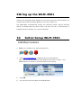
9 Bring up the WLM-3501
Connect the supplied power-adapter to the power inlet port and connect it to
a wall outlet. Press the Power-Button to turn the modem on.
The WLM-3501 automatically enters the self-test phase. During self-test
phase, the Power LED will blink briefly, and then will be lit continuously to
indicate that this product is in normal operation.
10
Initial Setup WLM-3501
LOGIN procedure
1. OPEN your browser (e.g. Internet Explorer).
4
Type http://192.168.0.1 in address bar and press [Enter]
Type user name and password (The default username is “admin”, the
password can be found on the back label of the device).
5
Click OK.
6
You will see the home page of the WLM-3501.
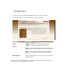
Status
The pages in the status section provide you general information about the
operational status of your device.
Status
The System status section allows you to monitor the current status of your
modem/router: the UP time, hardware information, serial number as well as
firmware version information is displayed here. The page also shows extensive
information concerning the ADSL status and current settings.
Statistics
You can view statistics on the processing of IP packets on the networking
interfaces. You will not typically need to view this data, but you may find it
helpful when working with your ISP to diagnose network and Internet data
transmission problems. To display statistics for any new data, click “Refresh”.
DHCP List
This page shows all DHCP clients (LAN PCs) currently connected to your
network. The table shows the assigned IP address, MAC address and expiration
time for each DHCP leased client.
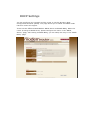
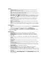
Diagnostics
The Diagnostics page allows you to test the current configuration.
Click ‘Start’ to let the modem router perform several tasks to verify if the
connection is operational.
11 Configuration Wizard
Click Wizard to configure the modem. The Setup wizard will now be displayed;
check that the adsl line is connected and click Next.
Select your country from the Country list. Select your internet provider. Click
Next.
Depending on the chosen provider, you may need to enter your user name and
password or hostname in the following window. After you have entered the
correct information, click Next.
Click Finish to complete the configuration.
12 Basic Settings
LAN Settings
This page is used to configure the LAN interface of your ADSL Router. You can
set IP address, subnet mask, and IGMP Snooping or modify the IPv6 address
range .
DHCP Settings
You can configure your network and the router to use the Dynamic Host
Configuration Protocol (DHCP). This page allows you to select the DHCP mode
that this router will support.
There are two different DHCP Modes: DHCP Server and DHCP Relay. When the
router is acting as DHCP server, please configure the router in the “DHCP
Server” page; while acting as DHCP Relay, you can setup the relay in the “DHCP
Relay” page.
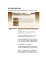
WAN Settings
This page allows you to manually configure the ADSL/WAN settings. The
settings on this page require some knowledge concerning the WAN configuration
we advice less-experienced users to configure the WAN settings using the
Wizard (Chapter 10)
ATM VC
• Virtual Circuit: VPI (Virtual Path Identifier) and VCI (Virtual Channel
Identifier) define a virtual circuit.
• VPI: The valid range for the VPI is 0 to 255. Enter the VPI assigned to
you. This field may already be configured.
• VCI: The valid range for the VCI is 32 to 65535. Enter the VCI assigned to
you. This field may already be configured.
• ATM QoS: Select CBR to specify fixed (always-on) bandwidth for voice or
data traffic. Select UBR for applications that are non-time sensitive, such
as e-mail. Select VBR for burst traffic and bandwidth sharing with other
applications.
• PCR: Divide the DSL line rate (bps) by 424 (the size of an ATM cell) to
find the Peak Cell Rate (PCR). This is the maximum rate at which the
sender can send cells.
• SCR: The Sustain Cell Rate (SCR) sets the average cell rate (long-term)
that can be transmitted.
• MBS: Maximum Burst Size (MBS) refers to the maximum number of cells
that can be sent at the peak rate. Type the MBS, which is less than 65535
Encapsulation:
• ISP: Select the encapsulation type your ISP uses from the Encapsulation
list.
Choices vary depending on what you select in the Mode field.
If you select Bridge in the Mode field, select 1483 Bridged IP.
If you select Routing in the Mode field, select PPPoA, 1483 Bridged IP, 1483
Router IP or PPPoE.
PPPoE/PPPoA
• User Name: Enter the user name exactly as your ISP assigned.
• Password: Enter the password associated with the user name above.
• Encapsulation: select Bridge in the Mode field, select either PPPoA or
RFC 1483.
• select Routing in the Mode field, select PPPoA, RFC 1483, ENET ENCAP or
PPPoE.
• Multiplex: Select the method of multiplexing used by your ISP. Choices are
VC or LLC.
• Connection: The schedule rule(s) have priority over your Connection
settings.
• Always on: Select Always on Connection when you want your connection
up all the time.
• Connect on Demand: Select Connect on Demand when you don't want
the connection up all the time and specify an idle time-out in the Max Idle
Timeout field
• Get IP Address: Choose Static or Dynamic
• Static IP Address: Enter the IP address of ADSL Router in dotted
decimal notation, for example, 192.168.1.254 (factory default).
• IP Subnet Mask: The default is 255.0.0.0. User can change it to other
such as 255.255.255.0.Type the subnet mask assigned to you by your ISP
(if given).
• Gateway: You must specify a gateway IP address (supplied by your ISP)
when you use 1483 Bridged IP in the Encapsulation field in the
previous screen.
•
•
•
•
Network Address Translation: Select None, Many to One or Many to
Many from the drop-sown list box. Refer to the NAT chapter for more
details.
RIP Version: Select the RIP version from RIP-1, RIP-2B and RIP-2M.
RIP Direction: Select the RIP direction from None, Both, In Only and Out
Only.
Multicast: IGMP (Internet Group Multicast Protocol) is a network-layer
protocol used to establish membership in a Multicast group - it is not used
to carry user data.
Wireless Settings
This section provides the wireless network settings for your router. You can
enable and configure the wireless AP function here.
Parameter
Band
Description
Please select the radio band from one of the following
options.
2.4GHz(B): 2.4GHz band, only allows 802.11b
wireless network client to connect this router
(maximum transfer rate 11Mbps).
2.4 GHz (G): 2.4GHz band, only allows 802.11g
wireless network client to connect this router
(maximum transfer rate 54Mbps).
2.4 GHz (B+G):2.4GHz band, only allows 802.11b
and 802.11g wireless network client to connect this
router (maximum transfer rate 11Mbps for 802.11b
clients, and maximum 54Mbps for 802.11g clients).
2.4 GHz (N): 2.4GHz band, only allows 802.11n
wireless network client to connect this router
(maximum transfer rate 150Mbps).
2.4 GHz (G+N):2.4GHz band, only allows 802.11g
and 802.11n wireless network client to connect this
router (maximum transfer rate 54Mbps for 802.11g
clients, and maximum 150Mbps for 802.11n clients).
2.4 GHz (B+G+N): 2.4GHz band, allows 802.11b,
802.11g, and 802.11n wireless network client to
connect this router (maximum transfer rate 11Mbps
Mode
SSID
Channel Width
Control Sideband
Channel Number
Radio Power (mW)
Associated Clients
for 802.11b clients, maximum 54Mbps for 802.11g
clients, and maximum 150Mbps for 802.11n clients).
It allows you to set the router to act in “AP”, “Client”
or “WDS” mode.
The SSID (up to 32 printable ASCII characters) is the
unique name identified in a WLAN. The ID prevents
the unintentional merging of two co-located WLANs.
The default SSID of the router is “default”.
Set channel width of wireless radio. Do not modify
default value if you don’t know what it is, default
setting is ‘Auto 20/40 MHz’.
Select the upper band or lower band for your radio
frequency. While upper band is selected, the channel
number you can select is from channel 5 to channel
11. While lower band is selected, the channel number
you can select is from channel 1 to channel 7.
It is the radio channel used by the wireless LAN. All
devices in the same wireless LAN should use the
same channel. Please select the country you are
located and designate a channel that the router will
use. If you want to let the router automatically to find
an available channel with the highest signal strength,
please select “Auto”.
Set the maximum output power of the router. The
higher output power, the wider coverage range.
Click “Show Active Clients” button and you can see
the wireless clients connected to the router.
When you finish, click ‘Apply Changes’ to save the settings made and restart the
router so the settings will take effect after it reboots.
Security Settings
This router provides complete wireless LAN security functions, include WEP, IEEE
802.1x, IEEE 802.1x with WEP, WPA with pre-shared key and WPA with RADIUS.
With these security functions, you can prevent your wireless LAN from illegal
access. Please make sure your wireless stations use the same security function.
Parameter
Encryption
Description
You can choose “None” to disable the encryption or select
“WEP”, “WPA(TKIP)”, “WPA2(AES)” or “WPA2 Mixed” mode for
security. When “WEP” is enabled, please click “Set WEP Key”
button to choose the default key and set the four sets of WEP
keys.
WEP –WEP is less level of security than WPA. WEP supports
64-bit and 128-bit key lengths to encrypt the wireless data.
WPA(TKIP) – WPA uses Temporal Key Integrity Protocol
(TKIP) for data encryption. TKIP utilized a stronger encryption
method and incorporates Message Integrity Code (MIC) to
provide protection against hackers.
WPA2(AES) – WPA2, also known as 802.11i, uses Advanced
Encryption Standard (AES) for data encryption. AES utilized a
symmetric 128-bit block data encryption.
Use 802.1x
Authentication
WPA Mixed – The router supports WPA (TKIP) and WPA2
(AES) for data encryption. The actual selection of the
encryption methods will depend on the clients.
IEEE 802.1x is an authentication protocol. Every user must
use a valid account to login to this wireless router before
accessing the wireless LAN. The authentication is processed
by a RADIUS server. Check this box to authenticates user by
WEP-64Bits
WEP-128Bits
WPA
Authentication
Mode
IEEE 802.1x.
WEP is less level of security than WPA. WEP supports 64-bit
and 128-bit key lengths to encrypt the wireless data. The
longer key length will provide higher security. When “WEP64Bits” is selected, you have to enter exactly 5 ASCII
characters (“a-z” and “0-9”) or 10 hexadecimal digits ("0-9",
"a-f") for each Key (1-4).
When “WEP-128Bits” is selected, you have to enter exactly 13
ASCII characters (“a-z” and “0-9”) or 26 hexadecimal digits
("0-9", "a-f") for each Key (1-4).
There are two types of authentication mode for WPA.
Enterprise (RADIUS) – It uses an external RADIUS server
to perform user authentication. To use RADIUS, enter the IP
address of the RADIUS server, the RADIUS port (default is
1812) and the shared secret from the RADIUS server. Please
refer to “Authentication RADIUS Server” setting below for
RADIUS setting.
Personal (Pre-Shared Key) – Pre-Shared Key
authentication is based on a shared secret that is known only
by the parties involved. To use WPA Pre-Shared Key, select
key format and enter a password in the “Pre-Shared Key
Format” and “Pre-Shared Key” setting respectively.
Pre-Shared Key You may select to select Passphrase (alphanumeric format) or
Format
Hexadecimal Digits (in the “A-F”, “a-f” and “0-9” range) to be
the Pre-shared Key. For example:
Passphrase: ”iamguest”
Hexadecimal Digits: “12345abcde”
Pre-Shared Key Please enter 8-63 characters as the “Pre-Shared Key”.
Authentication Enter the port (default is 1812), the IP address and the
RADIUS Server password of external RADIUS server are specified here.
When you finish, click ‘save’ to save the settings made and restart the router so
the settings will take effect after it reboots.
Wireless ACL
This wireless router supports MAC Address Control, which prevents
unauthorized clients from accessing your wireless network.
Parameter
Active
Description
Choose to either
Enable – Enabled the Wireless Access Control
Disable – Disable the Wireless Access Control
Actions
Allow – Only allow the wireless clients with the MAC
Address you have specified can access to the router.
Deny – The wireless clients with the MAC Address
you have specified will be denied accessing to the
router.
MAC Address
Enter the MAC Address of the wireless clients for the
filtering control.
When you finish, click ‘save’ to save the settings made and restart the router so
the settings will take effect after it reboots.
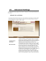
13
Advanced Settings
The advanced settings pages allow users to modify the more complex features of
this device.
Advances wireless
This page allows advanced users who have sufficient knowledge of wireless LAN.
These setting shall not be changed unless you know exactly what will happen
for the changes you made on your router.
Parameter
Beacon Interval
Fragmentation
Threshold
RTS Threshold
Description
The interval of time that this wireless router broadcast
a beacon. Beacon is used to synchronize the wireless
network. The range for the beacon period is between
20 and 1024 with a default value of 100 (milliseconds).
Fragment Threshold specifies the maximum size of
packet during the fragmentation of data to be
transmitted. If you set this value too low, it will result
in bad performance. Enter a value from 256 to 2346.
This value should remain at its default setting of 2347.
Should you encounter inconsistent data flow, only
minor modifications are recommended. If a network
packet is smaller than the preset “RTS threshold” size,
the RTS/CTS mechanism will not be enabled. The
wireless router sends Request to Send (RTS) frames to
a particular receiving station and negotiates the
sending of a data frame. After receiving an RTS, the
wireless station responds with a Clear to Send (CTS)
frame to acknowledge the right to begin transmission.
DTIM
Broadcast SSID
If this option is enabled, the router will automatically
transmit the network name (SSID) into open air at
regular interval. This feature is intended to allow
clients to dynamically discover the router. If this option
is disabled, the router will hide its SSID. When this is
done, the clients cannot directly discover the router
and MUST be configure with the SSID for accessing to
the router. It is used to protect your network from
being accessed easily.
When you finish, click ‘save’ to save the settings made and restart the router so
the settings will take effect after it reboots.
QoS
QoS allows you to classify Internet application traffic by source/destination IP
address and port number. You can assign priority for each type of application and
reserve bandwidth for it. The packets of applications with higher priority will
always go first. Lower priority applications will get bandwidth after higher priority
applications get enough bandwidth. This can let you have a better experience in
using critical real time services like Internet phone, video conference …etc. All the
applications not specified by you are classified as rule name “Others”. The rule
with a smaller priority number has a higher priority; the rule with a larger priority
number has a lower priority. You can adjust the priority of the rules by moving
them up or down.
Classification
Enable/Disable
QoS
You
can
check
“Enable
QoS”
to
enable
QoS
functionality for the WAN port.
Add a rule Enter all the data required for the rule you wish to set and click
Add to save this rule.
Edit a QoS rule Select the rule you want to edit and click “Edit”, then enter
the detail form of the QoS rule. Click “Apply” after editing the form and the
rule will be saved.
Discipline Save allows to save the selected Qos discipline without changing
the current rules.
Rules&Action summary provides an overview of the current effective Qos
settings.
Click ‘Add’ To save and apply the new rule.
UPnP
When the UPnP function is enabled, the router can be detected by UPnP
compliant system such as Windows 7. The router will be displayed in the
Neighborhood of Windows 7, so you can directly double click the router or right
click the router and select “Invoke” to configure the router through web
browser.
Parameter
UPnP
Description
Enable or disable UPnP feature.
Auto-configured
This will allow Upnp enabled applications to open
required ports in your router.
When you finish, click ‘Save’ to save the settings made and restart the router
so the settings will take effect after it reboots.
Routing
The page enables you to define specific route for your Internet and network
data.
Most users do not need to define routes. On a typical small home or office LAN,
the existing routes that set up the default gateways for your LAN hosts and for
the router provide the most appropriate path for all your Internet traffic.
You may need to define routes if your home setup includes two or more
networks or subnets, if you connect to two or more ISP services, or if you
connect to a remote corporate LAN.
Click ‘Add route’ to add a self defined router
Parameter
Destination IP
Adress
Subnet Mask
Gateway IP
adress
Metric
Description
The destination can be specified as the IP address of a
subnet or a specific host in the subnet. It can also be
specified as all zeros to indicate that this route should be
used for all destinations for which no other route is
defined (this is the route that creates the default
gateway).
The network mask of the destination subnet. The default
gateway uses a mask of 0.0.0.0.
Gateway IP that should be used enter an address or
select a pvc channel
Defines the number of hops between network nodes that
data packets travel. The default value is 0, which means
that the subnet is directly one hop away on the local LAN
network.
When you finish, click ‘Save’ to save the settings and restart the router so the
settings will take effect after it reboots.
SNMP
Simple Network Management Protocol (SNMP) is a troubleshooting and
management protocol that uses the UDP protocol on port 161 to communicate
between clients and servers. The router can be managed locally or remotely by
SNMP protocol.
Parameter
SNMP
Get Community
Set Community
Description
Select “Disable” or “Enable” to disable or enable the
SNMP feature.
Name of the read-only community. This read-only
community allows read operation to all objects in the
MIB.
Name of the write-only community. This write-only
community allows write operation to the objects
defines as read-writable in the MIB.
When you finish, click ‘Save’ to save the settings made and restart the router
so the settings will take effect after it reboots.
DDNS
Dynamic DNS (DDNS) allows you to map the static domain name to a dynamic
IP address. You must get an account, password and your static domain name
from the DDNS service providers.
Parameter
Enable
DDNS Provider
Host Name
DynDns Settings
Username
Password
Wildcard support
Description
Check the box to enable DDNS function.
Select your DDNS service provider here. This router
supports DynDNS and TZO service providers
Enter the domain name you’ve obtained from DDNS
service provider.
Enter the username assigned by the DDNS service
provider.
Enter the password assigned by the DDNS service
provider.
Enable or disable the usage of wildcards (i.e. *.* )
When you finish, click ‘Save’ to save the settings made and restart the router
so the settings will take effect after it reboots.
NAT
This page allows viewing or changing of the current status of the NAT for each
VC.
Here it’s possible to set Virtual server or DMZ settings for each virtual circuit.
For more information about the DMZ and virtual server please read chapter 13
Firewall.
TR-69
As a bidirectional SOAP/HTTP-based protocol, it provides the communication
between customer-premises equipment (CPE) and Auto Configuration Servers
(ACS). It includes both a safe auto configuration and the control of other CPE
management functions within an integrated framework. In the course of the
boom of the broadband market, the number of different Internet access
possibilities grew as well (e.g. modems, routers, gateways, set-top box, VoIPphones). At the same time the configuration of this equipment became more
complicated -- too complicated for the end-users. For this reason the TR-069
standard was developed. It provides the possibility of auto configuration of these
access types. The technical specifications are managed and published by
the Broadband Forum. Using TR-069, the terminals can get in contact with the
Auto Configuration Servers (ACS) and establish the configuration automatically.
Accordingly other service functions can be provided. TR-069 is the current
standard for activation of terminals in the range of DSL broadband market.
14 Firewall Settings
The Broadband router provides extensive firewall protection by restricting
connection parameters, thus limiting the risk of hacker attacks, and defending
against a wide array of common Internet attacks. However, for applications that
require unrestricted access to the Internet, you can configure a specific
client/server as a Demilitarized Zone (DMZ).
Firewall
Parameter
Firewall
Description
Enable or Disable the firewall
SPI
Enable or Disable the firewall (Warning: If you
enable SPI, all traffic initiated from WAN will be
blocked)
ACL
This page is used to IP addresses for Access Control. If ACL is enabled only the IP
Addresses that are in the ACL Table can access the CPE.
ACL Enable or disable Access Control
ACL Rule index Select an index number for the rule you are creating.
Active Select if the Rule should be active or not
Secure IP Address Enter the range IP addresses for which this rule should be
effective.
Application Select an application from the list or choose ‘all’.
Interface Select the interface for this rule, ‘WAN’ or ‘LAN’.
IP Filter
Filter Type
Choose the type of filter you wish to use, there are 3 possible types of
filter .
- IP/Mac Filter
- Application filter
- URL block
IP Filter Rule Editing
• IP Filter Rule Index: This is item number
• Active: Select Yes from the drop down list box to enable IP filter rule.
• Source IP Address: The source IP address or range of packets to be
monitored.
•
Subnet Mask: It is the destination IP addresses based on above
destination subnet IP
•
Source Port Number: This Port or Port Ranges defines the port allowed
to be used by the Remote/WAN to connect to the application. Default is
set from range 0 ~ 65535. It is recommended that this option be
configured by an advanced user.
•
•
•
•
•
Destination IP Address: This is the destination subnet IP address.
Subnet Mask: It is the destination IP addresses based on above
destination subnet IP
Destination Port Number: This is the Port or Port Ranges that defines
the application.
Protocol: It is the packet protocol type used by the application, select
either TCP or UDP or ICMP
Rule Unmatched: Select action for the traffic unmatching current rule;
Forward to leave it pass through, and NEXT to check it by the next rule.
IP Filter Listing
• #: Item number.
• Active: Whether the connection is currently active.
• Src IP Mask: The source IP address or range of packets to be monitored.
• Dest IP Mask: This is the destination subnet IP address.
• Src port: This Port or Port Ranges defines the port allowed to be used by
the Remote/WAN to connect to the application. Default is set from range
0 ~ 65535. It is recommended that this option be configured by an
advanced user.
• Dest Port: This is the Port or Port Ranges that defines the application.
• Protocol: It is the packet protocol type used by the application, select
either TCP or UDP or ICMP
Application filter
Here you can choose which applications should be blocked or
allowed access.
Choose which application should be allowed or denied access and click ‘Save’ to
apply the settings.
The URL block
Here it’s possible to block certain websites.
Filter type
Enter the website you wish to block and make sure the rule is active.
Click ‘Save’ to apply the new rule.
URL Filter Listing
Shows all entered URL block rules.
DMZ
The DMZ Host is a local computer exposed to the Internet. When setting a
particular internal IP Address as the DMZ Host, all incoming packets will be
checked by the firewall and NAT algorithms then passed to the DMZ Host.
For example, if you have a local client PC that cannot run an Internet
application (e.g. Games) properly from behind the NAT firewall, then you can
open the client up to unrestricted two-way Internet access by defining a DMZ
Host.
Enable DMZ and enter the IP address for which you want unrestricted access to
the internet in the DMZ Host IP address. Click Apply to save and apply the
settings.
Virtual server
Use the Virtual Server function when you want different servers/clients in
your LAN to handle different service/Internet application type (e.g. Email,
FTP, Web server etc.) from the Internet. Computers use numbers called port
numbers to recognize a particular service/Internet application type. The
Virtual Server allows you to re-direct a particular service port number (from
the Internet/WAN Port) to a particular LAN private IP address and its service
port number.
Local IP This is the LAN client/host IP address that the Public Port number
packet will be sent to.
Start port Here the starting port number must be entered
End port Here the end port number must be entered
Note : The ports from the start port till the End port will be opened
Click the ‘edit icon’ to change an existing rule.
Click ‘Apply’ for the changes to take effect.
15 TOOLBOX Settings
Sitecom Cloud Security
Antivirus software alone is not safe enough. You can now benefit from
additional built-in security in your modem or router. Protect all devices in your
home network against cybercrime while browsing. Activated automatically,
your network and devices are better secured than ever before.
Your Sitecom device comes with a 6 month free Sitecom cloud security
subscription.
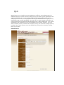
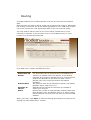
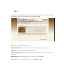
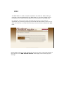
After you have set up your Sitecom device for internet access, open the
webbrowser and enter http://www.sitecomcloudsecurity.com in the address
bar.
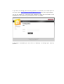
If the device has been properly configured the following web page should be
shown.
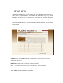
Here you can see which security features are activated.
The Sitecom Cloud Security service offers the following protection options:
-
Anti-Malware
Anti-Phishing
Protection against unsafe websites
Advertisement blocking
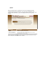
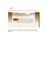
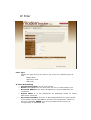
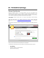
With the protection of unsafe websites activated the Sitecom Cloud Security
will always check if a website is safe. If it is not safe it will inform you that is
not safe to enter.
If you still wish to visit this webpage click on ‘proceed anyway’. Alternatively
click ‘Back to Safety’ so that your security will not be breached.
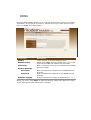
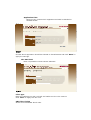
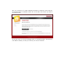
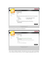
If you wish to change your security options or to extend your subscription at
any time, open http://www.sitecomcloudsecurity.com from your web browser.
You will be asked for a username and password. These can be found on the
backlabel on the bottom of your Sitecom router or modem.
If the login succeeded you can click on ‘Settings’ to change your security
options.
Or click ‘License’ to renew your subscription.
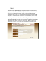
If you wish to disable to Sitecom cloud security at any time, open the webpage
of your Sitecom product and log in with the supplied credentials (these can be
found on the back label on the bottom of your Sitecom device).
Go to Toolbox and select “Sitecom Cloud Security”.
Click the “Disable” radio button and click ‘Apply’ for the settings to take effect.
Password
This page allows you to set the password to access the web server of the router.
If the password you typed in ‘New Password’ and ‘Confirmed Password’ field are
not the same, you’ll see the following message:
“Please retype the new password again when you see above message.”
If the current and new passwords are correctly entered, after you click ‘Apply’,
you’ll be prompted to input your new password:
Please use new password to enter web management interface again, and you
should be able to login with new password.
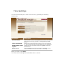
Time Settings
The Time Zone allows your router to set its time; especially for recording
System Log.
Parameter
Current Time
Time Zone Select
Enable SNTP client
update
SNTP server
Description
The current time of the specified time zone. You can set
the current time by yourself or configured by SNTP
server.
Select the time zone of the country you are currently
in. The router will set its time based on your selection.
Check the box to enable router to update time from
SNTP server.
The IP address or the host name of the SNTP server.
You can select from the list or set it manually.
When you finish, click ‘Save’.
The router so the settings will take effect after it reboots.
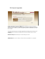
Firmware Upgrade
Enable Automatic firmware update When enabled the router will check for
updates on the firmware if an updated firmware has been released the router will
inform you that a newer firmware is available and offers to download and install
the firmware.
This page also allows you to manually upgrade the firmware for the router. Click
“Browse” button to select the firmware file and click “Upload” button to start
upgrading.
Romfile backup Allows saving all current settings to a file.
IMPORTANT! Do not turn off your router while this procedure is in progress.
Reboot
Whenever you use the Web configuration to change system settings, the
changes are initially placed in temporary storage. To save your change for
future use, you have to click “Apply” to reboot the router. If you have
encountered problems during the configuration, you can click the “OPS” button
in the top panel of the router over 15 seconds to reset default settings.