1
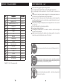
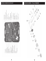
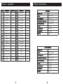
Please dispose of packaging for the product in a responsible
manner. It is suitable for recycling. Help to protect the
environment, take the packaging to the local amenity tip and place
into the appropriate recycling bin.
FOR HELP OR ADVISE ON THIS PRODUCT PLEASE CONTACT YOUR DISTRIBUTOR, OR SIP
DIRECTLY ON:
TEL: 01509500400
EMAIL: [email protected] or [email protected]
www.sip-group.com
Ref: 170812
20
73 Piece
Air Tool Set
07197
Please read and fully understand the instructions in
this manual before operation. Keep this manual
safe for future reference
1
SAFETY INSTRUCTIONS
DECLARATION OF CONFORMITY
These air tools are designed to be used as hand held, hand controlled tools.
DO NOT use the air tool for any other purpose than that for which it was designed.
DO NOT modify the air tool in any way.
DO ensure that only compressed air is used to supply the air tool.
The compressed air supply MUST be at a suitable regulated pressure, with the correct
amount of flow. Pipe work, regulators. Hoses, isolation valves and connection devices MUST be suitable for the intended application correctly installed and maintained
in good condition by a competent person.
Appropriate Personal protective equipment MUST be worn and MUST be designed to
protect against all hazards created. Severe permanent injury can result from using
inappropriate or insufficient protective equipment - Eyes in particular are at risk.
Long hair MUST be tied back; loose clothing MUST NOT be worn. There is a severe risk
of these being drawn in or trapped by the moving parts of the air tool.
Open or damaged compressed air lines present a significant ‘whip’ hazard.
This air tool is electrically conductive DO NOT allow them to come into contact with
any source of electrical supply.
After use wait for the air tool to STOP completely before putting it aside.
When putting the air tool aside you MUST ensure that it placed in a stable position. To
avoid inadvertent operation DO NOT place the air tool where it can be knocked or
moved accidentally either directly or by the air connection hose.
If the air tool is not required or the air supply is interrupted, disconnect the air tool
from the air supply and place in secure storage to prevent unauthorised use.
Ensure the air valve (or trigger) is in the “off” position before connecting to the air supply.
Disconnect the air tool from the air supply before making any adjustments, changing stones etc. and before servicing the tool.
Always keep your air tool clean and lubricated. Daily lubrication is essential to avoid
internal corrosion and possible failure.
Do not overload the tool. Allow the tool to operate at its optimum speed for maximum efficiency.
Do not increase the air pressure above the manufacturers recommended level, as
excessive pressure can cause the tool casing to split. Also this creates excessive
wear on moving parts and possible failure.
Always ensure that the work piece is firmly secured leaving both hands free to control
the tool.
Declaration of Conformity
We
SIP (Industrial Products) Ltd
Gelders Hall Road
Shepshed
Loughborough
Leicestershire
LE12 9NH
England
As the manufacturer's authorised representative within the EC
declare that the
73 Piece Airtool Kit - SIP Pt. No. 07197
Suppliers Part No. RP7857
Conforms to the requirements of the following directive(s), as indicated.
2006/42/EC
Machinery Directive
Signed: …………………………………...
Mr P. Ippaso - Director - SIP (Industrial Products) Ltd
Date: 09/02/2010.
CAUTION: The warnings and cautions mentioned in this user manual can not cover all possible conditions and situations that may occur. It must be understood by
the operator that common sense and caution are factors which cannot be built
into this product, but must be applied.
2
19
PARTS LIST - 150MM AIR HAMMER
SAFETY INSTRUCTIONS….cont
No.
Description
Sip Part No.
1
Hammer Body
AI05-00120
2
Trigger Pin (3×16)
AI05-00121
3
Regulator Valve Pin (3×17.5)
AI05-00122
4
O-ring 8×1.8
AI05-00123
5
Regulator
AI05-00124
6
Trigger
AI05-00125
7
Pin
AI05-00126
8
Pin Seat
AI05-00127
9
Throttle Spring
AI05-00128
10
Air Inlet
AI05-00129
11
Upper valve case
AI05-00130
12
Valve disc
AI05-00130
13
Lower valve case
AI05-00130
14
Piston
AI05-00133
15
Cylinder
AI05-00133
16
Spring Retainer
AI05-00135
N/A
4pc Chisel Set
AI05-00131
*Note PT 11-13 & 14-15 come as a kits
Always wear safety goggles or glasses during operation.
Do not wear watches, rings bracelets or loose clothing when using air tools.
Use as light weight a hose as possible from the tool to the wall or compressor coupling.
In the interests of safety and possible damage to the machine/operator, always ensure that the tool has stopped before putting it down after use.
Always ensure that the accessories such as sanding discs are rated / designed for
use with the particular tool, and are correctly and securely fastened before connecting the tool to the air supply.
When grinding, sanding or cutting always wear an appropriate face mask or respiratory equipment.
Do not use this product in wet or damp conditions.
Do not carry air tools by its air hose.
All sanding discs, attachments etc. must be the correct size and the correct type
and grade for the application.
Sparks and particles resulting from grinding and sanding operations etc. present a
hazard make yourself and bystanders aware of this hazard.
Always wear eye protection when using or maintaining any air tool.
We recommend wearing a face mask or respiratory equipment
when using any air tool; particularly during sanding, grinding or other
operations likely to cause airborne particles.
We recommend wearing ear protection - particularly during extended periods of operation.
18
3
GETTING TO KNOW YOUR TOOL SET
4
EXPLODED DRAWING - 150MM AIR HAMMER
17
OPERATING
INSTRUCTIONS
TECHNICAL SPECIFICATIONS
PARTS LIST - DIE GRINDER
No.
Description
Sip Part No.
No.
Description
Sip Part No.
1
Housing
AI05-00224
20
End plate
AI05-00243
Square Drive
3/8”
2
Valve Bushing
AI05-00225
21
Pin 2×6
AI05-00244
Torque
50ft/lb (68Nm)
3
Trigger
AI05-00226
22
Rotor
AI05-00245
No Load Speed
160 rpm
4
Trigger Pin
AI05-00227
23
Rotor blade
AI05-00246
Average Air Consumption
4 cfm (114 l/min)
5
Spring
AI05-00228
24
Cylinder
AI05-00247
Operating Pressure
6.3 bar (90 psi)
6
Trigger Ring
AI05-00229
25
Washer
AI05-00248
Air Inlet
1/4” bsp
7
Pin 3×18
AI05-00230
26
Bushing
AI05-00249
Sound Pressure
89.6 dB(A)
8
Pin 3×24
AI05-00231
27
Front plate
AI05-00250
Sound Power
100.6 dB(A)
9
O-ring 3.3×1.5
AI05-00232
28
Pin 1.5×4
AI05-00251
Vibration
1.2 m/s2
10
O-ring 4×2
AI05-00233
29
Bearing
AI05-00252
11
Valve Stem
AI05-00234
30
Collet holder
AI05-00253
12
Spring
AI05-00235
31
Retainer ring
AI05-00254
13
Air regulator
AI05-00236
32
Lock ring
AI05-00255
14
O-ring 7×2
AI05-00237
33
Collet
AI05-00256
15
O-ring 11×2
AI05-00238
34
Collet nut
AI05-00257
16
Screw cap
AI05-00239
35
Wrench
AI05-00258
17
Muffle cover
AI05-00240
36
Wrench
AI05-00259
18
Air inlet
AI05-00241
N/A
10pc Stone Assortment Kit
06731
19
Bearing
AI05-00242
N/A
Sanding Roll
06741
16
3/8” Ratchet
½” Impact Wrench
Square Drive
½”
Torque
230ft/lb (310Nm)
No Load Speed
7000 rpm
Average Air Consumption
8 cfm (228 l/min)
Operating Pressure
6.3 bar (90 psi)
Air Inlet
1/4” bsp
Sound Pressure
84.4 dB(A)
Sound Power
95.4 dB(A)
Vibration
2.6 m/s2
5
TECHNICAL SPECIFICATIONS….cont
EXPLODED DRAWING - DIE GRINDER
1/4” Die Grinder
Collet Size
¼”
No Load Speed
25,000 rpm
Average Air Consumption
3 cfm (86 l/min)
Operating Pressure
6.3 bar (90 psi)
Air Inlet
1/4” bsp
Sound Pressure
82.4 dB(A)
Sound Power
93.4 dB(A)
Vibration
0.8 m/s2
150mm Air Hammer
Chisel Shank
10.2mm
Bore Diameter
19.05mm
Blow Per Min
4500 rpm
Average Air Consumption
2.8 cfm (79 l/min)
Operating Pressure
6.3 bar (90 psi)
Air Inlet
1/4” bsp
Sound Pressure
96.9 dB(A)
Sound Power
107.9 dB(A)
Vibration
14.6 m/s2
6
15
PARTS LIST - RATCHET WRENCH
GUARANTEE
No.
Description
Sip Part No.
No.
Description
Sip Part No.
1
Valve Plug
AI05-00181
23
Clamp nut
AI05-00203
2
O-ring 9.5×2
AI05-00182
24
Ratchet Housing
AI05-00204
3
Spring
AI05-00183
25
Needle Bearing
AI05-00205
4
O-ring 4×1.8
AI05-00184
26
Bearing shell
AI05-00206
5
Valve Stem
AI05-00185
27
Crank shaft
AI05-00207
6
Air inlet
AI05-00186
28
Drive bushing
AI05-00208
7
Roll Pin 3×24
AI05-00187
29
Ratchet Yoke
AI05-00209
8
Trigger
AI05-00188
30
Spring
AI05-00210
9
Housing
AI05-00189
31
Bushing
AI05-00210
10
Rear Bearing
AI05-00190
32
Lock Pin 2×6
AI05-00210
11
Rear Plate
AI05-00191
33
Reverse Button
AI05-00210
12
Rotor Blade
AI05-00192
34
Washer
AI05-00210
13
Rotor
AI05-00193
35
Ratchet Pin
AI05-00210
14
Pin 1.5×6
AI05-00194
36
Ratchet Pawl
AI05-00210
15
Rotor Housing
AI05-00195
37
Ratchet Anvil
AI05-00210
16
Front Plate
AI05-00196
38
Steel ball
AI05-00210
17
Bearing
AI05-00197
39
Spring
AI05-00210
18
V Washer
AI05-00198
40
Spring
AI05-00210
19
Thread Ring Gear
AI05-00199
41
Steel ball
AI05-00210
20
Idler Gear
AI05-00200
42
Washer
AI05-00210
21
Idler Gear Pin
AI05-00201
43
Retainer ring 30
AI05-00210
22
Idler Gear Seat
AI05-00202
Guarantee:
This SIP air tool is covered by a 12 month parts and labour warranty covering failure
due to manufacturers defects. This does not cover failure due to misuse or operating
the machine outside the scope of this manual.
This guarantee does not cover consumables.
In the unlikely event of warranty claims, contact your distributor as soon as possible.
Proof of purchase will be required before any warranty can be honoured.
Failure to lubricate your air tool will shorten its working life and reduce performance.
Also note the warranty does not cover rusting air tools and tools failed due to the lack
of lubrication.
Note: Proof of purchase will be required before any warranty can be honoured.
OPERATING INSTRUCTIONS
Air Supply:
1.Ensure the air tool air valve (trigger) is in the “off” position before connecting to the air
supply.
2.You will require an air pressure of 90psi, and an air flow according to specification of
each individual tool.
3.WARNING! Ensure the air supply is clean and does not exceed 90psi while operating
the tools. Too high an air pressure and unclean air will shorten the product life due to
excessive wear, and may be dangerous causing damage and/or personal injury.
4.Drain the air tank / receiver of the compressor daily. Water in the air line will damage
the air tools.
5.Clean air inlet filter weekly. Recommended hook-up procedure is shown in fig 1.
6.Line pressure should be increased to compensate for unusually long air hoses (over
8 metres). The minimum hose diameter should be 1/4” I.D. and fittings must have the
same inside dimensions.
7.Keep hose away from heat, oil and sharp edges. Check hose for wear, and make
certain that all connections are secure.
*Note PT`s 30-43 (Tune-up kit) come as a kit
14
7
OPERATING INSTRUCTIONS….cont
EXPLODED DRAWING - RATCHET WRENCH
Lubricator
Quick Connector
Quick Connector
Filter
Cut Off Valve
Tool
Fig. 1
Quick Coupler
Air Hose
Quick Coupler
Regulator
Compressor
MAINTENANCE
Warning! Always disconnect the air tool from air supply before changing accessories, cleaning or performing maintenance tasks. Replace or
repair damaged parts - Use genuine parts only; non-authorized parts
may be dangerous, reduce the performance and life of the tool and
will invalidate the warranty. Servicing or repairs should only be performed by a competent person.
1. Ensure that the air tool is lubricated daily, ideally with an inline oiler, see Fig. 1, or if
not with a few drops of air tool oil dripped into the air inlet.
2.Clean the tools after use. DO NOT use the tool with worn, or damaged parts - replace / have them replaced immediately.
3.Loss of power or erratic action may be due to the following:
a.Excessive drain on the air line. Moisture or restriction in the air line. Incorrect size or
type of hose connectors.
b.Grit or gum deposits in the air tool may also reduce performance. If your model has
an air strainer (located in the area of the air inlet), remove the strainer and clean it.
Flush the air tool out with gum solvent oil or an equal mixture of SAE No 10 oil and
paraffin. Allow to dry before use.
5.When not in use, disconnect from air supply, clean and store in a safe, dry, childproof location.
8
13
PARTS LIST - IMPACT WRENCH
LUBRICATION
No.
Description
Sip Part No.
No.
Description
Sip Part No.
1
Protecting Rubber
AI05-00136
24
Bolt M5×20
AI05-00159
2
Housing
AI05-00137
25
Rear Protection Rubber
AI05-00160
3
Bolt M8×6
AI05-00138
26
Valve Sleeve
AI05-00161
4
Anvil Bushing
AI05-00139
27
Reverse Valve
AI05-00162
5
Anvil Collar
AI05-00140
28
O-ring 6.7×1.8
AI05-00163
6
O-ring 7.5×1.8
AI05-00141
29
Valve Stem
AI05-00164
7
Anvil
AI05-00142
30
Seal
AI05-00165
8
Hammer Pin
AI05-00143
31
Steel ball
AI05-00166
9
Hammer Cage
AI05-00144
32
Inlet Spring
AI05-00167
10
Hammer Dog
AI05-00145
33
Air Inlet Plug
AI05-00168
11
Drive Cam
AI05-00146
34
Air Inlet Cover
AI05-00169
12
Ball Bearing
AI05-00147
35
Spring
AI05-00170
13
Oil seal
AI05-00148
36
O-ring 8.5×1.8
AI05-00171
14
Front End plate
AI05-00149
37
Air Regulator
AI05-00172
15
Rotor blade
AI05-00150
38
Bolt
AI05-00173
16
Rotor
AI05-00151
39
Pin 3×14
AI05-00174
17
Pin 3×10
AI05-00152
40
Trigger
AI05-00175
18
Rotor Housing
AI05-00153
41
Exhaust cover
AI05-00176
19
Pin 3×17.5
AI05-00154
42
Bolt
AI05-00177
20
Rear End Plate
AI05-00155
43
Bolt M5×6
AI05-00178
21
Gasket
AI05-00156
44
Spring
AI05-00179
22
Rear Cover
AI05-00157
45
Pin
AI05-00180
23
Washer
AI05-00158
An automatic in-line filter-regulator-lubricator is recommended (see Fig.1) as it increases tool life and keeps the tool in sustained operation. The in-line lubricator
should be regularly checked and filled with air tool oil.
Proper adjustment of the in-line lubricator is performed by placing a sheet of paper
next to the exhaust ports and holding the throttle open approximately 30 seconds.
The lubricator is properly set when a light stain of oil collects on the paper. Excessive
amounts of oil should be avoided.
In the event that it becomes necessary to store the tool for an extended period of
time (overnight, weekend, etc.), it should receive a generous amount of lubrication
at that time. The tool should be run for approximately 30 seconds to ensure oil has
been evenly distributed throughout the tool. The tool should be stored in a clean and
dry environment.
It is most important that the tool be properly lubricated by keeping the air line lubricator filled and correctly adjusted. Without proper lubrication the tool will not function
correctly and parts will wear prematurely.
Use the proper lubricant in the air line lubricator. The lubricator should be of low air
flow or changing air flow type, and should be kept filled to the correct level. Use only
recommended lubricants, specially made for pneumatic applications. Substitutes
may harm the rubber compounds in the tools O-rings and other rubber parts.
CAUTION: If a filter/regulator/lubricator is not installed on the air system,
air operated tools should be lubricated at least once a day or after 2
hours work with 2 to 6 drops of oil, depending on the work environment,
directly through the male fitting in the tool housing.
TROUBLE SHOOTING
The following table lists the common operating issues, with problems and solutions.
If any of the following symptoms appears during operation, stop using
the tool immediately, or serious personal injury could result. Only a qualified person or an authorized service centre can perform repairs or replace parts of tool.
12
9
TROUBLE SHOOTING….cont
EXPLODED DRAWING - IMPACT WRENCH
Always
PROBLEMS
wear safety goggles
glasses during operation.
POSSIBLEorCAUSES
REMEDIES
Do not wear watches, rings bracelets or loose clothing when using air tools.
Using as light weight a hose as possible from the tool to the wall or compressor couTool runs at normal speed but Motor parts worn.
Lubricate clutch housing.
pling.
loses
power under load
Cam clutch worn or sticking Check for excess clutch oil. Clutch cases
In the interests of safety due
andtopossible
damage to need
the machine/operator,
always enlack of lubricant.
only be half full. Overfilling can cause
sure that the machine has stopped before puttingdrag
it down
after
use.
on high speed clutch parts, ie. a typical
oiled/lubricated
wrench
requires 1/2for
ounce
Always ensure that the accessories such as sanding
discs are rated
/ designed
of oil.
use with this sander, and are correctly and securely
fastened before connecting the
NOTE: Heat usually indicates insufficient
tool to the air supply.
grease in chamber. Severe operating condiWhen grinding, sanding or cutting always wear antions
appropriate
mask orlubrication.
respiramay require face
more frequent
tory equipment.
Do not use this product in wet or damp conditions.
Do not carry air tools by its air hose.
Tool
runsair
slowly.
flow is low to
Motor
with dirt
Check
air inlet
filter for blockage.
This
tool Air
is designed
be parts
usedjammed
as a hand
held,
hand
controlled
sander
from exhaust
particles.
for the purpose of sanding
metals, plastics and various
Pour air other
tool lubricating
materials.
oil into air inlet as per
Power
regulator size
in and
closed
All sanding discs must be
the correct
theinstructions.
correct type and grade for the
position.
Operate tool in short bursts quickly reversing
application.
Air flow blocked by dirt.
rotation back and forth where applicable.
Sparks and particles resulting from grinding present
a hazard make yourself and byRepeat above as needed. If this fails return
standers aware of this hazard.
to service centre.
Tools will not run. Air flows One or more motor vanes
freely from exhaust
stuck due to material build
up.
Pour air tool lubricating tool into air inlet.
Operate tool in short bursts of forward and/or
reverse rotation where applicable.
Tap motor housing gently with plastic mallet.
Disconnect supply. Free motor by rotating
drive shank manually where applicable
If tool remains jammed return to service
center.
Tool will not shut off
‘O’ rings throttle valve dis- Replace ‘O’ ring or return to service center.
lodged from seat inlet valve.
Note: Repairs should be carried out by a qualified person.
10
11