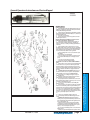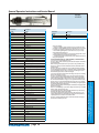
1
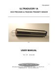
H ENRY T OOLS
Models
42-GHL
Industrial Airtools at Work
General Safety and Maintenance
Manual
Model
Number
42-GHL
Exhaust
Direction
Side
Throttle
Type
(L) Lever
or
(K)
Safety
Lever
Speed
1500022000
R.P.M.
RatedPower
Output
0.9 H.P
.675 W
Case
Material
Alum.
Weight
Aluminum
Length
Steel
2 1/2 lbs
1.1kg Alum case only
8 5/8”
219m
Diameter Front
Housing
Air
Consumption
1.50 Inch 25 cfm
(38.1
(11.8 L/S)
mm)
Spindle
Thread Type
3/8-24 X 1.0
Inch
The Henry Tool Co., Manufactured by Henry Tools
498 So. Belvoir Blvd., South Euclid, OH 44121 U.S.A.
Ph: (216) 291-1011 or (800) 826-5257 ● Fax: (216) 291-5949 or (800) 303-2800
Email: [email protected] ● Website: www.Henrytools.com
General Operators Instructions and Service Manual
Models
42-GHL
Revised 12/12/09
www.HenryTools.com | Page 37
The Henry Tool Co., Manufactured by Henry Tools
ALWAYS COMPLY WITH:
1. General Industry Safety & Health Regulations, Part 1910,
OSHA 2206, available from: Sup’t of Documents; Government
Printing Office; Washington DC 20402
2. Safety Code for Portable Air Tools, ANSI B186.1 available
from: American National Standards Institute, Inc.; 1430 Broadway; New York, NY 10018
3. State and Local regulations.
4. Portions of the above codes and regulations are listed
below for quick reference.
THESE EXCERPTS ARE NOT INTENDED TO BE ALL INCLUSIVE STUDY AND COMPLY WITH ALL REGULATIONS!
1.
Always turn off the air supply and disconnect the air
supply hose before installing, removing or adjusting any
accessory on this tool, or before performing any maintenance
on this tool.
2.
After mounting a wheel or other abrasive accessory,
the Grinder shall be run in a protected enclosure, at gradually
increasing speed, for at least 60 seconds. When starting work
with a cold wheel, apply it gradually to the workpiece until it
becomes warm. Do not continue to use a grinder if:
• The speed rating of the accessory is less than the speed
of the grinder
• If tool vibrates repair immediately.
• You sense changes in tool speed or an unusual increase
in noise that would indicate tool is running at excessive
speed.
• You notice excessive end play in spindle
• You hear any unusual sound from grinder
RETURN THE TOOL TO THE TOOL CRIB FOR SERVICE IMMEDIATELY.
3.
Make certain no one is in front of or in line with the wheel
or other abrasive accessory. Be aware that it may fail at this
time if it is defective, improperly mounted or the wrong size
and speed. Stop immediately if considerable vibration or other
defects are detected. Shut off the air supply and determine
the cause.
4.
OPERATOR PROTECTIVE EQUIPMENT - Wear goggles or
face shield at all times tool is in operation. Other protective
clothing shall be worn, if necessary. SEE REGULATIONS.
5.
Keep hands, loose clothing and long hair away from
rotating end of tool.
6.
Anticipate and be alert for sudden changes in motion
during start up and operation of any power tool.
7.
Keep body stance balanced and firm. Do not overreach
when operating this tool. High reaction torques can occur at or
below the recommended air pressure.
8.
Tool accessories may continue to rotate briefly after
throttle is released.
9.
Air powered tools can vibrate in use. Vibration, repetitive
motions or uncomfortable positions may be harmful to your
hands and arms. Stop using any tool if discomfort, tingling feeling or pain occurs. Seek medical advice before resuming use.
10. This tool is not designed for working in explosive atmospheres. Do not use this tool on materials whose dust or fumes
can cause a potentially explosive environment.
11.
12. This tool is not insulated against electric shock.
13. Product Safety information - When Placing the Tool in
Service
• NEVER MODIFY ANY PART OF THIS TOOL!!!! Always
install, operate, inspect and maintain this product in accordance with all applicable standards and regulations (local,
state, country, federal, etc.).
• Always use clean, dry air at 90 psig (6.2 bar/620 kPa)
maximum air pressure at the inlet. Higher pressure may
result in hazardous situations including excessive speed,
rupture, or incorrect output torque or force.
• Be sure all hoses and fittings are the correct size and are
tightly secured.
• Install a properly sized Safety Air Fuse upstream of hose
498 So. Belvoir Blvd., South Euclid, OH 44121 U.S.A.
Ph: (216) 291-1011 or (800) 826-5257 ● Fax: (216) 291-5949 or (800) 303-2800
Email: [email protected] ● Website: www.Henrytools.com
GRINDER SAFETY
General Operators Instructions and Service Manual
Models
42-GHL
Part Number
Description
320-9R
O-Ring
Part Number
320-9-W
Wafer
GUARDS
400-2-G (w/400-44)
Cylinder(18000RPM STANDARD)
501-4A
4” Guard
400-2
Cylinder 15000RPM
412888
3” Guard (501-3A)
400-3
Rear Plate(Standard)
400-3A
Rear Plate(15000RPM)
400-5
Rotor
400-6
Blade(5 are req’d)
400-7
Front Thrust
400-9
Rear Bearing (Sealed) (590004)
400-10
Key
400-27
Bushing
400-39
Lock Ring (844941)
400-44
Pin
Collet Spacer 3/8”
400-77J
3/8” Threaded Spacer
400-G-42
Washer(2 Req’d)
400-G-47
3/8” Nut
HT-1010
Heavy Duty Collet Assembly (1/4”)
HT-1010-3/8
Heavy Duty Collet Assembly (3/8”)
1100-056
Wrench 9/16”
1100-100
Wrench 1”
1100-075
Wrench 3/4”
402-134
Muffler Screen
400-51
O-Rlng
400-G-1
Case (Alum.) (412431)
400-G-1-S
Case (STEEL)
400-G-4
Alum.Coupling
400-G-4-S
Steel Coupling
400-G-11
Bearing(2 Req’d)
400-G-17
Alum. Exhaust Sleeve
400-G-17-S
Steel Exhaust Sleeve
400-G-26
Valve Lever
400-G-29
Valve (412451)
400-GH-1-3
Extended Case (Aluminum)
400-GH-14-3
Spindle (40GHL) (412477)Non-Govrned
500-G-44
Wheel Washers for 4” Wheels
500-G-42-A
Flange, 1/2-20 Thread
500-16B
Front Bearing CAP
500-21
Seal(Optional)
501-13
Bearings (412891)(PAIR)
700-37
Lever Pin
832636
T.V. Cap Gasket
869311
Throttle Valve Cap
www.HenryTools.com | Page 38
• DO NOT MODIFY THE TOOL, SAFETY DEVICES, OR ACCESSORIES.
• Use accessories recommended by Henry tools.
• Do not use this tool if the actual free speed exceeds the rated rpm. Check the free
speed of the Grinder
before mounting a wheel, after all tool repairs, before each job and after every
8 hours of use. Check speed with a calibrated tachometer, without the abrasive
product installed.
• Do not use any wheel or other abrasive accessory whose maximum operating
speed, as defined by its manufacturer, is less than the rated speed of the Grinder.
• Inspect all grinding wheels for chips or cracks prior to mounting. Do not use a
wheel that is chipped, cracked or otherwise damaged.
• Inspect arbor, threads & clamping devices for damage & wear prior to mounting
wheel or other abrasive accessory.
• Do not use a grinding wheel that has been exposed to freezing temperatures,
extreme temperature changes, high humidity, solvents, water or other liquids.
• Make certain grinding wheel or other abrasive accessory properly fits the spindle. The wheel should not fit too snugly or too loosely. Plain hole wheels should
have about .007” (0.17 mm) maximum diametral clearance. Do not use reducing
bushings to adapt a wheel to any arbor unless such bushings are supplied by and
recommended by the wheel manufacturer.
• Always use the wheel flanges furnished by the manufacturer and appropriate for
the wheel size and type.
Never use a makeshift flange or plain washer. Flanges should be in good condition
and free of nicks, burrs and sharp edges.
• Ensure that the thread type and size of the threaded abrasive product exactly
matches the thread type and size of the spindle.
• Prevent the spindle end from touching the bottom of the hole of cups, cones
or plugs with threaded holes, intended to be mounted on machine spindles, by
comparing dimensions and other relevant data for them.
• Do not use an unguarded grinder unless used for internal work and only operated when the work offers protection.
Revised 12/12/09
The Henry Tool Co., Manufactured by Henry Tools
400-76-J-3/8”
and use an anti-whip.
• Always turn off the air supply, bleed the air pressure and disconnect the
air supply hose before installing, removing or adjusting any accessory on this
tool, or before performing any maintenance on this tool or any accessory.
• Ensure that the grinding wheel or other abrasive accessory is correctly
mounted and tightened before use.
• Always replace a damaged, bent or severely worn wheel guard. Do not use
a wheel guard that has been subjected to wheel failure.
• • Guard opening must face away from the operator. Bottom of wheel must
not project beyond guard.
498 So. Belvoir Blvd., South Euclid, OH 44121 U.S.A.
Ph: (216) 291-1011 or (800) 826-5257 ● Fax: (216) 291-5949 or (800) 303-2800
Email: [email protected] ● Website: www.Henrytools.com
ACCESSORIES
Description
General Operators Instructions and Service Manual
Revised 12/12/09
run tool to allow oil to be carried to interior.
DISASSEMBLY
1. Disconnect air supply and remove all wheels and accessories.
2. Clamp wrench flats of case(400-GH-1) in vise and unscrew backhead(400-G-4).
Unscrew case (400-G-1) and remove it. Lift off exhause sleeve (400-G-17).
3. Remove snap ring(400-39) and(320-9R) and (320-9R).
4. Remove assembly from vise. Place brass jaws in vise. Clamp cylinder and rear
thrust assembly in vise. Using a 3/16” punch, tap out lightly on the end of the
spindle(400-GH-14-3). This will allow the cylinder(400-2[G]), end plate(400-3),
bearing(400-9), and blades(400-6) to be removed.
5. Lightly grasp Cylinder(400-2G) and endplate (400-3) in vise. Using a
5/16”punch, tap out bearing(400-9) from end plate(400-3). Being careful not to
drop the entire assembly on the floor after freeing the bearing.
6. Place rotor(400-5), whcih is stiill attached to the spindle, in a vise with brass
jaws. Unscrew wheel flange(500-G-42A)(NOTE: right hand thread). Remove rotor, key(400-10), and front thrust plate(400-7).
7. Remove brass jaws from vise. Clamp wrench flats of case(400-G-1) in vise.
Remove bearing cap(500-16B)(left hand thread). Using an arbor press, press on
the front of the spindle. This will enable the rear bearing(400-G-11) to drop out
and the spindle to be removed.
8. Using a 3/4” round bar, tap out bearing (501-13) from case (400-GH-1).
REASSEMBLY
1. Press bearings (501-13) into recess in front of the case(400-GH-1-3). Spin
(500-16B) back onto (400-GH-1)(NOTE: Left Hand Thread) a. Press spindle (400GH-14-3) through bearings from the rear.
2. Press bearing (400-G-11) into case from the rear and place the front thrust
plate (400-7) over the bearing.
3. Place case (400-GH-1-3) in vise by the flats. Tighten bearing cap(500-16B)(Left
hand thread). Make sure (500-16B) is tight.
4. Replace key(400-10) and drop rotor(400-5) into place. With BRASS jaws
installed on vise, grab hold of rotor(400-5). Replace flange(500-G-42A) onto
spindle (400-GH-14) and tighten.
5. Place cylinder (400-2G) over rotor (400-5). Place rear thrust (400-3) on
cylinder(make sure pin in cylinder lines up with hole in rear plate(400-3). Press
bearing(400-9) into rear thrust with a suitable bearing driver.
6. Place o-ring(320-9R), washer(320-9W) in rear thrust. Place snap ring(400-3)
into groove.
7. Place O-ring (400-51) onto case(400-G-1). Place case(400-G-1) into sleeve
(400-G-17). Slide this assembly onto case(400-GH-1) and hand tighten.
8. Optional Step: To make sure there are no air leaks in handle, unscrew cap
(869311) and lift out spring(400-G-34)and throttle valve (400-G-29). Remove
oring(400-G-31) with a sharp tool and replace with a new O-ring.
www.HenryTools.com | Page 39
The Henry Tool Co., Manufactured by Henry Tools
This tool is designed to operate on 90 psig(6.2 bar)
maximum air pressure with 1/4”(8mm) hose. Do
not use any wheel having an operating speed lower
than the actual free speed on grinder.
SAFETY
1. Check speed of tool with tachometer before every wheel & burr change. If RPM excees rated speed
stamped on tool, servicing is required.
2. Inspect grinding wheels for bends, chips, nicks,
cracks or severe wear. If the wheel has any of these,
or has bee soaked in liquids do not use. On brushes
check for loose wires that may fly off in operation.
3. Start new grinding wheels under a steel bench.
Run at full throttle for one minute. Defective wheels
usually come apart immediately. When starting a
cold wheel apply to the work slowly, allow wheel to
warm up gradually.
Model 42GH grinders are equipped with a guard
from the manufacturer. A guard is not needed for:
a.) mounted wheels two inches (50 mm) or smaller;
b.) grinders used for internal work, while within the
work being ground.
4. At least one-half of the mandrel length (i.e.
mounted wheel, burr, etc.)must be inserted into the
collet. Secure collet chuck tightly.
5. Before mounting or removing a wheel or carbide
burr disconnect grinder from air supply. The wheel
should fit properly on arbor; do not use bushings or
wheel flanges to adapt a wheel to any arbor unless
recommended by manufacturer. (Wheel flanges
should be at least 1/3 the diameter of the grinding
wheel.)
6. Wear safety goggles and other protective clothing. Continuous exposure to vibration may cause
injury to hands and arms.
7. Properly maintained air tools are less likely to
fail or cause accidents. If tool vibrates unusually or
produces an unusual noise, repair immediately.
LUBRICATION
Check for wet or dirty air. Excessive moisture in the
air supply tends to wash lubricant away from the
working parts of the tool and rust or corrode the
interior. Grit will damage the interior by scoring
closely fitted parts, and impede the action of the
tool.
If the above are found in order, disconnect tool and
pour a liberal amount of recommended oil or an
SAE #10 oil cut with an equal quantity of kerosene
into the air inlet. Operate the tool to allow lubricant
to flush accumulated gum and grit out the exhaust.
If outside factors are not to blame, dissassemble
the tool, clean and inspect all parts and replace
those worn or broken. Coat parts with airtool oil
and reassemble. Pour about 1/2 oz. in air inlet and
498 So. Belvoir Blvd., South Euclid, OH 44121 U.S.A.
Ph: (216) 291-1011 or (800) 826-5257 ● Fax: (216) 291-5949 or (800) 303-2800
Email: [email protected] ● Website: www.Henrytools.com
Models
42-GHL