1
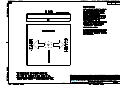
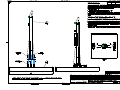
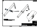
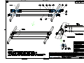
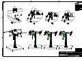
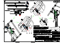
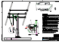
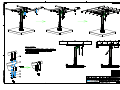
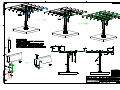
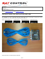
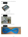
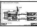
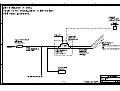
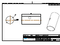
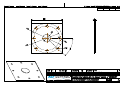
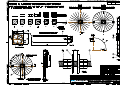
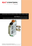
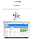
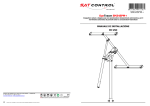
Want to get more?
Company:
SAT CONTROL d.o.o.
Poženik 10
SI-4207 CERKLJE
SLOVENIA – EUROPEAN UNION
Web site: www.solar-motors.com e-mail: [email protected]
INSTRUCTIONS FOR INSTALATION AND USE
For: SOLAR TRACKER DUAL AXIS SM44M3V15P FOR 15 PANELS DIM 990X1650 MM OR 25M2
Model: SM44M3V15P
Code: 3 8 3 1 0 6 3 9 0 1 5 3 2
Date: 01-08-2011
Design approved by:
Director BOLKA BOGDAN ing.
COPYRIGHT ALL DRAWINGS!
page 1
CONFIDENTIONAL ALL DRAWINGS!
CAD DRAWING DISCLAIMER
CAD terms of use
All intellectual property rights (including, without limitation, all copyright and design rights) subsisting in the CAD drawings
and related information belongs to SAT CONTROL d.o.o..
The USER may not, under any circumstances use or allow the use of CAD drawings with any product or system other
than SAT CONTROL d.o.o. products or systems.
The reproduction and use of this material is only authorised for purposes connected with the specification or use of SAT
CONTROL d.o.o. products and systems. The USER of this information is authorised to reproduce and distribute exact
copies or exact extracts of CAD drawings for the sole purpose of detailing, specifying, using, and promoting the use of
SAT CONTROL d.o.o. products and systems.
This information may not contain the full details required for construction. It is the USER's responsibility to ensure full
construction performance specifications and to ensure specification and installation of solar tracker’s products and
systems are in accordance with solar tracker’s technical datasheets or publications. Appropriate expert advice should
always be obtained to ensure suitability of these drawings for your specific application.
SAT CONTROL d.o.o. accepts no responsibility or liability for any loss or damage caused to the USER or any third party
through any use of the CAD drawings or related information, which use contravenes these terms of use, including but not
limited to, any use of the CAD drawings and related information:
•(a) with any product or system other than SAT CONTROL d.o.o. Limited's products or systems; and
•(b) where the CAD drawings and related information are modified in any way.
The USER is deemed to accept these terms of use. IF YOU DO NOT AGREE
TO THE TERMS OF USE, DO NOT USE THE SAT CONTROL D.O.O. CAD DRAWINGS.
USAGE DISCLAIMER!
Terms of USE
All drawings and all documentation are copyright by SAT CONTROL d.o.o. and is marked as “Confidentional”
page 2
Want to get more?
DECLARATION OF CONFORMITY
according to ISO/IEC Guide 22 and EN 45014
Company/Manufacturer’s Name: Sat Control d.o.o.
Address: Poženik 10, SI-4207 Cerklje, Slovenia / EU
declares under its sole responsibility, that the product
Product name:
Solar Tracker SM44M3V15P
Model number:
SM44M3V15P
Product options:
(+) All
conforms to the following directives and/or standards
-
EN 55013 :97 +A12 :97 +A13 :97 +A14 :00
EN 55020 :95 +A11 :97 +A12 :00 +A13 :00 +A14 :00
EN61000-3-3 :97
SIST EN 61000-3-2 :97 +A1 :99 +A2 :00
IEC 60065 :98
SIST EN 1990:2004 Eurocode
SIST EN 1991-1-1:2004 Eurocode 1 - 1-1
SIST EN 1991-1-3:2004 Eurocode 1 - 1-3
SIST EN 1991-1-4:2005 Eurocode 1 - 1-4
SIST EN 1993-1-1:2005 Eurocode 3 - 1-1
SIST EN 1993-1-3:2007 Eurocode 3 - 1-3
SIST EN 1993-1-8:2005 Eurocode 3 - 1-8
SIST EN 1993-1-9:2005 Eurocode 3 - 1-9
Supplementary Information:
The product herewith complies with the requirements of the following Directives or standards and carries the CEmarking accordingly:
- the Electromagnetic compatibility (EMC) directive 89/336/EEC
- Low voltage equipment directive 73/23/EEC
- Basic projection standards
- Standard for guidelines and methods for checking the load of structures
- Standard of influences on the constructions - The overall impacts - Densities, self-weight, imposed loads
of buildings
- Standard of influences on the constructions - The overall impacts - Snow loads
- Standard of influences on the constructions - The overall impacts - Wind loads
- Standard for design of steel structures: General rules and rules for buildings
- Standard for design of steel structures: General rules - Supplementary rules for cold-formed profiles and
sheet metal
- Standard for design of steel structures: Design of joints
- Standard for design of steel structures: Mechanical weariness
Signed for and on behalf of:
Director of
Sat Control d.o.o.
Bogdan Bolka
_______________________________
(name, function) (signature, stamp)
Place and date of issue
Cerklje, 1st August 2011
Update: 8th August 2012
File name: Declaration of Conformity for Solar Tracker - SM44M3V15P dated 01-08-2011.doc
page 3
Declaration of conformity no:
.
page 4
page 5
page 6
page 7
page 8
page 9
page 10
36
page 11
page 12
page 13
36
page 14
page 15
page 16
page 17
page 18
page 19
page 20
Want to get more?
Manufacturer:
SAT CONTROL d.o.o.
Poženik 10
SI-4207 CERKLJE
SLOVENIA – EUROPEAN UNION
Web site: www.solar-motors.com e-mail: [email protected]
INSTRUCTIONS FOR INSTALATION AND USE
For: ASSEMBLY OF SET JUNCTION BOX WITH INSTALLED SOLAR POSITIONER CONTROLLER MICRO
POZSOL36A IN AND 2 PCS CABLES FOR LINEAR MOTOR 2M AND 5M
Models: JBOXSETSPMN1-TC
POZSOL36A1DR
KABINTSM4M3L2OP
Codes:
WHICH INCLUDE FOLLOWING PRODUCTS BELOW:
page 21
KABINTSM4M3L5OP
For: Set Jun. Box 190x140x70 w inst. sol. poz., DIN rail, glands, cable
Model: JBOXSETSPMN1-TC
Code:
For: Solar Positioner 2-axis mod. MICRO, USB-RS485, DIN rail
Model: POZSOL36A1DR
Code:
For: Int. Cable SM4M3 w con. 7pins->OPEN, L=2m 2x1+5x0.22
Model: KABINTSM4M3L2OP
Code:
page 22
For: Int. Cable SM4M3 w con. 7pins->OPEN, L=5m 2x1+5x0.22
Model: KABINTSM4M3L5OP
Code:
CAD DRAWING DISCLAIMER
CAD terms of use
All intellectual property rights (including, without limitation, all copyright and design rights) subsisting in the CAD drawings
and related information belongs to SAT CONTROL d.o.o..
The USER may not, under any circumstances use or allow the use of CAD drawings with any product or system other
than SAT CONTROL d.o.o. products or systems.
The reproduction and use of this material is only authorised for purposes connected with the specification or use of SAT
CONTROL d.o.o. products and systems. The USER of this information is authorised to reproduce and distribute exact
copies or exact extracts of CAD drawings for the sole purpose of detailing, specifying, using, and promoting the use of
SAT CONTROL d.o.o. products and systems.
This information may not contain the full details required for construction. It is the USER's responsibility to ensure full
construction performance specifications and to ensure specification and installation of solar tracker’s products and
systems are in accordance with solar tracker’s technical datasheets or publications. Appropriate expert advice should
always be obtained to ensure suitability of these drawings for your specific application.
SAT CONTROL d.o.o. accepts no responsibility or liability for any loss or damage caused to the USER or any third party
through any use of the CAD drawings or related information, which use contravenes these terms of use, including but not
limited to, any use of the CAD drawings and related information:
•(a) with any product or system other than SAT CONTROL d.o.o. Limited's products or systems; and
•(b) where the CAD drawings and related information are modified in any way.
The USER is deemed to accept these terms of use. IF YOU DO NOT AGREE
TO THE TERMS OF USE, DO NOT USE THE SAT CONTROL D.O.O. CAD DRAWINGS.
USAGE DISCLAIMER!
Terms of USE
All drawings and all documentation are copyright by SAT CONTROL d.o.o. and is marked as “Confidentional”
page 23
STEP 1: Unscrew the 4 pcs of screws and open the box and loose the main fuse (slow type)
STEP 2: Push through the gland the power supply cable and connect it where is written + plus and – minus. Be carefull to
polarity. Do not forget to wire the grounding wire too where is written Shields – earthing. The outdoor cable need to be 3
2
wires with cross section of 3 x 2,5mm , isolation of 1000V, UV stable and powered with the 24V DC 5A. Do not forget to
tight the gland on cable.
STEP 3: Push through the gland the RS485 cable. This is the 3 wires cable (one twisted pair and – minus pole) with the
2
cross section of 3 x 0,25-0,5mm depend from length. Connect it on the DIN rail positioner at port 11 signal RS485_B and
port 12 the signal RS485_A (grey connector). Minus pole wire to the minus busbar. Do not forget to tight the gland on
cable.
STEP 4: Connect the cable A to motor A and fix it with the 2 pcs of fixation screws on connector.
STEP 5: Connect the cable B to motor B and fix it with the 2 pcs of fixation screws on connector.
STEP 6: Connect the power supply on and switch on the main fuse (slow type). Try to move motor in with “button in” or
out with “button out”. When is moving is ok.
STEP 7: Connect the positioner “MICRO” with computer with USB-A – Micro-B cable. Install USB driver and run Helios
analytics program and make reference synchronizing for motor A and motor B to reset position counter on motors with
electronics counters and manage several settings like mean solar time, location, … . How to install the USB driver and run
Helios analytics program is described in other user manuals. At the end run the automatic tracking and close the box with
cover and screws the box.
Date: 01-08-2011
Design approved by:
Director BOLKA BOGDAN ing.
COPYRIGHT ALL DRAWINGS!
Manufacturer: SAT CONTROL d.o.o. Pozenik 10, SI-4207 CERKLJE - SLOVENIA-EU
Phone: +386 4 281 62 00, Fax: +386 4 281 62 13
www.solar-motors.com, mailto:[email protected]; [email protected]
CONFIDENTIONAL ALL DRAWINGS!
SunTracer® is registred trade mark of company Sat Control. © All rights reserved.
Copyright. Product is patented and protecter by low of Intelectual property. SunTracer is rtegistred trade mark of company Sat Control © All rights reserved!
page 24
page 25
page 26
page 27
page 28
FIRST CONNECTION OF TRACKER TO A PC OVER AN USB CONNECTION –
DRIVER INSTALLING
This document file was found in the archieve package on http://www.solar-motors.com/files/Helios/Helios%20analytics.zip . To
properly setup the USB driver, please follow the next steps:
•
Before connecting USB cable, run VCPDriver_V1.1_Setup.exe, which is included in the archieve package. Click »Next« and
than »Finish«. Note, that you have to be an administrator to install a driver.
•
Connect your PC to the tracker using the enclosed communication cable. Use the USB port on your computer.
PC will require its driver installation.
•
When the next window appear, click on »No, not this time« and than »Install the software automatically«.
•
page 29
•
•
•
When Windows Logo testing, click on »Continue Anyway«. At the end click on »Finish«.
Properly installation can be seen in Device Manager. Device manager can be found by right clicking on “My Computer” icon, then
select “Properties”, select “Hardware”.
Remember the number of COM port. You will need to connect to the right COM port by Helios Analytics.
Manufacturer: SAT CONTROL d.o.o. Poženik 10, SI-4207 CERKLJE - SLOVENIA-EU
Phone: +386 4 281 62 00, Fax: +386 4 281 62 12
www.solar-motors.com, mailto:[email protected]
SunTracer® is registred trade m ark of com pany Sat Control. © All rights reserved.
Copying is prohibited. Product is patented and protected by the Copyright Law.
SunTracer is a registered trade mark of the Sat Control © company. All rights reserved.
2
USB VCP driver installation
page 30
New to Helios?
Helios Analyitcs is PC program for managing and viewing Solar trackers parameters, made by Sat Control company. If you have never
been using it, follow the next steps:
1. Install USB driver -> “USB driver” folder (see USB VCP driver installation.pdf).
2. After having proper COM port (Seen in “Device manager”), run Helios Analytics.exe in Helios Analytics folder
Manufacturer: SAT CONTROL d.o.o. Poženik 10, SI-4207 CERKLJE - SLOVENIA-EU
Phone: +386 4 281 62 00, Fax: +386 4 281 62 12
www.solar-motors.com, mailto:[email protected]
SunTracer® is registred trade m ark of com pany Sat Control. © All rights reserved.
Copying is prohibited. Product is patented and protected by the Copyright Law.
SunTracer is a registered trade mark of the Sat Control © company. All rights reserved.
page 31
Helios Analytics user manual
Document Rev. 0
The basic tracker operation is not conditioned by the use of a PC. But it provides additional functions that can be useful for advanced users. In
addition, different values of the solar tracker can be seen in this menu.
ATTENTION!! Changing the values in the menu may influence the solar tracker operation!
Each white input field displays the current value, i.e., the solar tracker setting. Clicking in a particular input field turns the field yellow, which
means you can change the value. As long as the input field is yellow, you can enter a new value in it. When you are satisfied with the new value,
press »Enter« or click the »Send« button. The entered value will be sent to the solar tracker, the input field will turn white again, and will show
the new (changed) current value.
Some input fields are only intended to show the values and can not be changed (for example: supply voltage display). In such fields, a change will
not take effect.
page 32
HELIOS ANALITICS manual_rev0.doc
1
Helios's top row
1.
Files
All values in the fields can be exported into one file with extension “hss”. This is suitable to backup current settings. It is also possible to import
values from saved “hss” file.
2.
Settings
Angle settings define behaviour of three buttons in Monitor tab. See description at chapter 22.
COM port settings are communication properties for RS485 bus (excluding USB).
3.
Update
Driving electronic (firmware) in the solar tracker is upgradable. It means that we constantly complements and improves the program, which is
running in your product. Check on our web site www.solar-motors.com for the latest version, tab »support« or direct path: http://www.solarmotors.com/gb/support-d24.shtml. If newer version exists, download and save zip file to your local disk. Unzip the file to some known location.
In the Helios select upgradeable file (*.ehx) and press update. Wait until transferring reaches 100%. Than close DOS prompt window and open
COM in Helios again to continue. Later will be shown on the program new number of FW version if you done job well.
Note: Described feature is available only for versions “B1” and higher.
Others need to update manually. Manual updating is possible in any case. See upgrading manuals in the archive file.
2
HELIOS ANALITICS manual_rev0.doc
page 33
4.
Support
Info window with our contact informations.
5.
COM port
Before getting any data from solar tracker, select proper COM port and press “open”
Note: you need to have USB (VCP) driver installed. Drivers are included in the archieve file.
6.
SunTracer type
Type of electronic module inside the tracker. You will be asked about it if you will contact our service team.
7.
SunTracer Version
Version of program running inside the module. After upgrading this number will be changed.
8.
RS485 ID
Tracker's network address in RS485 network, which data are currently seen on »Helios«. To be used only when using RS485 network.
9.
Link
Showing communication status. If this number is incrementing, Helios have a good connection to the Solar tracker. In opposite case check cables,
re-plug connection.
Monitor tab
10. H/V alignment button
Pressing this button causes solar tracker to move in totally horizontal position. This is suitable when mechanically setup the tracker and to align
correct angles.
Set angles will be: motor A = 0° and motor B = 90,0º. If panels (or mirror,…etc) are not in horizontal position after motor were stopped and some
minor shift appear, you need to adjust mechanically (screws, clamps) to get proper horizontal position. For completely horizontal position, take
spirit level as a sufficient measuring device.
page 34
HELIOS ANALITICS manual_rev0.doc
3
11. Settings wizard button
With it you can make a few basic settings required for Solar tracker to work. Click the »Settings Wizard« button.
The system will ask you to enter a few basic geographical data items:
Your geographical latitude (geographical parallel). Positive values are for North hemisphere, negative for South hemisphere.
Your geographical longitude (meridian). Enter positive values for places east of Greenwich, and negative values for places west of Greenwich.
The last data item required by the wizard is the precise coordinated universal time (UTC, GMT). If you are connected to the internet, you will get it
from there (green text). If so, just click on OK. Otherwise, you have to enter it manually (red text).
Now, the solar tracker is correctly set for your location. It will rotate to the current position and track the Sun from there.
12. Usupply
Current supply voltage connected to the solar tracker.
13. Time
Current solar time for your location (see geo. longitude/latitude). By entering new values, you can change the current time. Note that this time
could differ from your zone time. It is correct only for your accurate geo longitude. The range for hours is 0-23, and minutes 0-60. Hint: if you set
geo. longitude to 0.0, time must completely equal with UTC time.
14. Day/month
Current date. By entering new values, you can change the current date. The range for days is 1-31, and for months 1-12.
15. Synch button
Pressing the »Synch.« button automatically sets the current time and date. If your time or date is incorrect (by more than ten minutes), press the
»Synch.« button to open a window for the input of your geographical longitude. Enter the longitude, and confirm it. The Web application
connected to the internet calculates the coordinated universal time (UTC), and writes it in the solar tracker memory as the mean solar time for your
location. If you are not connected to the internet, you will have to enter UTC manually in the next window.
Note: The mean solar time used by the solar tracker is set for your geographical longitude, and differs from your zone time. Therefore, do not
worry if it differs by a few minutes from your time zone clock.
16. Angle A, B
They show current angle for each tracker shaft. Usually angle A means hour angle and angle B elevation. The hour angle has negative values in the
morning and positive values in the afternoon. Direct angle entering causes manual turning of selected tracker shaft to the wanted angle (automatic
tracking must be turned off).
17. Position, destination, A,B
They show the current and the destination positions of both trackers measured in pulses. These details can only be used to diagnose the solar
tracker operation.
4
HELIOS ANALITICS manual_rev0.doc
page 35
18. I motor, A,B
Show current of each motor at that moment.
19. Longitude, latitude
Mean your geographical longitude and latitude. They are both important in order to get proper tracking. Negative values mean »West« and
»South«.
20. Moving interval
It means at what interval the solar tracker will correct its position to trace the sun. The possible values are from 60 in 900 seconds (1-15 minutes).
If you have precision down to 0.1º, minimum limit is 1 second (instead of 60).
21. Run, disable buttons
With buttons you can enable or disable automatic tracking. Automatic tracking must be disabled, if you want to move each shaft manually - with
red arrows below or by entering direct angle. Field on the righ denotes current state of automatic tracking:
» track ok « - automatic tracking enabled, the Sun is above the horizont, tracking is possible (according to mechanical range)
» sun too far « - automatic tracking enabled, Sun is unreachable (i.e. in the night)
» Disable « - automatic tracking disabled
22. Wind, Snow, Custom buttons
These are predefined buttons with predefined angles. You can use them like emergency park position in strong wind weather or snow parking
position for cleaning it from the panels or your custom park position. Pressing any of these buttons automatic tracking will become disabled and
tracker will turn the panel into wanted position. You can define all three buttons by your own: go to “Settings” and press “Angle settings”. Change
text, angle A and angle B. See chapter 2.
23. Manual movements with buttons
With all 4 red buttons you can manually move both trackers. Only automatic tracking must be disabled.
24. Ref A, B buttons
Use buttons to synchronize motors. In the case of any shift between real shaft position and internal counters (impulses) or after
mechanic/electronic service synchronization needs to be done. After pressing each button, shaft runs to its reference position (home). After
stopping the shaft is synchronized.
25. Service
Field shows some service data, errors or similar. Useful when contacting our support team.
If status shows some error value and you already did solve the problem, click on “clear button” to enable motors again.
Normal moving:
Both motors have cable error:
page 36
HELIOS ANALITICS manual_rev0.doc
5
Advanced system editor tab
26. Coordinate mode
Means which coordinate system astronomic equations are using. General known is Azimuth-Elevation system (AE), other less know is Polar-Mount
system (PM).
Note: In the case of using our tracker, parameters are already set.
which coordinate system to use
axis
1
AE system
azimuth
2
AE system
elevation
3
PM system
hour angle
4
PM system
polar elevation
27. Moving properties
Each motor uses some moving range measuring impuses by hall incremental encoder. Max range means maximum permited impulses, at which
value motor will stop. Above, motor will be hard stopped . The same is for min range limit. Relation between impulses and degrees (slew drives)
or milimeters (linear motors) is defined by gear ratio. Gear ratio is counted number of impulses by positioner per one degree or one milimeter.
Note: In the case of using our tracker, parameters are already set.
28. Geometries
Different trackers have different geometries. Geometry includes parameters A1-A6, B1, B2 and number of selected geometry geometry mode.
Note:
♦
In the case of using our tracker, parameters are already set. Do not change anything.
♦
If you have your own tracker, see Geometry document available on our web side. Or contact our technical support.
♦
If Geometry mode is 0, this axis is not in use. Will not be controlled.
♦
Geometry mode parameters are fixed by purchasing conditions. Contact our sales team to add additional geometries.
29. Day mode time
Is the hour, when tracker starts to track. Before this hour it waits in the night position. It can be set between 1:00 and 12:00.
30.
Night mode time
Is the hour, when tracker stops to track and goes to night position. It can be set between 14:00 and 23:00.
6
HELIOS ANALITICS manual_rev0.doc
page 37
31. Night position
Is the position in degrees where the tracker will park during the night. This is between night mode and day mode time.
32. SN1,2,3
Are serial numbers of solar tracker positioner module. Usable when contacting our support team.
33. RS485 Id
Means ID number for RS485 bus. The tracker will respond only to this number. ID = 0 is broadcast for all trackers, no tracker will respond on this
ID, but all will listen – suitable for set parameters in all trackers at once.
Note: changing ID during usage of RS385 mode, can cause communication lost. In this case set proper ID also in Helios or connect via USB to
correct the values.
34. U supply factor and I motor factor
Are measuring factors for voltage and motor current in “web monitor”. We do not encourage you to change these values.
35. Anti-shadowing
Applies only to solar plants, where many trackers are mounted close together in the East-West line. In the morning and in the evening even a small
shadow from neighbor panels could dramatically reduce output power of the panel. This effect appears when one cell inside serial chain is in
shadow, causing all cells in serial chain to fail with power. Some panels have bypass diode. Or tracker should move in opposite direction to
eliminate any shadow. And this way our tracker does.
Write panel width into panel width field and distance between trackers (in E - W line) into panel spacing field. If any of those two fields are 0,
function is disabled.
36. RTC correction
Applies to real time clock divergence. If time is faster or slower than real solar time (expected difference is a minute per month or more), than you
can set this value to correct this divergence. Value means add or subtract one second every N days (N is a value). Negative value will subtract one
second, positive will add.
37. H/V target angle
Applies only to Heliostats. Means horizontal and vertical angle at which solar tracker sees the target. Target is the point in a front of the tracker,
where you want to have a spot. Positive angles are up from the horizon (vertical direction) and west from the south (horizontal direction). Negative
are below the horizon (vertical direction) and east from the south (horizontal direction).
Configuration tab
38. Configuration flags
Refers on mechanical configuration for which the motor was made. This is not meant to be changed by user.
39. Options
Show which additional features and functions are opened. Those features user can buy for additional payment. They are not included by default.
Field is read only, it can’t be changed.
page 38
HELIOS ANALITICS manual_rev0.doc
7
Weather tab
Configures wind and snow sensor.
40. Wind
If the wind is strong enough, it could damage the panels. Therefore it is suitable to move the panels into wind save position (normally in
horizontal position), when wind is over speed threshold. Wind speed is output data of the measuring wind speed. Conversion factor is factor
of wind sensor, meaning how much speed causes 1 revolution per second (at impulsed type) or how much speed causes 1 volt.
Type means output type of the sensor:
0 – disabled,
1 – wind sensor with impulsed output,
2 – voltage output.
41. Snow
When snow sensor is threshold-ed, the tracker will move into snow clean angle in order to push snow to fall down (normally in vertical
position). Snow height is current snow height. Conversion factor is factor of snow sensor, meaning which height causes 1 volt on sensor's
output.
Type means output type of the sensor:
0 – disabled,
1 – voltage output.
SunTracer is registred trade mark of company Sat Control. © All rights reserved.
®
Manufacturer: SAT CONTROL d.o.o. Poženik 10, SI-4207 CERKLJE - SLOVENIA-EU
Phone: +386 4 281 62 00, Fax: +386 4 281 62 12
www.solar-motors.com, mailto:[email protected]
Copying is prohibited. Product is patented and protected by the Copyright Law.
SunTracer is a registered trade mark of the Sat Control © company. All rights reserved.
8
HELIOS ANALITICS manual_rev0.doc
page 39
page 40
page 41
page 42
page 43
page 44
page 45
page 46