1
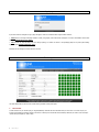
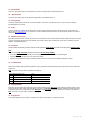
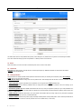
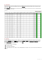
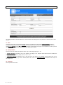
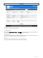
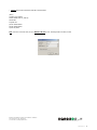
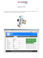
Sigma user manual
Document Rev. 1
Sigma is main (master) controller for tracker network in large scale solar power plant applications. It is directing and supervising up to 64 slave
positioners “Nanos”. User can control whole tracker’s network via integrated web pages.
Sigma user manual_rev1
1
Login page
By the first connection to Sigma’s IP log in page will appear. There are two different kind of logins: Admin and User.
♦ admin account can change everything needed to control, setup, adjust, service the trackers and Sigma. It is owner’s and installer’s account with
full rights. Default password is “admin”.
♦ user accound can only see values, but can’t change anything. It is meant for visitors or non-priviledge people to see power plant tracking
system as demo. Default password is “user”.
Passwords can be changed in accounts.ini file on SD card.
Monitoring tab
This tab is default tab and will be used in normal working condition of solar power plant.
1.
Time and date
Current solar time for your location (see geo. longitude/latitude). Note that this time could differ from your zone time. It is correct only for your
accurate geo longitude. If Sigma has access to NTP server on internet, this time will be set automatically. Otherwise you need to set it manually in
“system” tab (see chapter 32). Date is today.
2
Sigma user manual_rev1
2.
Voltage
Shows the power supply voltage for Sigma. Nanos could have different voltages than Sigma, if different power supplies were used for trackers.
3.
Current
It is sum of all currents from all Nanos (trackers - motors). This is used for monitoring maximum allowed current, which can be set in »controller«
tab. Suitable when there is one power supply for many trackers and has some current limitation. Trackers will be controlled not to exceed a
maximum permited current. Sigma's current is too low and is not included.
4.
Wind speed, solar radiation and temperature
Shows weather data directly from external sensors, if they were in use. Setup can be done in »weather« tab.
5.
Angle A, B
Currently calculated angle of the Sun. Zero degrees mean true South, negative values are East side, positive West side. For one and two axis
trackers.
6.
Destination A, B
Calculated number which is send to tracker's network. It is strongly depended on a geometry in use. Destination has diagnostic purpose.
7.
Operating mode
Informs in which mode Sigma (and trackers) are.
Tracking mode means normal following the Sun. Calculations are proper. If motor does not run and there are no errors, it could be, that Sun is
still not inside the moving range of the tracker geometry (morning, afternoon).
♦
Night mode means that trackers are moved into night position and will not track the Sun, while the Sun is below the horizon. Night mode times
can be set in “Controller” tab (see chapters 13, 14).
♦
Wind mode is automatically entered when there is too high wind outside and tracker needs to be moved into the wind safe position. For this
feature wind sensor must be installed and parameters need to be set (“weather” tab).
♦
8.
Tracker status
Each tracker represent one cube, coloured according to the status of that tracker (to clear status, see chapter 25):
♦
Green: tracker is OK.
♦
Red: tracker has some errors and therefore it is not moving
♦
Grey: there is no response from that tracker. Status can not be read. Communication problem or no power on the tracker.
By clicking on each cube a pop-up window opened showing current values and descrption of the status.
Sigma user manual_rev1
3
Controller tab
Tab is used to setup tracker’s behaviour and geometry. Some settings are very sensitive and wrong values can cause damage of trackers. Press
“save” button after changing to save new parameters. To dischart, browse to some other tab.
9.
Longitude, latitude
Mean your geographical longitude and latitude. They are both important in order to get proper tracking. Negative values mean »West« and
»South«.
10. Anti-shadowing
Applies only to solar plants, where many trackers are mounted close together in the East-West line. In the morning and in the evening even a small
shadow from neighbor panels could dramatically reduce output power of the panel. This effect appears when one cell inside serial chain is in
shadow, causing all cells in serial chain to fail with power. Some panels have bypass diode. Or tracker should move in opposite direction to
eliminate any shadow. And this way our tracker does.
Write panel width into panel width field and distance between trackers (in E - W line) into panel spacing field. If any of those two fields are 0,
function is disabled.
11. Night position A, B
Is the position in degrees where the tracker will park during the night. This is between night mode and day mode time.
12. Reference interval
Motor (actuator) position needs to be sychonized with internal counters inside Nano electronic module. This can be done manually (»trackers« tab)
or automatically by setting reference interval value. Meaning on how many days it will do the sychonization. Synchonization is done at »day mode
time«.
4
Sigma user manual_rev1
13. Day mode time
Is the hour, when tracker starts to track. Before this hour it waits in the night position. Recommended value is 6.
14.
Night mode time
Is the hour, when tracker stops to track and goes to night position. Recommended value is 22.
15. Moving interval
It means at what interval the solar tracker will correct its position to trace the sun. The minimum value is 1 minute, maximum is unlimited.
Recommended value is 5 minutes.
16. Group
How many trackers are controlled with this Sigma. Value can not be changed. Number of trackers is number of licences. Licences needs to be
bought. See www.solar-motors.com for your reference or contact information below this document. This number directly influences on number of
coloured boxes on “monitoring” tab.
17. Maximum output current
Sigma will controll such number of trackers at once until sum of all tracker's currents reaches maximum permited. Suitable when there is one power
supply for many trackers and has some current limitation. This number is setting value, monitoring value can be seen on »Monitoring« tab (see
chapter 3 for additional information).
18. Geometries
Different trackers have different geometries. Geometry includes parameters A1-A6, B1, B2 and number of selected geometry geometry mode.
Note:
♦
In the case of using our tracker, parameters are already set. Do not change anything.
♦
If you have your own tracker, see Geometry document available on our web side. Or contact our technical support.
♦
If Geometry mode is 0, this axis is not in use. Will not be controlled.
♦
Geometry mode parameters are fixed by purchasing conditions. Contact our sales team to add additional geometries or change.
19. Coordinate mode
Means which coordinate system astronomic equations are using. General known is Azimuth-Elevation system (AE), other less know is Polar-Mount
system (PM).
Note: In the case of using our tracker, parameters are already set.
which coordinate system to use
axis
1
AE system
azimuth
2
AE system
elevation
3
PM system
hour angle
4
PM system
polar elevation
20. Moving properties
Each motor uses some moving range measuring impuses by hall incremental encoder. Max range means maximum permited impulses, at which
value motor will stop. Above, motor will be hard stopped . The same is for min range limit. Relation between impulses and degrees (slew drives)
or milimeters (linear motors) is defined by gear ratio. Gear ratio is counted number of impulses by positioner per one degree or one milimeter.
Note: In the case of using our tracker, parameters are already set.
21. U supply factor
Is measuring calibration factor for voltage on “monitoring” tab. We do not encourage you to change these values.
Sigma user manual_rev1
5
Trackers tab
This tab has direct access to each positioner Nano (tracker). Some settings are very sensitive and wrong values can cause damage of trackers.
Press “save” button after changing to save new parameters. To dischart, browse to some other tab.
22. Device
Select which tracker you want to see. Enter a number and press “enter” or click on “send” button.
23. Tracker info
Device ID means which tracker is currently selected - monitored (see chapter 22). Additional information are serial number and software
(firmware) version of selected Nano.
24. Tracker parameters
These parameters are directly important for Nano positioner. Parameters are factory set according to used actuator (motor). Do not change
values unless you are sure what you are doing.
Max and min range limits the moving of the motor at positioner level. These settings should be the same as those on »controller« tab (see
chapter 20).
♦
♦
I motor limitation is maximum permited current in positioner. Do not set greater than 5 Amps (hardware limit).
♦ U I measuring factors are measuring calibration factors for voltage and current measurement in positioner. We do not encourage you to
change these values.
Rest timeout, position A, B. When RS485 communication fails due to any reason, each positioner (tracker) can go to some predefined “rest”
position by itself and so set panels to the best position for catching the Sun as fixed panels (until communication is repaired). Timeout can be set in
seconds, 0 = disabled feature.
♦
Modbus timeout is similar like Rest timeout, but it just indicate communication failure by turning orange LED on (front panel of positioner
Nano). Status can not be seen on the web, if communication fails.
♦
♦ Reference timeout means how long motor is going from totally extended position to totally closed position. This is maximum permited time for
motor to go to the reference. If this time is exceed, reference error is set in tracker status (i.e. free motor).
6
Sigma user manual_rev1
25. Manual mode
Selected tracker can be also manually controlled for the service or installation purpose. Enter impulses number for each axis and press »enter« (or
»send« button). »Stop« button will immeadiatelly stop the moving. »Home A, B« will proceed synchronization for both axis (manual reference –
see also chapter 12).
Button »clear status« will clear any error in the selected Nano positioner (see chapter 8). In the case of any error seen on »monitoring« tab first
remove that error, than clear the status.
26. Monitoring
To overview some important values from all trackers. Similar as on “monitoring” tab, but more detailed. Meant for diagnostic purpose. First few
columns have tracker’s ID, firmware version of the positioner (Nano), voltage and current of the tracker (sum of these currents is shown on
the “monitoring” tab – see chapter 3). Remain A, B is last synchonization misalignment after doing reference A, B. Position A, B is motor
position, destination A, B are last received destination from Sigma. Status of each tracker here is represent as HEX value (advanced
information). See chapter 8 for tracker status.
♦
S = status (green, red, gray – see chapter 8)
♦
M = some motor is moving
♦
H = doing reference (synchonization)
T = tracking enable (green cube) / disable (no cube). Enabling/disabling for all trackers at once can be done with button “Enable all” and
“Disable all”.
♦
Sigma user manual_rev1
7
Weather tab
Tab is holding parameters of external weather sensors. Press “save” button after changing to save new parameters. To dischart, browse to some
other tab.
27. Wind
If the wind is strong enough, it could damage the panels. Therefore it is suitable to move the panels into wind save position (normally in
horizontal position), when wind speed is over threshold. At first exceeding threshold will put panels to position A, B. If the wind is below the
threshold for the fall time, it will turn to normal tracking. Wind sensor should be voltage output type 0-10V (not impulsed nor current loop 4-20mA
type). Koeficient value means sensor output voltage per each 1km/h (sensor constant).
28. Other parameters
Second two sensors are radiation and temperature sensors. They are also voltage output type 0 – 10V.
Radiation koeficient is calculated as: Koef = (max_radiation / max_voltage) * 0.011. Example: if sensor measures from 0 to 1200W/m² and
has range from 0 – 10V, the Koef = (1200W / 10V*m²) * 0.011 = 1.32.
♦
♦ Temperature koeficient is calculated as: Koef = (max_temp_range / max_voltage) * 0.011. Example: if sensor measures from -30ºC to
+70ºC it means that max_temp_range is 100ºC. Therefore (100ºC / 10V) * 0.011 = 0.11. Temperature offset is temperature at 0V on output. In
this example -30ºC.
29. Monitoring
Shows output data of the sensors.
8
Sigma user manual_rev1
System tab
Tab is holding system and network parameters of Sigma. Web access is conditioned by these parameters. Press “save” button after changing to
save new parameters. To dischart, browse to some other tab.
30. Network parameters
Shows currently set IP address, netmask, gateway and MAC address for Sigma. Due to security reason they can not be changed via web
page, but owner can set them directly on SD card (system.ini file). NOTE: Do not change MAC address.
31. Server parameters
These parameters are meant for upgrading. After newer firmware is available from our company, Sigma can automatically download the file and
upgrades itself or positioners (trackers). We do not encourage you to change these values.
32. Clock
Set current clock and date manually. Be careful to enter proper format hhmmss and ddmmyyyy.
Example: 12:23:30 = 12hours 23minutes and 30 seconds = 122330, 16 April 2011 = 16042011
Sigma user manual_rev1
9
About tab
This tab has informations about the owner. Tab is not seen when logged on with user account, only admin can see it. Fields can be changed in file
“about.ini” on SD card.
Micro SD card
There are few important files stored in this Micro SD card. Sigma needs to be powered off before pulling the card out.
♦
System.ini holds Sigma’s network data. Please refer to chapter 30 for additional information. Default values are:
[TCP/IP]
ip_address=192.168.0.10
ip_netmask=255.255.255.0
ip_gateway=192.168.0.1
Note: MAC address needs to be unique. Do not change it.
♦
Accounts.ini holds passwords for login accounts. Please refer to chapter “login page” for additional information. Default values are:
[admin]
admin=admin
[user]
user=user
10
Sigma user manual_rev1
♦
About.ini have owner’s information. Please fill in the informations.
[about]
company=Your Company
address=Middle street 10, 1234 City
latitude=45.0
longitude=15.0
phone1=003861234567
phone2=003861234567
cperson=My Name
Note: in the case of a new SD card, use up to 2GB Micro SD card or lower. Formating needs to be FAT32 / 512kB.
SunTracer® is registred trade m ark of com pany Sat Control. © All rights reserved.
Manufacturer: SAT CONTROL d.o.o. Poženik 10, SI-4207 CERKLJE - SLOVENIA-EU
Phone: +386 4 281 62 00, Fax: +386 4 281 62 12
www.solar-motors.com, mailto:[email protected]
Copying is prohibited. Product is patented and protected by the Copyright Law.
SunTracer is a registered trade mark of the Sat Control © company. All rights reserved.
Sigma user manual_rev1
11