1
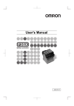
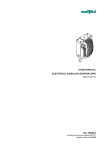
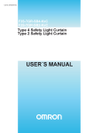
USER'S MANUAL
Thank you for purchasing F3SP-B1P Control Unit.
Please read and understand this manual before using the products.
Keep this manual ready to use whenever needed.
Only qualified person trained in professional electrical technique should handle F3SP-B1P.
Since this instruction sheet only provides general infomation, refer to the instruction
manual of the sensor.
Please consult your OMRON representative if you have any questions or comments.
Jul. 2011
EC Declaration of Conformity
OMRON declares that Type F3SP-B1P is in conformity with the requirements of
the following EC Directives:
- EMC Directive: 2004/108/EC
- Machinery Directive: 2006/42/EC
Standards
The F3SP-B1P received the following approvals in combination with the
F3SN/F3SH/F3SR/F3SJ:
・ From EU accredited body TUV-SUD Product Service GmbH:
- EC Type-examination in accordance with the EU Machinery Directive
Approved standards: EN61496-1, CLC/TS 61496-2 (IEC61496-2)
・ From the Third Party Assessment Body UL:
- UL Listed to U.S. and Canadian safety standards
Approved standards: IEC61496-1, IEC61496-2,
UL508, CAN/CSA C22.2 No.14, CAN/CSA C22.2 No.8
Precaution for Safe Use
Meanings of Signal Words
The following signal words are used in this manual.
Indicates a potentially hazardous situation which, if not avoided,
will result in minor or moderate injury, or may
WARNING
result in serious injury or death.
Additionally there may be significant property damage.
24VDC
13
NC
Input power
indicator
Relay operation
indicators
No.
23
NC
PWR
33
L1
41
H1
H1
X1
J1
A1
Power input
terminal
INTERLOCK
OSSD1
EMITTER
K1
OSSD2
PE
Vibration resistance
T31
Ambient temperature
Ambient humidity
14 24 34 42
P1
Insulation resistance
PLC
Dielectric strength
● Wiring when the EDM is not used.
13 23 33 41
13 23 33 41 H1 J1
NC NC L1 H1 X1 A1
NC
24
T31
34
T32
42
PE
NC
A2
P1
Power input
terminal
I/O terminals
Earth terminal
Output terminals
I/O terminal
INTERLOCK
2
6
J1
T31
T32
OSSD 2
Emitter
Interlock selection input
(* Function select input)
2
3
4
+24V
OSSD 1
Auxiliary output
+24V
Test input
Reset input
Receiver
KM2
K1 and K2 LED
do not turn on.
*S3 If the switch is not necessary,
connect between X1 and H1.
M
S1: External test switch
S2: Interlock / Lockout reset switch
S3: Lockout reset switch
KM1,KM2: Magnet contactor
M: 3-phase motor
K1 or K2 LED
does not turn on.
5-2 When in combination with the F3SR
● Wiring for Manual reset mode and the EDM function enabled
Power LED
does not turn on.
(* Operating range select input)
4
Precautions for Safe Use
RS-485 ( A)
5 RS-485 (A)
RS-485 ( B )
6 RS-485 ( B )
0V
7 0V
8 EDM input
NC
*Names used when connecting with the F3SR
S1
S2
3
5
A1
OSSD 1
Receiver
J1
H1
X1
OSSD 2
P1
13
23
33
41
RESET Operating
range
select input
KM1
K1
KM2
K2
Two,4.2 dia. or M4
Emitter
K1
PE
T31
24
34
42
F3SP-B1P
KM1
KM1
24VDC
E1
KM2
KM2
10.5
24-M3
4.6 dia.
● Wiring when the EDM is not used.
● Wiring for Auto-reset mode.
35±0.3
EDM
Mounting holes
S1
7×5=35
13 MAX.
J1
H1
9
R2.3
S1
T31
H1
L1
Function
select input
J1
H1
X1
KM1
KM2
TEST
Check the wiring to External input.
(input line)
Check the Sensor.
Replace with a new External devices.
(Contactor etc)
Replace with a new product.
Check the wiring to External input.
(input line)
Check the Sensor.
Replace with a new product.
Check the wiring to External input.
(input line/power line)
Check the supply voltage to
Expansion.
Check the wiring to External input.
(output line)
Replace with a new Protective device.
(Fuse etc)
M
OMRON shall not be responsible for conformity with any standards, codes, or
regulations that apply to the combination of the products in the customer's
application or use of the product.
Take all necessary steps to determine the suitability of the product for the
systems, machines, and equipment with which it will be used. Know and
observe all prohibitions of use applicable to this product.
NEVER USE THE PRODUCTS FOR AN APPLICATION INVOLVING SERIOUS RISK
TO LIFE OR PROPERTY WITHOUT ENSURING THAT THE SYSTEM AS A WHOLE
HAS BEEN DESIGNED TO ADDRESS THE RISKS, AND THAT THE OMRON
PRODUCT IS PROPERLY RATED AND INSTALLED FOR THE INTENDED USE
WITHIN THE OVERALL EQUIPMENT OR SYSTEM.
OMRON EUROPE B.V. (Representative in EU)
● Wiring when the EDM is used.
EDM
111 MAX.
3 For safety category and PL
The F3SP-B1P can construct the condition conforming to cat. 4 / PLe or cat.2 / PLc requested by EN
ISO13849-1 with combination as follows:
- Category 4 / PLe:
Type F3SN-A□□□□P□□ or F3SH-A09P03 or F3SR-430B□□□□
or F3SJ-A□□□□P□□ or F3SJ-B□□□□P25
- Category 2 / PLc:
Type F3SN-B□□□□P□□
Note: Category is not judeged only by the condition above, but is judged by the
condition of the whole control system.
- In order to be cat. 4/ PLe, or cat. 2/ PLc
1. The NC contact from a contactor is required to feed back signal.
(Refer to the application examples. For category 2, it is not mandatory.)
2. PE terminal should be connected to protective earth.
3. In application with long term operation of devices, the F3SP-B1P must have cyclic
operation every 24 hours at least in order to detect failures and a failure
accumulation.
Failures of the Sensor.
Failures of the parts of the
External devices. (Contactor etc)
Failures of the parts
of the internal circuits.
Failures involving the wiring
of External input. (input line)
Failures of the Sensor.
Failures of the parts
of the internal circuits.
Failures involving the wiring
of External input.
(input line / power line)
Supply voltage outside
the rated value.
Failures involving the wiring
of External input. (output line)
Failures of the parts of the
Protective device. (Fuse etc)
Shiokoji Horikawa, Shimogyo-ku, Kyoto, 600-8530
JAPAN
5
RESET
S1: External test/Lockout reset switch
S2: Interlock reset switch
KM1,KM2: Magnet contactor
M: 3-phase motor
E1: 24 VDC power supply (S82K)
2,500VAC 1min.
Replace with a new product.
OMRON Corporation
RESET
● Wiring for Auto-reset mode.
45 MAX.
All LED turn on.
but the safety
output doesn't on.
Failures of the parts
of the internal circuits.
Failures involving the wiring
of External input. (input line)
T32
X1
5.6
63
L1
Function
TEST
select input
43
76 MAX.
9
T31
H1
100Mohm MIN.
(by 500VDC Megger)
Suitability for Use
14
T32
T32
3
2
100,000 operations MIN. Rated load
Switching frequency 1,800 operations/h
5,000,000 operations MIN.
Switching frequency 18,000 operations/h
EDM
0V
5.9
Between inputs and outputs
Between different poles of output
Between inputs and outputs
Between different poles of output
K2
Emitter
A2
91
L1
Function
TEST
select input
2 External Physical Dimensions
Receiver
H1
External
Internal
Type F3SP-B1P can detect the failure for the safety of internal circuit, parts condition and
external wiring.
Failure indication
Checking points and measures
Failure condition
by LED
to take
TEST
RESET
1
IP40
● Pollution degree
7 Failure detection
X1
H1
NC NC T31 T32 PE A2
Signal Name
Pin
No.
1
L1
Mechanical endurance
KM1
SAFETY LIGHT CURTAIN
CONTROL UNIT
NC
14
H1
IP20
● Life expectancy
Electrical endurance
S3
Terminals
Enclosure
● Isolation specification
KM2
S1
Type F3SP-B1P
Destruction: 300 m/s2
Malfunction: 100 m/s2
-10 to 55 ℃
35 to 85%RH
Shock resistance
T32
25VAC 5A cosφ=1 30VDC 5A L/R=0ms
5A
25VAC 60VDC
AC: 125VA DC: 150W
● Protection class
AUXILIARY
K2
EDM
A2
TYPE F3SP-B1P
24VDC
-15% to +10% of rated supply voltage
1.7W MAX. (Exclude sensor power)
250VAC 5A cosφ=1 30VDC 5A L/R=0ms
5A
250VAC 125VDC
AC: 1250VA DC: 150W
100ms MAX.
(exclude sensor response time)
10ms MAX.
(exclude sensor response time)
10 to 55Hz 0.35mm single amplitude
(0.7mm double amplitude)
K1
K2
14 24 34 42
F3SP-B1P 24 VDC
Max. switching capacity
Rated load
Rated carry current
Max. switching voltage
Max. switching capacity
Response time
KM2
K1
WARNING
(1) For malfunctions in case that the power supply picks up gradually.
Malfunctions in case that the power supply picks up gradually. In case that the input circuits
close before the power supplies, internal logic may malfunction.
(2) Handling
Do not drop the F3SP-B1P or shock or vibrate the F3SP-B1P excessively. Doing so may result
in damage to the F3SP-B1P or cause F3SP-B1P to malfunction.
(3) For adhesion of solvent
Adhesion of solvent, likely Alcohol, Thinner, Trichloroethane, Gasoline, on the product should
be prohibited. Such solvent cause erasing the marking and being inferior of the parts.
(4) Take appropriate and sufficient countermeasures when installing systems in the following
locations. Inappropriate and insufficient measures may result in malfunction.
1. Locations subject to static electricity or other forms of noise.
2. Locations subject to possible exposure to radioactivity.
3. Locations close to power supplies.
(5) Wiring
1. Use the following to wire the F3SP-B1P.
- Stranded wire (Flexible wire): 0.75 to 1.5mm2
- Solid wire: 1.0 to 1.5mm2
2. The F3SP-B1P may malfunction or generate heat.
- Tighten each screw to a torque of 0.78 to 1.18N・m
3. PE is a ground terminal. When machine is grounded at the positive, the PE terminal
should not be grounded.
4. NC terminals do not have any function. Do not wire them.
RECEIVER
RESET
*S1 Open: Normal light emission.
Close: Stop light emission.
K2
Rated carry current
Max. switching voltage
Operation time
● Wiring for Auto-reset mode.
I/O terminals
Operating voltage range
Rated power consumption
Rated load
● Characteristics
13 23 33 41
X1
I/O terminals
Output terminals
8
Precautions for Correct Use
H1
J1
KM1
7
(1) When ready for wiring, the power source should be disconnected first. Further, at operating
this unit, the terminal cover should be closed correctly in orde to prevent an electrical shock.
(2) Do not wire in case threat of Lightning. otherwise an electric shock may occur.
(3) Do not apply any excessive voltage or current to the input or output circuit the F3SP-B1P.
Doing so may result in damage to the F3SP-B1P or cause afire.
(4) Do not apply any variable voltage, otherwise F3SP-B1P may malfunction.
(5) Do not connect any overload to the output circuit, otherwise the F3SP-B1P in operation will
generate excessive heat and the output elements of the F3SP-B1P may short-circuit or fire
may result.
(6) The lifetime of F3SP-B1P depends on the conditions of switching of its outputs. Be sure to
conduct its test operation under actual operating conditions in advance and use it within
appropriate switching cycles. Change the F3SP-B1P before expected operation. Over
operation may cause may short-circuit or may malfunction.
(7) Do not operate the F3SP-B1P with flammable or explosive gass. An arc with operation and
the heat of relay will cause a fire or an explosion.
(8) Do not disassemble, repair, or modify the F3SP-B1P, otherwise an electric shock may occur or
the F3SP-B1P may malfunction.
(9) Use protective device (Fuse etc) for short-circuit protection and ground fault protection,
otherwise a fire may occur or the F3SP-B1P may malfunction.
(10) Be sure to wire correctly. The sensor connector is the same both the emitter and the
receiver.
(11) Do not dismantle, repair, or modify F3SP-B1P. it may lead to loss of its safety functions.
L1
Rated supply voltage
TEST
Sensor connectors For Receiver(Black)
For Emitter(Gray)
Indicates mandatory actions
Serious injury may possibly occur due to loss of required safety functions.
Wire F3SP-B1P properly so that supply voltages or voltages for loads do
NOT touch the safety inputs accidentally or unintentionally.
S2
H1
A1
1 Designation
● Connector
Serious injury may possibly occur due to breakdown of safety outputs.
Do not connect loads beyond the rated value tothe safety outputs.
S1
KM1
● Unit
Alert Statements
Input
● Wiring for the Manual reset mode and the EDM function.
14 24 34 42 NC P1
Meaning of Alert Symbols
The following alert symbols are used in this manual.
Indicates prohibited actions
5 Application examples
5-1 When in combination with the F3SN/F3SH/F3SJ
84 ±0.3
English
● Ratings
For North
America
Control Unit
For F3SN-A □□□□P□□, F3SN-B □□P□□, F3SH-A09P03,
F3SR-430B □□□□, F3SJ-A □□□□P□□, F3SJ-B □□□□P25
The following functions of the sensor can be used. Refer to the instruction manual of
the sensor for detailed information.
・Auto reset/Manual reset (Interlock function)
・External device monitoring (EDM)
・External test (Light emission stop function by test input)
・Auxiliary output (PNP transistor output) (*)
*When in combination with the F3SR, "auxiliary output" can not be used.
Output
Type F3SP-B1P
6 Specifications
4 Functions
(6) Mounting multiple units
When mounting multiple units close to each other, the rated current will be 3A.
Do not apply a current higher than 3A.
(7) Operating and Storage Environment
Do not operate or store the F3SP-B1P under the following conditions.
Doing so may result in damage to the F3SP-B1P or cause the F3SP-B1P to malfunction.
1. The places with direct sunlight.
2. The places with ambient temperature ranges not within -25 to 55℃.
3. The places with rapid temperature changes resulting in condensation or relative humidity
ranges not within 35 to 85%RH.
4. The places with atmospheric pressure out of the range 86 to 106kpa.
5. The places with corrosive or inflammable gas.
6. The places with water, oil, or chemical sprayed on the F3SP-B1P.
7. The places with vibration or shock affecting the F3SP-B1P.
8. The places with atmosphere containing dusts, saline or metal powder.
(8) DC power supply units
In order to conform to IEC61496-1 and UL508, DC power supply unit must satisfy all the
conditions mentioned in the instruction manual the sensor.
(9) Installation
1. Cabinet of F3SP-B1P should meet IP54 protection.
2. The F3SP-B1P is exclusively for F3SN-A□□□□P□□ , F3SN-B□□□□P□□,
F3SH-A09P03, F3SR-430B□□□□, F3SJ-A□□□□P□□, F3SJ-B□□□□P25 series.
3. The following functions are set with two short pieces when delivered. Change wirings
depending on necessary functions.
- H1-X1 short: Auto reset mode.
- T31-T32 short: EDM function is inactive.
*These combinations of wiring and function are for the use with the F3SN/F3SH or F3SJ.
When in combination with the F3SR, refer to Section 5.
(10) For feedback purpose use devices with contacts capable of switching micro loads of
24VDC, 5mA.
(11) This is a class A product. In residential areas it may cause radio interference, in which case
the user may be required to take adequate measures to reduce interference.
For Europe
Original instructions
Wegalaan 67-69, NL-2132 JD Hoofddorp
THE NETHERLANDS
PHONE 31-2356-81-300 FAX 31-2356-81-388
OMRON SCIENTIFIC TECHNOLOGIES INC.
6550 Dumbarton Circle, Fremont CA 94555-3605
U.S.A
PHONE 1-510-608-3400 FAX 1-510-744-1442
OMRON ASIA PACIFIC PTE. LTD.
438A Alexandra Road # 05-05/08,
Alexandra Technopark Singapore 119967
SINGAPORE
PHONE 65-6-835-3011 FAX 65-6-835-2711
OMRON (CHINA) CO., LTD.
Room 2211, Bank of China Tower, 200 Yin Cheng Zhong Road,
PuDong New Area, Shanghai, 200120, China
PHONE 86-21-5037-2222 / FAX 86-21-5037-2200
Note: Specifications subject to change without notice.
OMRON AUTOMATION AND SAFETY • THE AMERICAS HEADQUARTERS • Chicago, IL USA • 847.843.7900 • 800.556.6766 • www.omron247.com
OMRON CANADA, INC. • HEAD OFFICE
Toronto, ON, Canada • 416.286.6465 • 866.986.6766 • www.omron247.com
OMRON ARGENTINA • SALES OFFICE
Cono Sur • 54.11.4783.5300
OMRON ELECTRONICS DE MEXICO • HEAD OFFICE
México DF • 52.55.59.01.43.00 • 01-800-226-6766 • [email protected]
OMRON CHILE • SALES OFFICE
Santiago • 56.9.9917.3920
OMRON ELECTRONICS DE MEXICO • SALES OFFICE
Apodaca, N.L. • 52.81.11.56.99.20 • 01-800-226-6766 • [email protected]
OTHER OMRON LATIN AMERICA SALES
54.11.4783.5300
OMRON ELETRÔNICA DO BRASIL LTDA • HEAD OFFICE
São Paulo, SP, Brasil • 55.11.2101.6300 • www.omron.com.br
OMRON EUROPE B.V. • Wegalaan 67-69, NL-2132 JD, Hoofddorp, The Netherlands. • +31 (0) 23 568 13 00 • www.industrial.omron.eu
Authorized Distributor:
Automation Control Systems
• Machine Automation Controllers (MAC) • Programmable Controllers (PLC)
• Operator interfaces (HMI) • Distributed I/O • Software
Drives & Motion Controls
• Servo & AC Drives • Motion Controllers & Encoders
Temperature & Process Controllers
• Single and Multi-loop Controllers
Sensors & Vision
• Proximity Sensors • Photoelectric Sensors • Fiber-Optic Sensors
• Amplified Photomicrosensors • Measurement Sensors
• Ultrasonic Sensors • Vision Sensors
Industrial Components
• RFID/Code Readers • Relays • Pushbuttons & Indicators
• Limit and Basic Switches • Timers • Counters • Metering Devices
• Power Supplies
Safety
• Laser Scanners • Safety Mats • Edges and Bumpers • Programmable Safety
Controllers • Light Curtains • Safety Relays • Safety Interlock Switches
F57I-E-01
06/12
Note: Specifications are subject to change.
Printed on recycled paper.
© 2014 Omron Electronics LLC
Printed in U.S.A.