1
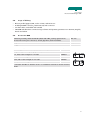
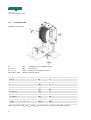
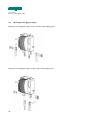
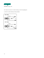
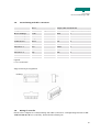
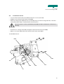
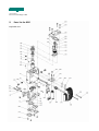
USER MANUAL
ELECTRICAL PARALLEL GRIPPER GPE
Mechanical Part
BA-100069
Starting from serial number 427127
English, edition 02/2008
User manual
Electrical Parallel Gripper GPE
Contents
1.
Important information ____________________________________________________________ 2
1.1.
Introduction ______________________________________________________________________ 2
1.2.
EU - conformance (to EU Directive on Machines, Appendix II A) ________________________ 2
1.3.
Product description and application _________________________________________________ 2
1.4.
Dangers _________________________________________________________________________ 2
1.5.
Additional information_____________________________________________________________ 3
1.6.
Validity of the User Manual_________________________________________________________ 3
2.
Technical Data ___________________________________________________________________ 4
2.1.
GPE Technical Data _______________________________________________________________ 4
2.2.
GPE Gripping force diagram with Speed > 50% ______________________________________ 5
2.3.
GPE Opening and closing times ____________________________________________________ 5
2.4.
Dimensions GPE __________________________________________________________________ 6
2.5.
Scope of delivery _________________________________________________________________ 7
2.6.
Accessories GPE __________________________________________________________________ 7
2.7.
Permissible loads _________________________________________________________________ 8
3.
Commissioning __________________________________________________________________ 9
3.1.
Installation position and assembly___________________________________________________ 9
3.2.
Mounting of the gripper fingers ___________________________________________________ 10
3.3.
Installation and connection of the inductive proximity switches ________________________ 11
3.4.
Internal wiring and cable connections ______________________________________________ 13
3.5.
Wiring of controller ______________________________________________________________ 13
4.
Maintenance____________________________________________________________________ 14
4.1.
Lubrication ______________________________________________________________________ 14
4.2.
Replacement of the motor ________________________________________________________ 16
4.3.
Toothed belt tension _____________________________________________________________ 17
5.
Parts list for GPE _______________________________________________________________ 18
6.
General information _____________________________________________________________ 21
6.1.
Environmental compatibility and disposal ___________________________________________ 21
1
User manual
Electrical Parallel Gripper GPE
1.
1.1.
Important information
Introduction
This User Manual describes the mechanical design, the technical data, the load limits, installation,
maintenance and spare parts of the electrical parallel gripper GPE.
1.2.
EU - conformance (to EU Directive on Machines, Appendix II A)
Rules and standards complied with:
Machinery guidelines 89/392/EEC, 91/368/EEC
Manufacturer:
Montech AG, Gewerbestrasse 12 CH–4552 Derendingen
Tel. +41 32 681 55 00, Fax +41 32 682 19 77
1.3.
Product description and application
Electrical parallel grippers GPE are electrically operated, moment-controlled grippers for internal
and external gripping of parts. They are used wherever workpieces have to be regularly clamped for
workpiece transport (handling).
The load limits which were specified by the technical data must be complied with in all
circumstances. Overloading can lead to faults and failure of the devices.
1.4.
Dangers
The use of electrical parallel grippers GPE in an installation is only permissible when they are
guarded by movable, isolating protective devices as per EN 292-2, para.4.2.2.3. Failure to comply
with this protective measure can result in injury due to fingers being squeezed or knocked,
particularly in machines which start up automatically.
It is essential to comply with the operating conditions and safety instructions described in the
controller User Manual. It is essential to comply with the stated load limits.
– During operation, the surface of the motor may reach up to 100°C. The motor must
not be touched if the temperature has exceeded 40°C (measurement of the surface
temperature).
– During maintenance work on the GPE, it must be ensured that the drive energy has
been switched off and cannot be switched on by unauthorized persons.
2
User manual
Electrical Parallel Gripper GPE
1.5.
Additional information
The aim of the present User Manual is to enable users to employ electrical parallel grippers GPE
correctly and safely. Should further information be required in relation to your particular application,
please contact the manufacturer.
When reordering User Manuals, it is essential to quote the reference number, the product name and
serial number.
This document can be obtained from our homepage www.montech.com.
Nameplate
Reference number
Product name
Serial number
Montech AG
Management
U. D. Wagner
C. Wullschleger
1.6.
Validity of the User Manual
Our products are continually updated to reflect the latest state of the art and practical experience.
In line with product developments, our User Manuals are continually updated.
Every User Manual has an article number e.g. BA-100069 and an edition number (e.g. 02/2008).
The article number and the date of edition are evident on the title page.
Validity
Main device:
Full name
Short name
Reference number
Electrical Parallel Gripper GPE
GPE
57833
3
User manual
Electrical Parallel Gripper GPE
2.
Technical Data
2.1.
GPE Technical Data
Stroke = Total travel of jaws
[mm]
12
Opening/closing time
[s]
See diagram
Weight
[kg]
0.91
Mass moment of inertia JZ
[kgcm2]
5.9
Max. cycles per minute
80
Drive
Brushless electronic commutated DC
motor, toothed belt and ballscrew
Hall sensor resolution
1)
Rated motor power
[mm]
0.263
[W]
25
IP42
Protection type
Repeatability
2)
Check on end position open/closed
3)
[mm]
inductive proximity switches
Supply voltage/current
Ambient
Temperature
±0.05
24VDC / 1.5A
[°C]
10…50
Rel. humidity
5%-85% (without condensation)
Purity of the air
Normal workshop atmosphere
Warranty period
2 years from the date of delivery
Mounting position
any
Material
Aluminum, steel, bronze, plastic
1)
Stroke of the jaws per signal combination (with evaluation of the 6 hall sensor signal
combinations per motor revolution)
2)
Scatter of the clamped end position, measured for 100 successive strokes at constant
motor temperature
3)
See accessories
4
User manual
Electrical Parallel Gripper GPE
2.2.
GPE Gripping force diagram with Speed > 50%
Current [%]
Fs: Gripping force per gripping finger [N]
Important:
The gripping force is influenced by the
deformation of the application-specific
gripping fingers!
2.3.
GPE Opening and closing times
Speed [%]
Current [%]
t: Opening/closing times from
edge change at the input
"Direction“[s]
t [s]
5
User manual
Electrical Parallel Gripper GPE
2.4.
Dimensions GPE
Thread
Bores
Reference number
GPE
6
57833
Thread
Bores
Ø6.5mm bores for
proximity switch
User manual
Electrical Parallel Gripper GPE
2.5.
–
–
–
–
Scope of delivery
Electric parallel gripper GPE, stroke 12 mm, with EC motor
Including ECMR controller, parameterised, with connector
3 m data cable, unshielded and towable
CD-ROM with Windows commissioning software and Operating Instructions in German, English,
French and Italian.
2.6.
Accessories GPE
Inductive proximity switches PNP Ø 6,5mm with LED, security against shortcircuit and reverse pin connection, switch gap 2mm, flush-mountable:
Ref. No.
length 2m
508842
pluggable M8x1
508843
Connecting cable
504610
5 m, with socket angled on one side
504929
10 m, with socket straight on one side
507528
10 m, with socket angled on one side
507529
1)
especially suitable for dynamic stress, for example movement in energy carrying
chains.
Ø5
5 m, with socket straight on one side
L
30.5
L
26.5
Ø5
for proximity switch 3-pin, highly flexible, screwable M8x1
Ref. No.
1)
7
User manual
Electrical Parallel Gripper GPE
2.7.
Permissible loads
Definition of the loads
Fs
Foy , Foz
Lx , Ly , Lz
Mox , Moy , Moz
[N]
[N]
[mm]
[Nmm]
Clamping force per gripper finger
Static forces
Distances over which force acts
Static moments
Fs
[N]
See clamping force diagram
Foy zul.
[N]
75
Foz zul.
[N]
80
Lx zul.
[mm]
80
Ly zul.
[mm]
80
Lz zul.
[mm]
100
(Lx + Ly) zul.
[mm]
80
(Ly + Lz) zul.
[mm]
100
(Lz + Lx) zul.
[mm]
100
Mox zul. = Foy • Lz + Foz • Ly
[Nmm]
1500
Moy zul. = Fs • Lz + Foz • Lx
[Nmm]
6000
Moz zul. = Fs • Ly + Foy • Lx
[Nmm]
4000
With cooperation of Mox, Moy, and Moz any moment may reach its permissible maximum.
8
User manual
Electrical Parallel Gripper GPE
3.
3.1.
Commissioning
Installation position and assembly
Electrical parallel grippers GPE can be installed in any position.
The GPE is assembled by means of Quick Set fixing elements (SLL-20-40, SLL-55-40 or SLR-15-40) on
the dovetail of the cover (item 260) or via threaded or positioning holes in the cover (item 260).
Assembly with Quick-Set fixing elements
GPE with SLL-20-40, SLL-55-40, SLR-15-40
260
Assembly via threaded and positioning holes
GPE with screws and pins
260
9
User manual
Electrical Parallel Gripper GPE
3.2.
Mounting of the gripper fingers
Mounting of the gripper fingers on the outside of the gripping jaws
Mounting of the gripper fingers on the inside of the gripping jaws
10
User manual
Electrical Parallel Gripper GPE
3.3.
Installation and connection of the inductive proximity switches
The inductive proximity switches to be installed must fulfill the following conditions:
Switch gap:
Flush-mountable
Housing diameter:
Minimum housing length (Ø6.5):
2mm
6.5mm
27mm
The proximity switches are mounted by removing the respective closure screw (item 280b), screwing
the supplied sensor fixing nut (item 540) into the housing (item 10) and pushing the proximity switch
until it stops in the bottom of the hole in the housing (item 10). Fixing is carried out by tightening
the sensor fixing nut (item (540).
Installation of the inductive proximity switches
280b
Proximity switch
pos. closed
Proximity switch
pos. open
540
540
Polling of the clamping position:
In order to ensure polling of the clamping position via the inductive proximity switches,
the gripper fingers must be designed so that the clamping position is in the region of
an end position of the gripping jaw ( < 1 mm before the nominal stroke end).
Connecting cable to proximity switch:
To ensure that the forces can never act on the proximity switches, the connecting
cables should always be provided with tension reliefs!
11
User manual
Electrical Parallel Gripper GPE
The electrical connection is made according to the following diagram:
Connection of the inductive proximity switches
DC voltage
brown
black
blue
DC voltage
brown
black
blue
12
User manual
Electrical Parallel Gripper GPE
3.4.
Internal wiring and cable connections
Output cable 10 x 0.25 mm2
Motor
Designation
Wire color
Plug connector
Wire color
Plug connector (item 530)
Motor winding 1
brown
1
white
1
Motor winding 2
red
2
brown
2
Motor winding 3
orange
3
green
3
U Hall sensors
yellow
4
red
4
GND Hall sensors
green
5
blue
5
Hall sensor 1
blue
6
yellow
6
Hall sensor 2
violet
7
grey
7
Hall sensor 3
grey
8
pink
8
-
-
-
black
n.c.
-
-
-
violet
n.c.
Legend:
n.c.not connected
Plug connector pin assignment
marking
3.5.
Wiring of controller
Please refer to Chapter 3.4 "Internal wiring and cable connections" and Operating Instructions BA100078 ECMR (EC Motor Controller), electrical and software part.
13
User manual
Electrical Parallel Gripper GPE
4.
4.1.
Maintenance
Lubrication
During maintenance work on the GPE, it must be ensured that the drive energy is
switched off and cannot be switched on by unauthorized persons.
It is essential to use only Klüber oil “Paraliq P460“ (Montech Ref. No. 504721) as lubricant.
Lubrication interval: 800 operating hours
Lubrication of ballscrew:
– Loosen cheese head screws (item 480) and remove cover (item 340).
– Move gripping jaws (item 30) to approx. 2 mm before opened end position.
– Apply a few drops of lubricant to the ballscrew (item 80) through the lubricating opening in the
housing (item 10). Close and open gripping jaws (item 30) several times. Repeat process 3-4
times.
– Invert cover (item 340) over motor (item 330) and double pin housing (item 520) and fix with
cheese head screws (item 480).
Lubrication of ballscrew
330
520
Lubricating opening
10
480
14
340
30
User manual
Electrical Parallel Gripper GPE
In applications with more than 60 cycles/minute, it is advisable additionally to lubricate the guide
rollers (item 70) and the rollers (item 40) at the same time:
– Loosen cheese head screws (item 470) and remove cover plate (item 310).
– Remove both apron plates (item 300).
– Close gripping jaws (item 30) and apply a few drops of lubricant to the guide rollers (item 70).
– Open gripping jaws (item 30) and apply a few drops of lubricant to the rollers (item 40).
– Mount both apron plates (item 300) and fix cover plate (item 310) with cheese head screws
(item 470).
Lubrication of guide rollers
40
70
30
300
40
310
70
470
Lubricate item 40
Lubricate item 70
15
User manual
Electrical Parallel Gripper GPE
4.2.
–
–
–
–
–
–
–
–
Replacement of the motor
Loosen cheese head screws (item 480) and remove cover (item 340).
Pull motor plug connector out of double pin housing (item 520).
Loosen the cheese head screws (item 460) and remove motor (item 330).
Push new motor (item 330) into motor flange (item 240) and push the toothed belt (item 250)
over the toothed wheel on the motor (item 330) by tilting the motor (item 330).
Bring motor (item 330) into a position parallel to the housing (item 10) and fix with the cheese
head screws (item 460) to the motor flange (item 240) (note position of cable exit!)
Check toothed belt tension and set the correct tension according to section entitled “Toothed
belt tension” if the tension is too low.
Insert motor plug connecter on the double pin housing (item 520). Note: loop the cable so that
the cable cannot make contact with the projecting motor shaft when the cover (item 340) is
mounted.
Invert cover (item 340) over motor (item 330) and double pin housing (item 520) and fix the
cheese head screws (item 480).
Installation of motor
480
340
Cable exit (note
position!!)
520
330
460
10
240
250
16
User manual
Electrical Parallel Gripper GPE
4.3.
Toothed belt tension
– Loosen cheese head screws (item 430a) and remove cover (item 260).
– Slightly loosen cheese head screws (item 430b).
– Pull motor flange (item 240) with motor (item 330) away from the housing (item 10) so that the
toothed belt (item 250) is stretched without initial tension.
Excessive tension of the toothed belt (item 250) can lead to destruction of the motor
bearing!
– Hold the motor flange (item 240) and tighten cheese head screws (item 430b).
– Mount cover (item 260) and fix with cheese head screws (item 430a).
Toothed belt tension
430b
430a
330
240
250
260
10
17
User manual
Electrical Parallel Gripper GPE
5.
Parts list for GPE
Exploded view
18
User manual
Electrical Parallel Gripper GPE
Item
Sym. Designation
Ref. No.
◘
Electrical Parallel Gripper GPE
57833
Material
10
◊
Casing
57397
Aluminum
20
◊
Roller holder
57387
Steel
30
◊
Gripping jaw
56377
Steel
40
◊
Roller
56385
Steel
50
◊
Straight pin
502027
Steel
60
◊
Damper
57392
Steel
70
◊
Guide roller
46289
Steel
80
◊
Ballscrew
56646
Steel/diverse
90
◊
Circlip
520045
Steel
100
◊
Adjusting disk
56645
Steel
110
◊
Support ring
57092
Steel
120
◊
Bearing bush
57177
Steel
130
◊
Deep-groove ball bearing
505244
Steel
140
◊
Hexagon nut M7 x 0.75
57389
Steel
150
◊
Bearing cover
57179
Aluminum
160
◊
Toothed wheel
56649
Aluminum/steel
170
◊
Clamping bushing
510010
Steel
180
◊
Centering sleeve
56405
Steel
190
◊
Hexagon nut M6 x 0.75
520042
Steel
200
◊
Deep-groove ball bearing
508279
Steel
210
◊
Guide peg
56644
Bronze
240
◊
Motor flange
56659
Aluminum
250
●
Toothed belt
520079
PU
260
◊
Cover
56386
Aluminum
270
◊
Buffer
57394
PU
280
◊
Closure screw
56660
Steel
300
◊
Apron plate
56388
POM
310
◊
Cover plate
56387
Steel
330
●
Motor with toothed wheel
57528
Various
340
◊
Cover
57464
ABS
400
◊
Straight pin Ø3h6 x 8
502021
Steel
19
User manual
Electrical Parallel Gripper GPE
Item
Sym. Designation
Ref. No.
Material
410
◊
Cylinder head screw M3 x 6
520043
Steel
420
◊
Straight pin Ø4h6 x 30
502043
Steel
430
◊
Cylinder head screw M3 x 10
502503
Steel
440
◊
Cylinder head screw M3 x 8
508470
Steel
460
◊
Cylinder head screw M2 x 5
520053
Steel
470
◊
Cylinder head screw nK M3 x 6
520040
Steel
480
◊
Cylinder head screw M3 x 30
506035
Steel
500
◊
Cable screw union
520197
Brass
510
◊
Cable
520332
Various
520
◊
Double pin housing
520304
Various
530
◊
Plug connector
520303
Various
540
◊
Sensor fixing nut
507399
Brass
550
◊
Ribbed washer M3
505385
Steel
900
◊
Nameplate
41620
Polyester
910
◊
Clear cover
48508
PU
●
EC Motor Controller (ECMR)
57332
Various
● These are wearing parts and are available from stock
◊ Not available ex stock individually (upon request)
◘ Price-listed items available ex stock
20
User manual
Electrical Parallel Gripper GPE
6.
6.1.
General information
Environmental compatibility and disposal
Materials used:
– Aluminum
– Steel
– Bronze
– ABS (acrylonitrile-butadiene-styrene)
– PU (polyurethane)
– POM (polyoxymethylene)
– Brass
– Polyester
Surface treatment:
– Anodization of aluminum
– Coating of plastic
Shaping processes:
– Machining of aluminum, bronze and steel
– Injection molding of plastics
– Extrusion of PU
Emissions during operation:
None
Disposal:
Electrical parallel grippers GPE which cannot be used any more should be recycled, not as complete
units, but dismantled to components and disposed of according to the type of material. The kind of
material used for each part is shown in the spare parts lists. Material which cannot be recycled
should be appropriately disposed of.
21
MONTECH AG
Gewerbestrasse 12, CH-4552 Derendingen
Fon +41 32 681 55 00, Fax +41 32 682 19 77
[email protected], www.montech.com