1
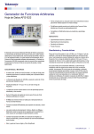
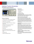
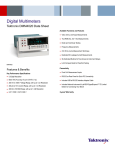
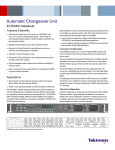
Arbitrary Function Generator
AFG1000 Series Datasheet
Compact form factor for stacking on other bench instruments to save
valuable bench space
Free ArbExpress makes user defined waveforms editing extremely
easy
Compatible with TekSmartLab™ for easy teaching and learning
Standard 5-year warranty
Applications
Electric and electronics experiments
Communications experiments
Sensor simulation
Functional test
The AFG1000 Series Arbitrary Function Generator provides a waveform
generation tool with the best price performance ratio. It includes dual
channel, up to 60 MHz bandwidth and up-to 10 Vp-p output amplitude. The
four run modes, 50 built-in frequently-used waveforms and the built-in
200 MHz frequency counter cover most waveform generation needs in your
experiment and test jobs. The 3.95-inch TFT LCD, short-cut buttons, USB
interface and PC software provide the most intuitive ways to configure the
instrument.
Features and benefits
Dual-channel, 25/60 MHz sine wave, and 12.5/30 MHz square/pulse
wave provides a cost effective solution for basic education and other
applications
Up to 300 MS/s sampling rate and 14-bit vertical resolution enable
great signal fidelity
Performance and features
1 μHz to 25 MHz/60 MHz sine waveform range, with 12-digit or 1 μHz
resolution and a ±1 ppm drift high stability time base, provides great signal
fidelity in the frequency domain. With 1 mVp-p to 10 Vp-p output amplitude
range, and 14-bit or 1 mVp-p resolution over the whole frequency range,
there is no need to compromise between output amplitude and frequency
any more.
Four different run modes and four modulation modes cover most use cases
with a cost effective solution. 50 most-frequently used standard and
arbitrary waveforms are built-in for easy access. Up to1 M Points arbitrary
waveforms memory enables users to replicate real world signals captured
with a Tektronix oscilloscope or defined with ArbExpress. The built-in
200 MHz and 6 digit resolution frequency counter is an easy and precise
way to measure frequencies/periods/pulse widths/duty cycles.
1 mVp-p to 10 Vp-p output amplitude from 1 μHz to 25 MHz
The intuitive user interface shortens the learning curve for students and
other users
Up to 1 M-point length of memory for user-defined arbitrary waveforms
64-MByte internal non-volatile memory for arbitrary waveform storage
Standard USB host/device for memory expansion and remote control
Continuous, sweeping, burst, and modulation modes (AM, FM, PM,
ASK, FSK, PSK, PWM) covers most requirements for students and
other users to get the experiments/test job done
Built-in 200 MHz counter with 6-digit resolution offers an easy and
precise way of frequency/period/pulse width/duty cycle measurement
Menu and online help are in English and Simplified Chinese
Review draft 3, July 17, 2015
www.tektronix.com 1
Datasheet
Ease of use
Software and solutions
The high-resolution 3.95-inch color TFT display shows relevant settings
and parameters in both text and graphic formats, which give users full
confidence in their settings, and let them focus on the task at hand. The
front panel shortcut buttons and rotary knob make accesses to most
frequently used functions and settings with minimum effort and time. The
built-in 64-MByte non-volatile memory together with USB stick memory
interface, provide unlimited space for user-defined waveform storage.
Compatible with ArbExpress, the user-defined arbitrary waveforms
generated by the free software can be loaded on the AFG1022 easily with a
USB memory stick.
As a building block of Tektronix educational solution, the AFG1022 can be
embedded into TekSmartLab and enable a cost efficient and effective way
of teaching, learning, and lab management.
Specifications
All specifications apply to all models unless noted otherwise.
Channels
Number of channels
2
Built-in waveforms
Built-in waveforms
Sine, Square, Pulse, Ramp, Noise, and 45 frequently used arbitrary waveforms
General characteristics
Sine waves
AFG1022
AFG1062
1 μHz to 25 MHz
1 μHz to 60 MHz
Sine wave in burst mode
2 mHz to 25 MHz
2 mHz to 30 MHz
Effective maximum frequency
out
25 MHz
60 MHz
<10 MHz
±0.2 dB
±0.2 dB
≥10 MHz
±0.3 dB
±0.3 dB
Range
Amplitude flatness (1 Vp-p),
typical
Harmonic distortion (1 Vp-p)
≤10 MHz
< -65 dBc
>10 MHz
< -50 dBc
Total harmonic distortion
< 0.2% (10 Hz to 20 kHz, 1 Vp-p)
Spurious (1 Vp-p)
≤25 MHz
< -45 dBc
< -50 dBc
>25 MHz
-
< -40 dBc
Phase noise, typical
1 MHz: < -110 dBc/Hz at 10 kHz offset, 1 Vp-p
Residual clock noise, typical
-57 dBm
2 www.tektronix.com
Review draft 3, July 17, 2015
AFG1000 Series Arbitrary Function Generator Datasheet
General characteristics
Square wave
AFG1022
AFG1062
1 μHz to 12.5 MHz
1 μHz to 30 MHz
Rise/fall time
<12 ns
<9 ns
Jitter (rms), typical
<1 ns
<500 ps
Overshoot
<5%
Range
Ramp wave
Range
AFG1022
AFG1062
1 μHz to 1 MHz
1 μHz to 2 MHz
Linearity, typical
≤ 0.1% of peak output at 10% - 90% of amplitude range, at 1 kHz, 1 V p-p , 50% symmetry
Symmetry
0.0% to 100.0%
Pulse wave
AFG1022
AFG1062
1 μHz to 12.5 MHz
1 μHz to 30 MHz
Pulse width range
40.00 ns to 999 ks
20.00 ns to 999 ks
Pulse width resolution
10 ps or 5 digits
Pulse duty
<1 MHz, 0.1% to 99.9% (limitations of pulse duty width apply)
Range
≥1 MHz, 50% fixed
≥1 MHz, 50% fixed
Edge transition time
<12 ns, fixed
<9 ns, fixed
Overshoot, typical
<5%
Jitter (rms), typical
<500 ps
< 1 ns
AFG1022
AFG1062
25 MHz
60 MHz
Noise
Noise bandwidth (-3 dB)
Noise type
White Gausian
DC
Range
AFG1022
AFG1062
-5 V to +5 V, 50 Ω load
10 V to + 10 V, open circuit or high Z load
Arbitrary waveform
AFG1022
AFG1062
1 μHz to 10 MHz
1 μHz to 30 MHz
Arbitrary waveform in burst
mode
2 mHz to 10 MHz
2 mHz to 15 MHz
Effective analog bandwidth
(-3 dB)
30 MHz
60 MHz
Non-volatile memory
64 MByte
Range
Review draft 3, July 17, 2015
www.tektronix.com 3
Datasheet
General characteristics
Memory
Length
2 to 8,192
2 to 1 M-point
Sampling rate
125 MS/s
300 MS/s
Vertical resolution
14 bits
Rise and fall time
< 10 ns
Jitter (rms), typical
< 6 ns
< 500 ps
Frequency
Resolution
AFG1022
AFG1062
1 μHz or 12 digits
Internal reference stability
±1 ppm at 0 - 40 °C
Internal reference aging
±1 ppm per year
Amplitude
Range (50 Ω load)
≤25 MHz
AFG1022
AFG1062
1 mVp-p to 10 Vp-p
1 mVp-p to 10 Vp-p
-
1 mV p-p to 5 V p-p
≤25 MHz
2 mVp-p to 20 Vp-p
2 mV p-p to 20 V p-p
>25 MHz
-
2 mV p-p to 10 V p-p
>25 MHz
Range (Open circuit or high Z
load)
Accuracy
±(1% of setting +1 mVp-p), (1 kHz sine waveform, 0 V offset)
Resolution
1 mVp-p, 1 mVrms or 4 digits
Units
Vp-p, Vrms
Output impedance
50 Ω (typical)
Local impedance setting
Selectable: 50 Ω, 1 Ω to 10.000 kΩ, High Z (adjusts displayed amplitude according to selected load impedance)
Isolation
No floating ground, signal ground connected to chassis ground
Signal output protection
Short-circuit tolerance, main output automatically disabled when over current
DC offset
Range
±(5 Vpk – Amplitudepp/2), 50 Ω load
±(10 Vpk – Amplitudepp/2), open circuit or high Z load
Accuracy
±(1% of |setting| + 1 mV + 0.5% of amplitude (Vp-p))
Resolution
1 mV or 4 digits
4 www.tektronix.com
Review draft 3, July 17, 2015
AFG1000 Series Arbitrary Function Generator Datasheet
Modulation
Modulation, sweeping, and burst modes are only available for channel 1 on the AFG1022.
Amplitude modulation
Carrier waveforms
Sine, square, ramp, arbitrary, except DC and noise
Source
Internal / external
Internal modulating
waveforms
Sine, square, ramp, noise, arbitrary
Internal AM frequency
2 mHz to 20 kHz
Depth
0.0% to 100.0%
Frequency modulation
Carrier waveforms
Sine, square, ramp, arbitrary, except DC and noise
Source
Internal / external
Internal modulating
waveforms
Sine, square, ramp, noise, arbitrary
Internal modulating frequency 2 mHz to 20 kHz
Frequency deviation
(limited by carrier waveform type)
AFG1022
AFG1062
2 mHz to 12.5 MHz
2 mHz to 30 MHz
Phase modulation
Carrier waveforms
Sine, square, ramp, arbitrary, except DC and noise
Source
Internal / external
Internal modulating
waveforms
Sine, square, ramp, noise, arbitrary
Internal PM frequency
2 mHz to 20 kHz
Phase Deviation
0° to 180°
Amplitude shift keying
(AFG1062 only)
Carrier waveforms
Sine, square, ramp, arbitrary, except DC and noise
Source
Internal / external
Internal modulating
waveforms
50% duty cycle square
ASK rate
2 mHz to 20 kHz
Frequency shift keying
Carrier waveforms
Sine, square, ramp, arbitrary, except DC and noise
Source
Internal / external
Internal modulating
waveforms
50% duty cycle square
FSK rate
2 mHz to 100 kHz
Phase shift keying
(AFG10622 only)
Carrier waveforms
Sine, square, ramp, arbitrary, except DC and noise
Source
Internal / external
Internal modulating
waveforms
50% duty cycle square
PSK rate
2 mHz to 20 kHz
Review draft 3, July 17, 2015
www.tektronix.com 5
Datasheet
Modulation
Pulse width modulation
(AFG10622 only)
Carrier waveforms
Pulse, ≤1 MHz
Source
Internal / external
Internal modulating
waveforms
Sine, square, ramp, arbitrary, except DC and noise
PWM frequency
2 mHz to 20 kHz
Deviation
0.0% to 50.0% of pulse period
Sweeping
Modulation, sweeping, and burst modes are only available in channel 1.
Carrier waveforms
Sine, square, ramp, arbitrary (AFG1062 only)
Minimum start-stop frequency
1 μHz
Maximum start-stop frequency
AFG1022
AFG1062
25 MHz
60 MHz
Square
12.5 MHz
30 MHz
Ramp
1 MHz
2 MHz
Sine
Type
Linear, logarithmic
Direction
Up / down
Sweep time
1 ms to 500 s ± 0.1%
Trigger sources
Internal, external, or manual
Burst
Modulation, sweeping, and burst modes are only available in channel 1.
Waveforms
Sine, square, ramp, pulse, arbitrary except DC and noise
Types
AFG1022: count (1 to 50,000 cycles), infinite, gated
AFG1062: count (1 to 100,000 cycles), infinite, gated
Start phase
-360° to +360°
Trigger sources
Internal, external, or manual
Internal trigger interval
(40 ns or (cycles x period) to 500 s) ± 1%
Gate source
External trigger
6 www.tektronix.com
Review draft 3, July 17, 2015
AFG1000 Series Arbitrary Function Generator Datasheet
Frequency counter
Function
Frequency, period, positive pulse width, duty cycle
Frequency range
100 mHz to 200 MHz
Frequency resolution
6 digits
Coupling mode
AC, DC
Voltage Range and Sensitivity, DC
coupled (non-modulation signal)
100 mHz to 100 MHz
250 mVp-p to 5 Vp-p (AC + DC)
100 MHz to 200 MHz
450 mVp-p to 3 Vp-p (AC + DC)
Voltage range and sensitivity, AC
coupled (non-modulation signal)
1 Hz to 100 MHz
250 mVp-p to 5 Vp-p
100 MHz to 200 MHz
450 mVp-p to 4 Vp-p
Pulse width and duty cycle
measure
1 Hz to 10 MHz
Input impedance
1 M Ω in parallel with 100 pF
High frequency noise restraint
(HFR)
On / Off (HFR frequency = 500 kHz)
Sensitivity
Low, middle, or high
Trigger level range
-2.5 V to +2.5 V
Auxiliary inputs and outputs
External modulation input
Input frequency range
DC to 20 kHz
Input voltage range
All except FSK: ±1 V full scale, FSK: 3.3 V logic level
Input impedance
12 kΩ (typical)
External trigger input
Level
TTL-compatible
Slope
Rising or falling (selectable)
Pulse Width
>100 ns
External reference clock input
(Shared with Frequency Counter Input)
Impedance
400 Ω, AC coupled
Requested Input voltage
swing
100 mVp-p to 5 Vp-p
Locking range
10 MHz ±9 kHz
External reference clock output
Frequency
10 MHz
Impedance
50 Ω, DC coupled
Amplitude
1.6 Vp-p into 50 Ω load
Review draft 3, July 17, 2015
www.tektronix.com 7
Datasheet
Auxiliary inputs and outputs
Communication interface
USB
Host and device, USB TMC compliance
Display
Display type
3.95-inch
Display resolution
480 by 320
Display colors
65,536
Menu and online help languages
Menu and online help languages
English and Simplified Chinese
Power source
Supply
220-240 VAC, 100-120 VAC, 50/60 Hz, CATⅡ
Consumption
AFG1022: Less than 28 W
AFG1062: Less than 35 W
Fuse
110 V: 250 V, F1AL
220 V: 250 V, F0.5AL
Warm-up time
30 minutes (typical)
Physical characteristics
Dimensions (W, H, D)
235 × 110 × 295 mm (9.2 × 4.33 × 11.61 in)
Weight
Net
3.4 kg (7.4 lbs)
Shipping
4.7 kg (10.3 lbs)
EMC environment and safety
Temperature
Working
0 ℃ to 40 ℃ (32 °F to 104 °F)
Storage
-20 ℃ to 60 ℃ (-4 °F to 144 °F)
Relative humidity (noncondensing)
Operating: ≤ 80%, +0 °C to +40 °C (+32 °F to +104 °F)
Non-operating: 5% to 90%, < +40 °C (+104 °F)
Non-operating: 5% to 80%, ≥ +40 °C (+104 °F) to ≤ +60 °C (+140 °F)
Altitude
Operating: up to 3,000 m (9842 ft.)
Non-operating: up to 12,000 m (39,368 ft)
Cooling method
8 www.tektronix.com
Fan cooling
Review draft 3, July 17, 2015
AFG1000 Series Arbitrary Function Generator Datasheet
EMC environment and safety
EMC compliance
European Union
EN 61326-1
Australia/NZ
CISPR 11, Class A
Safety compliance
UL 61010-1
CAN/CSA-C22.2 No. 61010-1
EN 61010-1
IEC 61010-1
Ordering information
Models
AFG1022
Arbitrary Function Generator
AFG1062
Arbitrary Function Generator
Instrument options
Power plug options
Opt. A0
North America power plug (115 V, 60 Hz)
Opt. A1
Universal Euro power plug (220 V, 50 Hz)
Opt. A2
United Kingdom power plug (240 V, 50 Hz)
Opt. A3
Australia power plug (240 V, 50 Hz)
Opt. A5
Switzerland power plug (220 V, 50 Hz)
Opt. A6
Japan power plug (100 V, 50/60 Hz)
Opt. A10
China power plug (50 Hz)
Opt. A11
India power plug (50 Hz)
Opt. A12
Brazil power plug (60 Hz)
Opt. A99
No power cord
Service options
Opt. C3
Calibration Service 3 Years
Opt. C5
Calibration Service 5 Years
Probes and accessories are not covered by the warranty and Service Offerings. Refer to the datasheet of each probe and accessory model for its unique warranty and
calibration terms.
Review draft 3, July 17, 2015
www.tektronix.com 9
Datasheet
Accessories
Standard Accessories
AFG1000 Arbitrary/Function Generator Safety and Compliance Instructions; printed document
AFG1000 Documentation CD containing the following PDF documents:
AFG1000 Arbitrary/Function Generators Quick Start User Manual, English
AFG1000 Arbitrary/Function Generators Quick Start User Manual, Simplified Chinese
AFG1000 Arbitrary/Function Generators Programmer Manual
AFG1000 Arbitrary/Function Generators Specifications and Performance Verification Manual
Packing list
Power cord, specified by country
Certificate of calibration ; printed document
USB cable x 1, Type A to Type B
BNC cable x 2
Tektronix Supplemental Information Sheet For the Peoples Republic of China: China RoHs; printed document
Fuse, cartridge; 5 x 20 mm, 0.5 A, 250 V, time-delay
Fuse, cartridge; 5 x 20 mm, 1 A, 250 V, time-delay
Warranty
Five year warranty on parts and labor
Recommended accessories
174-4401-xx, USB cable, type A to type B cable – three feet
174-5194-xx, USB cable, type A to type B cable – six feet
012-1732-xx, BNC cable assembly, 0 to 1 GHz, shielded – three feet
159-0568-xx, Fuse, cartridge; 5 x 20 mm, 0.5 A, 250 V, time-delay
159-0569-xx, Fuse, cartridge; 5 x 20 mm, 1 A, 250 V, time-delay
Tektronix is registered to ISO 9001 and ISO 14001 by SRI Quality System Registrar.
Product Area Assessed: The planning, design/development and manufacture of electronic Test and Measurement instruments.
10 www.tektronix.com
Review draft 3, July 17, 2015
AFG1000 Series Arbitrary Function Generator Datasheet
Review draft 3, July 17, 2015
www.tektronix.com 11
Datasheet
ASEAN / Australasia (65) 6356 3900
Belgium 00800 2255 4835*
Central East Europe and the Baltics +41 52 675 3777
Finland +41 52 675 3777
Hong Kong 400 820 5835
Japan 81 (3) 6714 3010
Middle East, Asia, and North Africa +41 52 675 3777
People's Republic of China 400 820 5835
Republic of Korea +822 6917 5084, 822 6917 5080
Spain 00800 2255 4835*
Taiwan 886 (2) 2656 6688
Austria 00800 2255 4835*
Brazil +55 (11) 3759 7627
Central Europe & Greece +41 52 675 3777
France 00800 2255 4835*
India 000 800 650 1835
Luxembourg +41 52 675 3777
The Netherlands 00800 2255 4835*
Poland +41 52 675 3777
Russia & CIS +7 (495) 6647564
Sweden 00800 2255 4835*
United Kingdom & Ireland 00800 2255 4835*
Balkans, Israel, South Africa and other ISE Countries +41 52 675 3777
Canada 1 800 833 9200
Denmark +45 80 88 1401
Germany 00800 2255 4835*
Italy 00800 2255 4835*
Mexico, Central/South America & Caribbean 52 (55) 56 04 50 90
Norway 800 16098
Portugal 80 08 12370
South Africa +41 52 675 3777
Switzerland 00800 2255 4835*
USA 1 800 833 9200
* European toll-free number. If not accessible, call: +41 52 675 3777
For Further Information. Tektronix maintains a comprehensive, constantly expanding collection of application notes, technical briefs and other resources to help engineers working on the cutting edge of technology. Please visit www.tektronix.com.
Copyright © Tektronix, Inc. All rights reserved. Tektronix products are covered by U.S. and foreign patents, issued and pending. Information in this publication supersedes that in all previously published material. Specification and
price change privileges reserved. TEKTRONIX and TEK are registered trademarks of Tektronix, Inc. All other trade names referenced are the service marks, trademarks, or registered trademarks of their respective companies.
17 Jul 2015
www.tektronix.com
Review draft 3, July 17, 2015
75W-60160-0